Daviteq Gas Detection Technologies
- Daviteq G4 Gas Sensor - Measurement Principle
- Daviteq GHC Flammable Gas Sensor - Measurement Principle
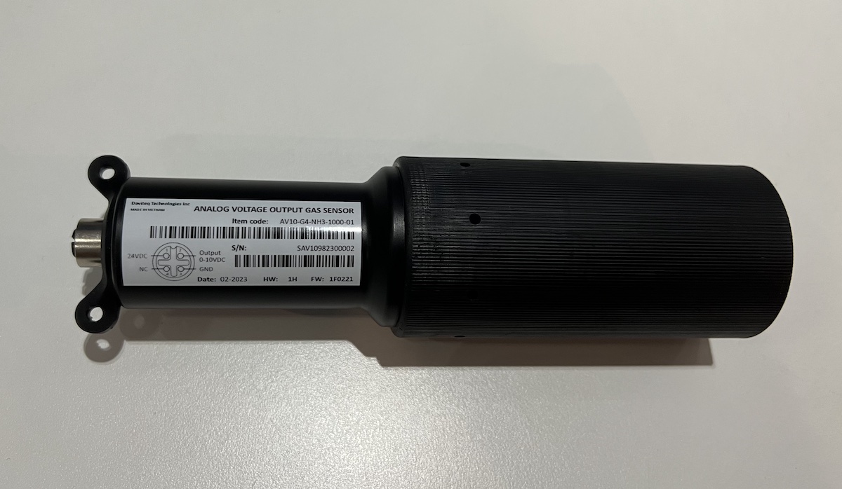
- Manual for AV10-G4-NH3 sensor for Livestock
- Hướng dẫn sử dụng cảm biến AV10-G4-NH3 dùng cho chăn nuôi
Daviteq G4 Gas Sensor - Measurement Principle
1. Introduction
1.1 Overview
Daviteq G4 Gas sensor module is a gas measuring module that utilizes the Seri-4 electrochemical sensor with a high sensitivity to low concentrations of detected gas, high selectivity, and a stable baseline. It has an ultra-low noise amplifier to amplify the nano-ampere current signal from the sensor and delivers the stable and high-resolution output to the reading devices such as Sub-GHz transmitter, Sigfox transmitter, LoRaWAN transmitter, RS485 output transmitter, etc.
The module can support various types of gas sensors such as CO, NO, NO2, H2S, NH3, O2, O3, SO2, Cl2, HCHO...
Typical Applications: Gas, toxic gas detecting, air quality monitoring for facility, building, pump station, HVAC...
* For some applications with high humidity ambient all the time, the sensor can come with a heater to control the humidity within the working range of the sensor.
1.2 Specification
| Sensor technology | Seri-4 electrochemical gas sensor. Please check this link for the specifications of each gas type. |
| Sensor housing / Rating | SS316/SS304 housing with 316SS sintered filter / for Indoor use (buy the optional accessory rain-guard for outdoor installation) |
Note: Do not install the sensor where the ambient humidity is higher than 90% RH most of the time! It will cause the sensor to malfunction.
1.3 Cross Sensitivity Data
What is cross-sensitivity?
The electrochemical sensor is normally affected by other gas. It meant the sensor not only measure the target gas but also the other gases. If there is a concentration of other gas, it would also cause the change in sensor output with a factor listed in the below table.
Please check the cross-sensitivity data of each gas type in this link.
2. Detail measurement principle
The very low current from the gas sensor is amplified by a special amplifier circuit to deliver stable and high resolution.
The special mechanism provides noise filtering so that it can deliver a very stable output. The ADC chip can provide a resolution from 16-bit to 24-bit.
The circuit will deliver the digital output to the reading device.
With an ultra-low-power design, it can run by battery for 10-20 years!
The G4 sensor module will deliver 02 values:
- Gas concentration, in ppm or ppb.
- The temperature of the circuit board, in oC.
3. Calibration of the Daviteq G4 Gas Sensor
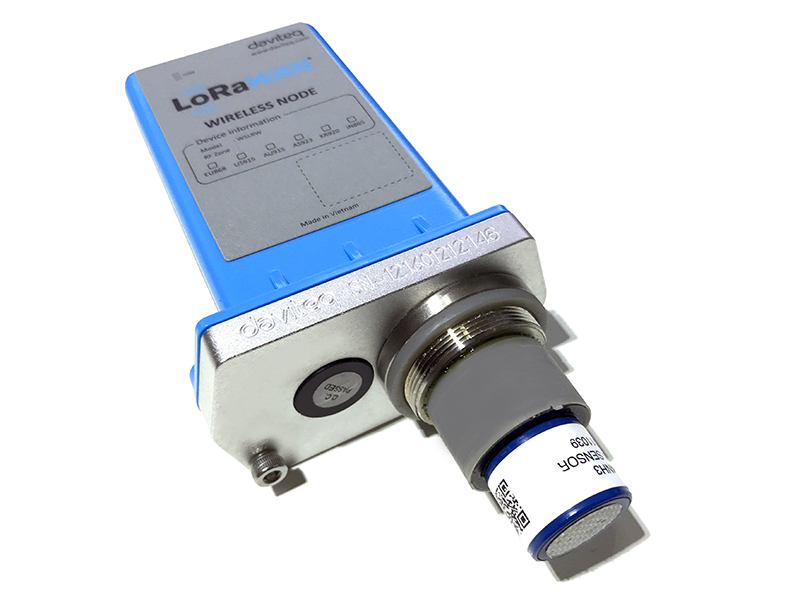
The Daviteq G4 Gas Sensor must be connected to a reading device, normally it is a wireless transmitter like Sub-GHz, Sigfox, or LoRaWAN.
In the reading device, the following parameter is configured in advanced:
Sensor+amplifier sensitivity (mV/ppm): it is the voltage output of the amplifier circuit = Sensor current output (nA/ppm) x R_gain
For example, with an NH3 gas sensor, the default value of the Sensor current output is 110nA/ppm and R_gain = 100 Kohms.
Therefore, the default NH3 Sensor+amplifier sensitivity = 11 mV/ppm
Depending on the sensor type and R_gain value, the sensor sensitivity must be calculated and pre-configured into the reading device.
3.1 Why do we need to calibrate the gas sensor? There are some reasons:
- The sensor current output of a sensor is different from the other sensor. It is not the same value for all sensors after manufacturing.
- The sensor current output of a sensor will be changed over time. For example, the NH3 sensor current output will be reduced by about 5% of the signal per six months in clean air at 25 oC temperature.
- The R_gain of the circuit also has a 0.1% or 0.05% tolerance;
Therefore, users need to calibrate the sensor before use or in a pre-defined interval time (6 or 12 months for example).
3.2 How to calibrate the G4 Gas sensor?
Instructions to attach the calibration cap onto the sensor module to get Zero or Span values.
|
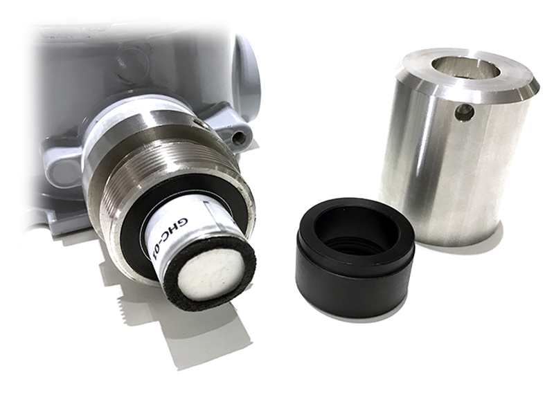
Step 1. Remove the Filter and prepare the calibration cap
|
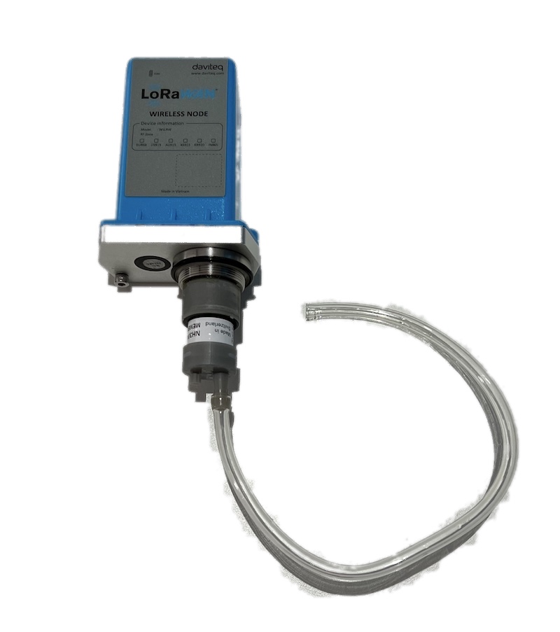
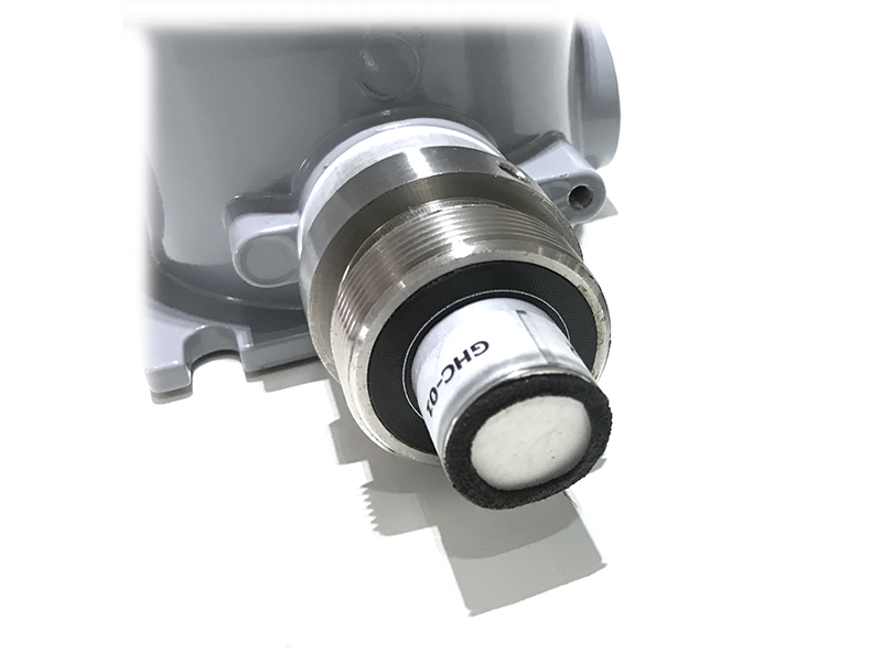
Step 2. Attach the calibration cap to the sensor head
|
|
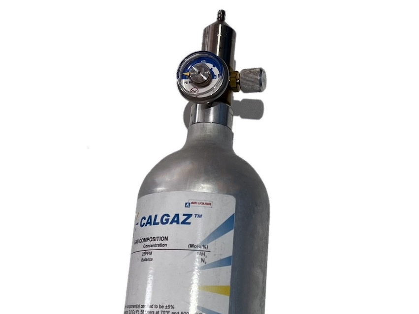
Step 3. Installed the Regulator to the Gas cylinder
|
Step 4. Attach the tube to the regulator
|
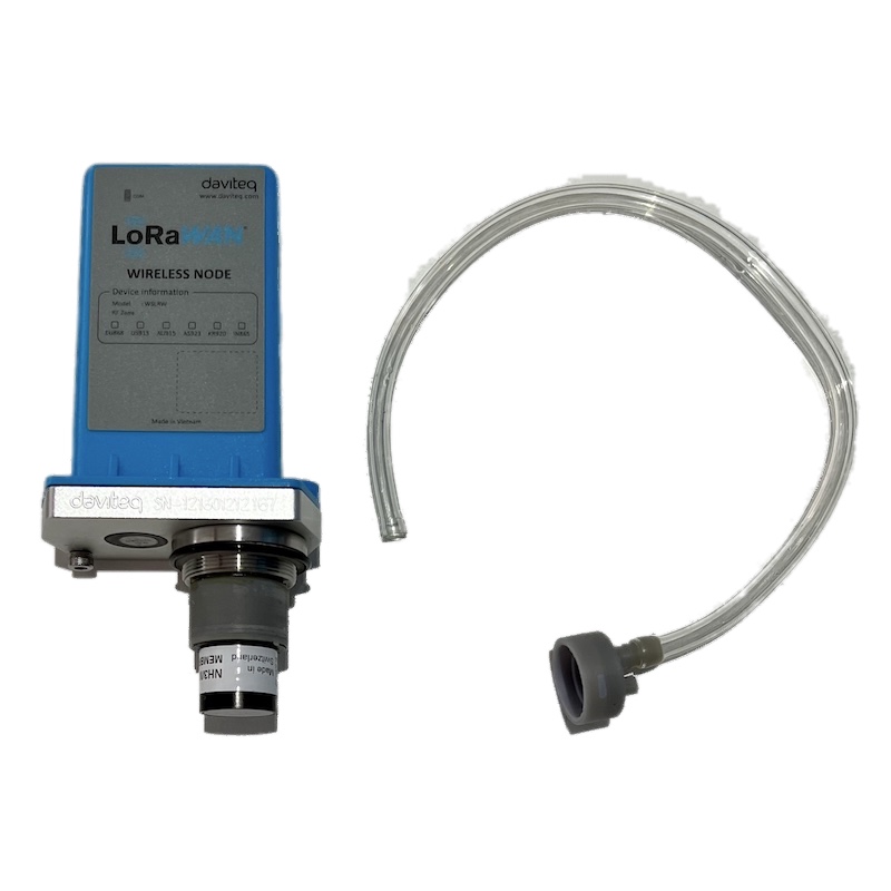
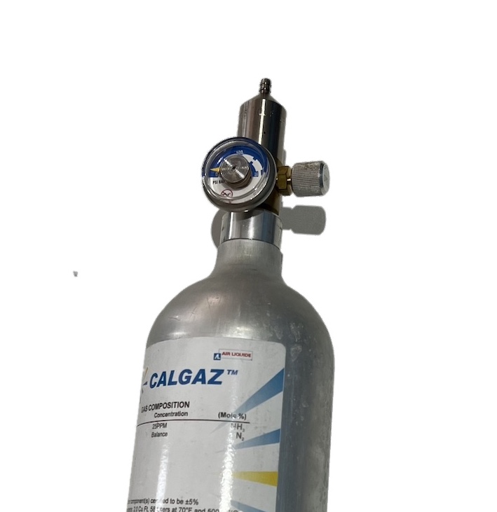
Please use the Flow Regulator with a flow rate of 2.5 LPM or 5.0 LPM.
With the 2-point calibration method, the user can define the A and B factors. Please find below the steps of calibration.
Step 1: Get the Zero value.
- Power ON the device;
- Place the device in a clean-air environment (the target value is nearly zero) at a temperature from 20 - 30 oC, in at least 60 minutes. It is better to use the 99.99% Nitrogen gas as zero gas instead of clean air.
- After 60 minutes, force the device to send data, read and record the Raw_value.
- Recommendation: Record many Raw values at least 10 minutes apart (10 values).
Zero value is the average of the recorded Raw values
Note: the Raw_value can be positive or negative; it will be in the range of -3.00 to +3.00 ppm
Step 2: Get the Span value
Note: Keep the sensor Power ON all the time;
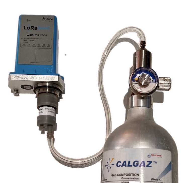
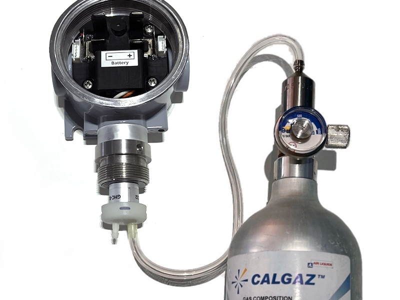
- Use the standard gas cylinder with a known concentration (for example NH3 in N2 with a concentration of 25ppm or 50ppm) to supply the gas to the sensor;
- Use the calibration cap as above pictures to attach to the sensor and connect the tubing to the gas cylinder;
- Open the valve on the Cylinder slowly and make sure the gas has reached the sensor. Please use the Flow regulator 2.5 LPM or 5.0 LPM.
Notes:
- The tube length is short as possible to reduce the gas loss.
- Press a timer to start counting the time;
- After 2 minutes, force the device to send data once every minute, and stop forcing at 5 minutes. The highest Raw_value is the Span value.
Note: Just get one value for Span
- After that, immediately turn OFF the valve to save the gas;
- Remove the calibration cap from the sensor;
- Place the sensor in clean air again.
Note: Always keep the sensor Power ON all the time;
DO NOT PLACE THE SENSOR IN THE SPAN GAS FOR MORE THAN 5 MINUTES; IT WILL SATURATE THE SENSOR OUTPUT AND DEGRADE THE SENSOR LIFE QUICKLY.
Step 3: Calculate the new A and B
-The calculation of new A, B value based on basic linear formula: y = A * x + B
Where:
A, B is calibration coefficients
x is the sensor process value (example gas level in ppm) read on reading device (RAW_VALUE in the payload) such as on application server/network server, on offline tool
y is the correct value. y is the value of standard gas/standard condition
Which condition of Zero value: y0=A * x0 + B
Which condition of Span value: ys=A * xs+ B
From the two formulas, the calculation of A, B as below
A = (y0 - ys) / (x0 - xs)
B = (ys * x0 - y0 * xs)/ (x0 - xs)
-Example of A, B calculation for LoraWAN Ammonia Gas sensor (item code WSLRW-G4-NH3-100-01):
* With condition of clean-air environment at a temperature from 20 - 30 oC, there is no ammonia gas (y0 = 0); while the NH3 level on reading device (RAW_VALUE in the payload) is -0.25 (x0 = -0.25)
* When the sensor is connected to standard gas cylinder having ammonia level of 25 ppm (ys = 25); while the NH3 level on reading device (RAW_VALUE in the payload) is 18.66 (xs = 18.66)
*The calculation of A, B for the Ammonia gas sensor:
A = (0 - 25) / (-0.25 - 18.66) =1.32205
B = (ys * x0 - y0 * xs)/ (x0 - xs) = (25 * (-0.25) - 0 * 18.66)/ (-0.25 - 18.66) = 0.33051
The factory default A = 1 and default B = 0
Use RAW_VALUE in the payload on the reading device for calibration
Step 4: Configure the new A and B into the device
- User can use the off-line tool or downlink to write the values of A and B;
- Writing the new A and B successfully meant you had done the calibration process. Congratulation!
4. Application notes for the Daviteq G4 Gas Sensor
Depending on what type of gas sensor is used in the G4 gas module, the applications will be different. Please refer for some applications:
| Gas type | Typical applications |
| NH3 Ammonia Gas | NH3 leakage detection for HVAC, Chiller... NH3 concentration in the toilet NH3 concentration in the animal farms; chicken, pig, cow... NH3 concentration in the ambient air (Air quality monitor) |
| H2S |
H2S gas monitor for the sewage treatment system H2S gas monitor for basement floor H2S gas monitor for solid waste treatment plant... |
| Cl2 Chlorine gas |
Chlorine gas leakage detection in the chemical process plant Chlorine gas monitoring in ambient air in the water treatment plant Chlorine toxic gas monitoring in the City ... |
5. Installation notes
Notes:
* Avoid the place with humidity higher than 90% RH all the time (a short time in 2-3 days is acceptable)
* if the Sensor is intended to install outdoors, please use a rain guard to protect the sensor from rain and direct sunlight. Please contact us to buy this accessory.
- Place the sensor in the area to monitor the target gas concentration. Please always check the gas molecular weight v.s the air.
- For example, NH3 gas has a lighter weight than air, so the sensor must be placed at a height higher than the source of NH3 leakage. Normally, the sensor will be mounted at a height of 1.6m from the ground.
- For NH3 Odor detection in the toilet, users can place the sensor from 1.6m on the wall or on the ceiling which a height <= 2.6m
Note for Outdoor installation: For outdoor installation, please use the Rain guard to protect the sensor from raindrops or snowflakes. Please find below the steps of installation
|
Step 1. Prepare the rain guard.
|
Step 2. Insert rain guard to the sensor filter and tighten the locking screws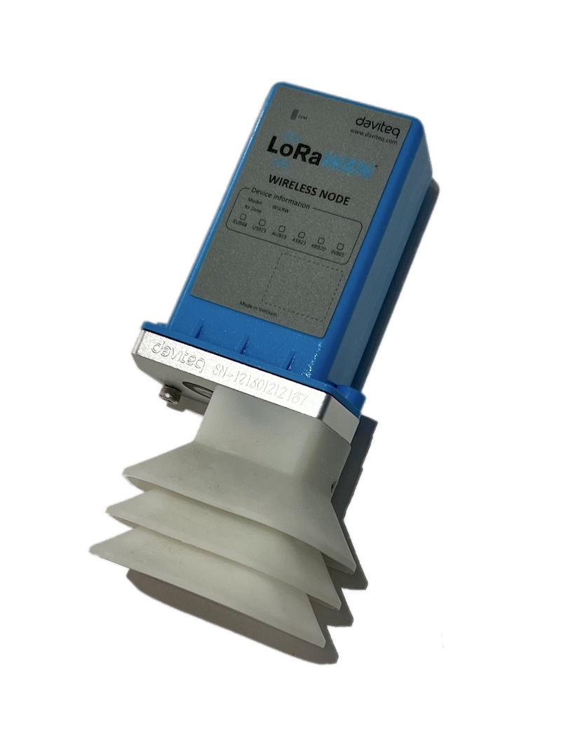 |
6. Troubleshooting for the Daviteq G4 Gas Sensor
| No. | Phenomena | Reason | Solutions | |
| 1 | The measured value is not within the expected value. | 1.1 | The sensor is drifted by time. | Re-calibrate the sensor |
| 1.2 | The sensor was in a high humidity environment (> 90% RH) for more than 03 days continuously. | Place the sensor in low humidity for its recovery. It may take up to 30 days to recover. If the sensor cannot recover after 30 days, please replace the new sensor module. | ||
| 2 | The measured value is always zero or near zero. | 2.1 | The sensor module was removed. | Please check the sensor. |
| 2.2 | The sensor is at the end of its life. | Replace the sensor module | ||
| 3 | HW_Error = 1 | 3.1 | Loosed connection of sensor module and wireless transmitter. | Check the internal wiring. |
| 3.2 | The measuring module got a problem. | Please consult the manufacturer for a warranty or replacement. |
7. Maintenance of the Daviteq G4 Gas Sensor
| What? |
How? |
When? |
| Cleaning the Filter |
Check and clean the filter every few months, depending on the environment. Clean the filter with warm water and soap, then use compressed air to purge it from the inside out. |
Approx. 6-12 months |
| Re-calibration |
The gas sensor may be drifting over time. Please check the sensor specification to identify the interval time for the re-calibration sensor. Please follow the calibration procedure in section 3 above. |
Approx. 6-12 months |
| Sensor replacement |
Replace the new sensor module after 02 years of operation (please check the sensor specification of each gas type). Please see below instructions. |
Approx. 2 years |
Sensor replacement instructions:
* Please remove the batteries before doing the following steps
|
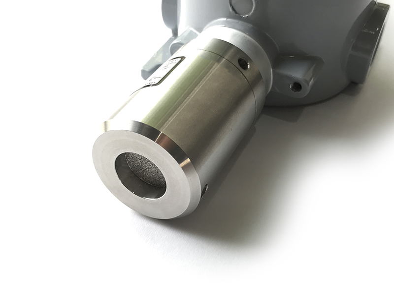
Step 1. Remove the filter
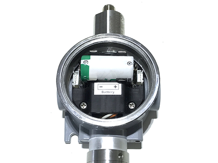
|
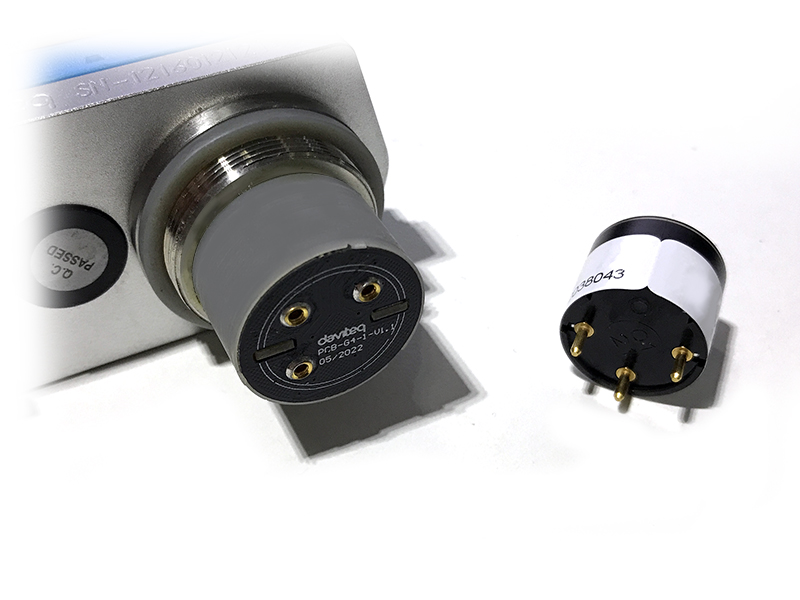
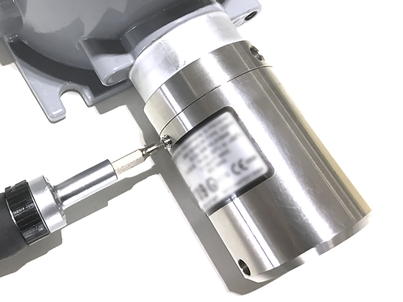
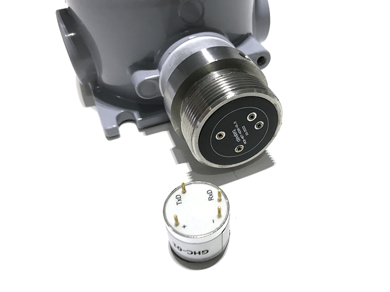
Step 2. Unplug the sensor module
|
|
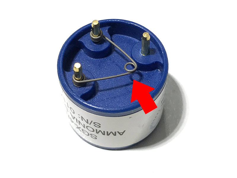
Step 3. Remove the spring clip on the new sensor module.
|
Step 4. Plug the new sensor module into the PCB
|
|
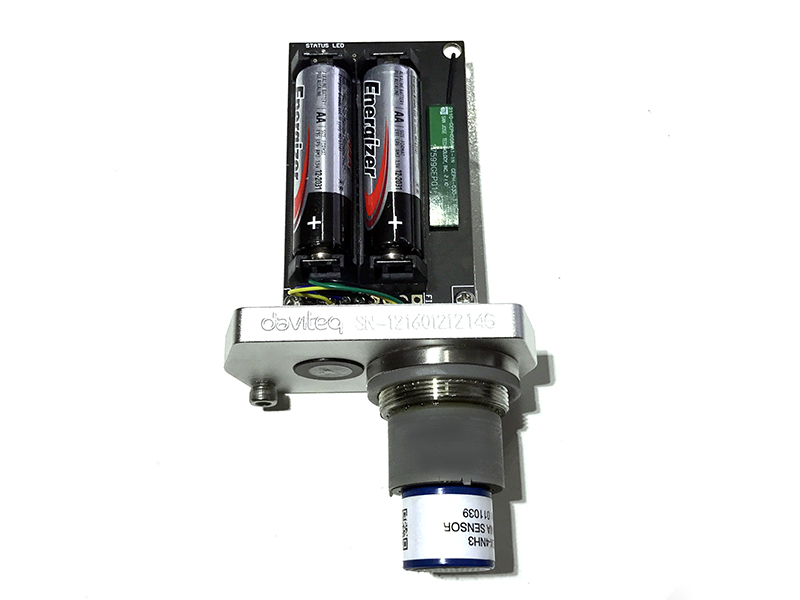
Step 5. Insert the batteries and start calibration of the new sensor as per section 3.
|
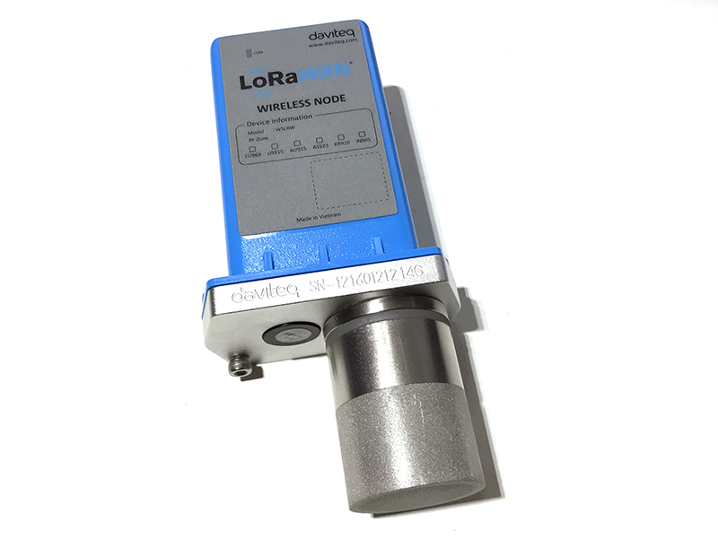
Step 6. Place the filter back.
|
8. Default configuration
This G4 gas sensor module has the default configuration, however, those parameters can be changed. The user can change the configuration on the wireless transmitter so that the complete sensor (transducer + wireless) delivers the proper output value. Below are some configuration parameters that store in the flash memory of the wireless transmitter.
| Description | Unit | Default | Format | Property | Comment |
| CONSTANT_A | 1 | Float | R/W |
Constant a for scaling measured value |
|
| CONSTANT_B | 0 | Float | R/W |
Constant b for scaling measured value |
|
| HIGH_CUT | 1E+09 | Float | R/W |
High cut value for scaled_value |
|
| LOW_CUT | 0 | Float | R/W |
Low cut value for scaled_value |
|
| SENSOR+AMPLIFIER SENSITIVITY | mV | Float | R/W |
Default = 11 for NH3 gas sensor |
END.
Daviteq GHC Flammable Gas Sensor - Measurement Principle
1. Introduction
1.1 Overview
Daviteq GHC Gas sensor module is intended for the automatic continuous measurement of hydrocarbons or carbon dioxide concentration in the atmosphere. The sensor operating principle is based on NDIR technology, i.e. on selective absorption of LED-produced infrared radiation by gas molecules. The differential dual wavelength method allows the elimination of water vapor, optical elements contamination, and other non-selective hindrances influence.
It has ultra-low power consumption to allow it to be integrated with Wireless Devices such as Sub-GHz transmitter, Sigfox transmitter, LoRaWAN transmitter, RS485 output transmitters, etc.
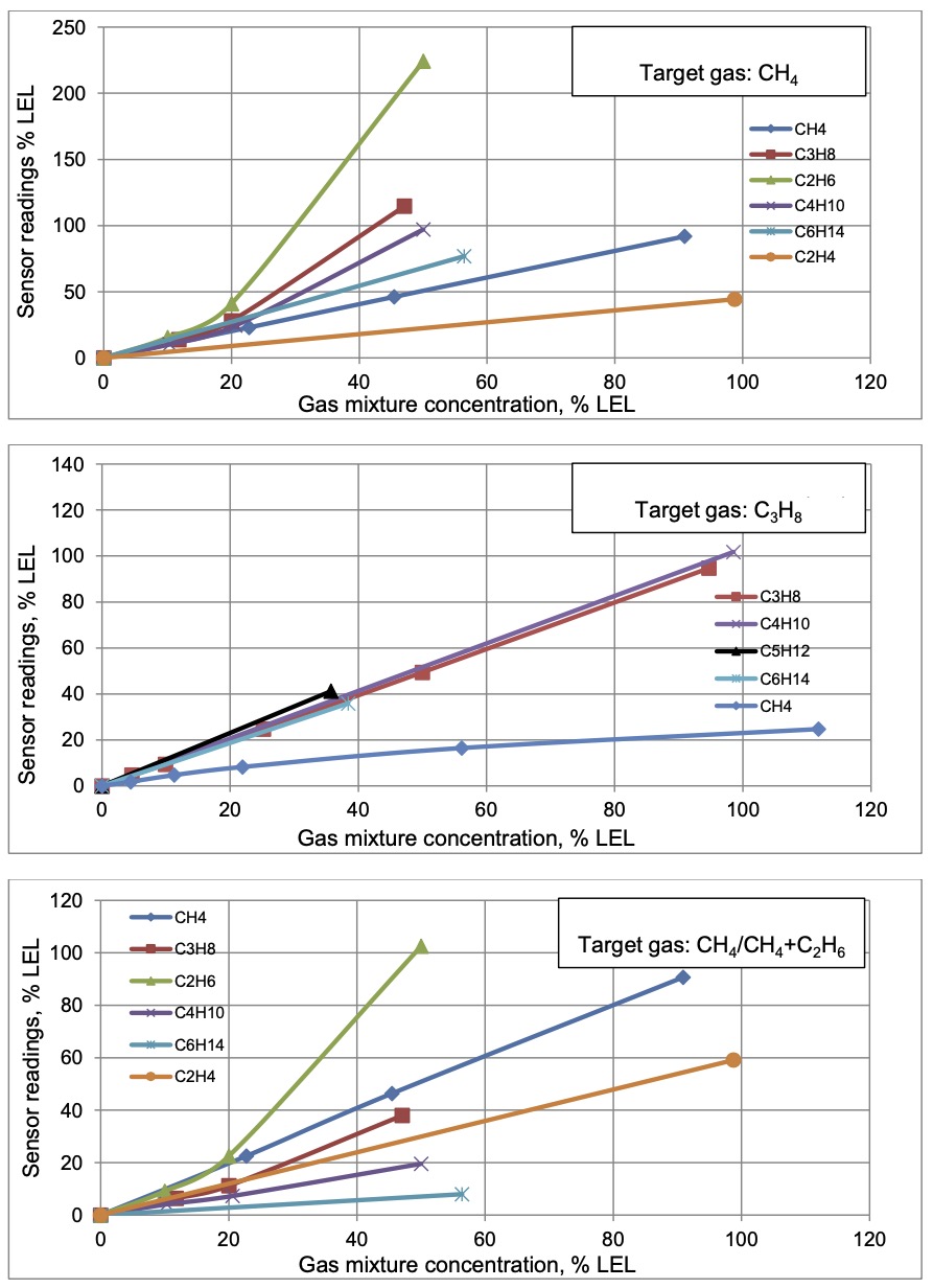
It can be calibrated with target gas like CH4, C3H8, C2H4, and C2H6...
Typical Applications: Flammable gas detection.
1.2 Specification
| Sensor technology | LED-based NDIR |
| Gas sampling method | Diffusion |
| Sensor housing / Rating | SS316/SS304 housing with 316SS sintered filter / for Indoor use (buy the optional accessory rain-guard for outdoor installation), Exd approval for Zone 1 or Zone installation. |
| Target gas | CH4, CH4/CH4+C2H6, C3H8, C2H4,... please consult us for other HC gases |
| Ambient Humidity | 0 - 98% |
| Temperature | -40 .. + 60 oC |
| Atmospheric pressure | 80 .. 120 kPa |
| Warm-up time | 120 sec |
| Measurement range, % vol. | 0 .. 5% vol. CH4, 0 .. 100% vol. CH4, for other ranges please consult us |
| Reading Stability in +20 .. + 25 oC |
± 0.1% vol. or ± 5% of readings (whichever is greater) for CH4 ± 0.05% vol. or ± 5% of readings (whichever is greater) for C3H8 |
| Zero Stability in +20 .. + 25 oC |
for CH4: ± 0.1% vol. or ± 2% LEL |
| Response time T90 | <= 30 sec (with sintered metal filter) |
| Sensor lifetime | >= 10 years |
| Calibration interval | Recommend recalibrating zero and span at least every 30 months |
Detailed reading stability
| Calibration Gas |
Readings stability within a temperature range |
Additional variability due to pressure |
Additional variability due to humidity |
| CH4 |
± 0.1% vol. or ± 5% of readings (whichever is greater) within the range of +20...+25 °C; |
± 0.2% vol. or ± 30% of readings (whichever is greater) at 100 kPa (test: 80 kPa, 100 kPa, 120 kPa) |
± 0.2% vol. or ± 15% of readings (whichever is greater) at 40 °C (test: 20% RH, 50% RH, 90% RH) |
|
± 0.2% vol. or ± 10% of readings (whichever is greater) within the range of |
|||
|
± 0.4% vol. or ± 20% of readings (whichever is greater) within the range of |
|||
| C3H8 |
± 0.05% vol. or ± 5% of readings (whichever is greater) within the range of +20...+25 °C; |
± 0.1% vol. or ± 30% of readings (whichever is greater) at 100 kPa (test: 80 kPa, 100 kPa, 120 kPa) |
± 0.1% vol. or ± 15% of readings (whichever is greater) at 40 °C (test: 20% RH, 50% RH, 90% RH) |
|
± 0.1% vol. or ± 10% of readings (whichever is greater) within the range of |
|||
|
± 0.2% vol. or ± 20% of readings (whichever is greater) within the range of |
1.3 Cross-Sensitivity Data
What is cross-sensitivity?
The gas detection sensor is usually affected by other gas. It meant the sensor not only measure the target gas but also the other gases. If there is a concentration of additional gas, it would also cause a change in sensor output with a factor listed in the below table.
2. Principle of operation
When infrared radiation interacts with gas molecules, infrared light is absorbed by the gas molecules at a particular wavelength, causing vibration of the gas molecules. NDIR (Non-Dispersive Infrared) gas sensors detect a decrease in transmitted infrared light which is in proportion to the gas concentration. This transmittance, the ratio of transmitted radiation energy to incident energy, is dependent on the target gas concentration.
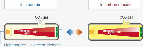
NDIR gas sensor consist of an infrared source, detector, optical filter, gas cell, and electronics for signal processing. A single light source, dual wavelength type gas sensor has two detectors and two optical filters of different wavelengths which are placed in front of each detector. The infrared light that is absorbed by a target gas passes through the active filter with a particular bandwidth for the detection of the target gas. The infrared light that does not interact with the target gas passes through the reference filter. The difference between transmitted light intensities in these two bandwidths is converted into gas concentration. The dual wavelength sensor ensures stable measurements for a long period of operation as the aging effects of the light source or the gas cell are automatically compensated by output signals at the reference wavelength.
Mid-infrared radiation through sample gas causes a resonance of gas molecules at their natural frequency with the infrared light in the spectrum region where the energy level of infrared is equivalent to the natural frequency of gas molecules, resulting in the absorption of infrared by gas molecules in the form of molecular vibration.
The relationship between infrared transmittance and gas concentration is expressed by the Lambert-Beer law:

Where T is transmittance, I is the intensity of light passed through sample gas and an optical filter, Io is the initial light intensity emitted from the source, ε is the molar attenuation coefficient, c is gas concentration, and d is the light path length.
Because ε of the target gas and the light pass length d are fixed with an NDIR sensor, gas concentration can be measured by measuring the transmittance within the spectrum region of the absorbed energy (wavelength) by the target gas.
The initial light intensity emitted from the light source Io is preset by calibration using zero gas which does not absorb infrared light. The initial value of the molar extinction coefficient ε is set by calibration using calibration gas of known concentration.
3. Calibration of the Daviteq GHC Gas Sensor
The Daviteq GHC Gas Sensor must be connected to a reading device, it usually is a wireless transmitter like Sub-GHz, Sigfox, or LoRaWAN.
3.1 Why do we need to calibrate the gas sensor? There are some reasons:
- The output value of a sensor is different from the other sensor. It is not the same value for all sensors after manufacturing.
- The output value of a sensor will be changed over time.
Therefore, users need to calibrate the sensor before use or in a pre-defined interval time (30 months for example).
3.2 How to calibrate the GHC Flammable Gas sensor?
NOTE: THE CALIBRATION CAN ONLY BE DONE IN THE SAFE ZONE!!!
Instructions to attach the calibration cap onto the sensor module to get Zero or Span values.
|
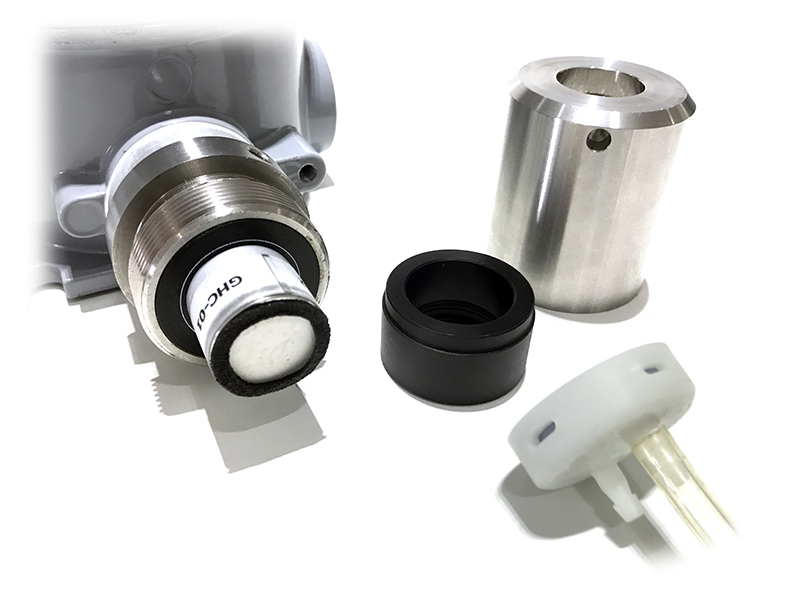
Step 1. Remove the Filter and prepare the calibration cap
|
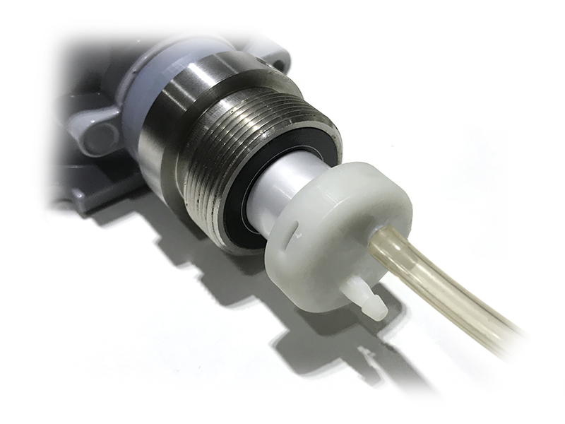
Step 2. Attach the calibration cap to the sensor head
|
|
Step 3. Installed the Regulator to the Gas cylinder
|
Step 4. Attach the tube to the regulator
|
Please select the flow regulator with a flow rate of 2.5 LPM or 5.0 LPM.
With the 2-point calibration method, the user can define the A and B factors. Please find below the steps of calibration.
Step 1: Get the Zero value.
- Power ON the device;
- Place the device in a clean-air environment (the target value is nearly zero) at a temperature from 20 - 30 oC, in at least 60 minutes.
- After 60 minutes, force the device to send data, read and record the Raw_value, so now you got the Zero_value = Raw_GHC value.
Recommendation: Record many Raw_GHC values at least 10 minutes apart (10 values).
Zero value is the average of the recorded Raw values.
Note: the Raw_GHC values can be positive or negative; Its value is usually 7 (%LEL)
Step 2: Get the Span value
Note: Keep the sensor Power ON all the time;
- Use the standard gas cylinder with a known concentration (for example Eythylene Air 1.35% is equivalent to 50 %LEL ) to supply the gas to the sensor;
- Use the calibration cap as above pictures to attach to the sensor and connect the tubing to the gas cylinder;
- Open the valve on the Cylinder slowly and make sure the gas has reached the sensor. The flow regulator should be 2.5LPM or 5.0LPM.
Notes:
- The tube length is short as possible to reduce the gas loss;
- Press a timer to start counting the time;
- After 2 minutes, force the device to send data once every minute, and stop forcing at 5 minutes;
- The highest Raw_value is the Span value.
Note: just get one value for Span
- After that, immediately turn OFF the valve to save the gas;
- Remove the calibration cap from the sensor;
- Place the sensor in clean air again.
Note: Always keep the sensor Power ON all the time;
Step 3: Calculate the new A and B
-The calculation of new A, B value based on basic linear formula: y = A * x + B
Where:
A, B is calibration coefficients
x is the sensor process value (example gas level in ppm) read on reading device such as on application server/network server, on offline tool. The process value is the RAW_VALUE in the payload
y is the correct value. y is the value of standard gas/standard condition
Which condition of Zero value: y0=A * x0 + B
Which condition of Span value: ys=A * xs+ B
From the two formulas, the calculation of A, B as below
A = (y0 - ys) / (x0 - xs)
B = (ys * x0 - y0 * xs)/ (x0 - xs)
-Example of A, B calculation for LoraWAN Ammonia Gas sensor (item code WSLRW-G4-NH3-100-01):
* With condition of clean-air environment at a temperature from 20 - 30 oC, there is no ammonia gas (y0 = 0); while the NH3 level on reading device (RAW_VALUE in the payload) is -0.25 (x0 = -0.25)
* When the sensor is connected to standard gas cylinder having ammonia level of 25 ppm (ys = 25); while the NH3 level on reading device (RAW_VALUE in the payload) is 18.66 (xs = 18.66)
*The calculation of A, B for the Ammonia gas sensor:
A = (0 - 25) / (-0.25 - 18.66) =1.32205
B = (ys * x0 - y0 * xs)/ (x0 - xs) = (25 * (-0.25) - 0 * 18.66)/ (-0.25 - 18.66) = 0.33051
The factory default A = 1 and default B = 0
The RAW_VALUE in the payload is used for calibration
Step 4: Configure the new A and B into the device
- User can use the off-line tool or downlink to write the values of A and B;
- Writing the new A and B successfully meant you had done the calibration process. Congratulation!
4. Application notes for the Daviteq GHC flammable Gas Sensor
-
Do not use a damaged sensor. It must be repaired only by personnel authorized by the manufacturer.
-
Keep the sensor out of contact with aggressive substances e.g. acidic environments, which can react with metals, as well as solvents, which may affect polymeric materials.
-
Diffusion holes of the sensor should be protected against the ingress of sprayed liquid or waterdrops.
-
The sensor is not intended to measure the target gas concentration contained in fluids.
-
Correct measurement is provided when the ambient temperature changes not faster than 0.6 °C/min.
- Inspection and maintenance should be carried out by suitably trained personnel.
-
Persons, who have studied this UM, must be briefed on safety precautions when operating electrical equipment intended for use in explosive areas in due course.
-
When dealing with a cylinder containing a gas mixture under pressure, it is necessary to follow safety regulations.
-
There is no risk of pollution or negative impact on human health. The sensor does not contain any harmful substances that may be released during its normal operation.
5. Installation notes
Notes:
* If a sensor has been kept in transport containers at temperatures below zero centigrade, leave it at +10...+35 °C for not less than one hour.
* if the Sensor is intended to install outdoors, please use a rain guard to protect the sensor from rain and direct sunlight. Please contact us to buy this accessory.
- Place the sensor in the area to monitor the target gas concentration. Please always check the gas molecular weight v.s the air.
Note for Outdoor installation: For outdoor installation, please use the Rain guard to protect the sensor from raindrops or snowflakes. Please contact us to buy the Rainguard.
6. Troubleshooting for the Daviteq GHC Flammable Gas Sensor
| No. | Phenomena | Reason | Solutions | |
| 1 | The measured value is not within the expected value. | 1.1 | The sensor is drifted by time. | Re-calibrate the sensor |
| 1.2 | The sensor was spoiled. | Please consult the manufacturer for a warranty or replacement. | ||
| 2 | The measured value is always zero or near zero. | 2.1 | The sensor module was removed. | Please check the sensor. |
| 2.2 | The sensor is at the end of its life. | Replace the sensor module | ||
| 3 | HW_Error = 1 | 3.1 | Loosed connection of sensor module and wireless transmitter. | Check the internal wiring. |
| 3.2 | The measuring module got a problem. | Please consult the manufacturer for a warranty or replacement. |
7. Maintenance of the Daviteq GHC Flammable Gas Sensor
| What? |
How? |
When? |
| Cleaning the Filter |
Check and clean the filter every few months, depending on the environment. Clean the filter with warm water and soap, then use compressed air to purge it from the inside out. |
Approx. 6-12 months |
| Re-calibration |
The gas sensor may be drifting over time. Please check the sensor specification to identify the interval time for the re-calibration sensor. Please follow the calibration procedure in section 3 above. |
Approx. 30 months |
| Sensor replacement |
Replace the new sensor module only when the sensor cannot respond with standard calibration gas. |
> 10 years or when problem occurs. |
Sensor replacement instructions:
* Please remove the batteries before doing the following steps
|
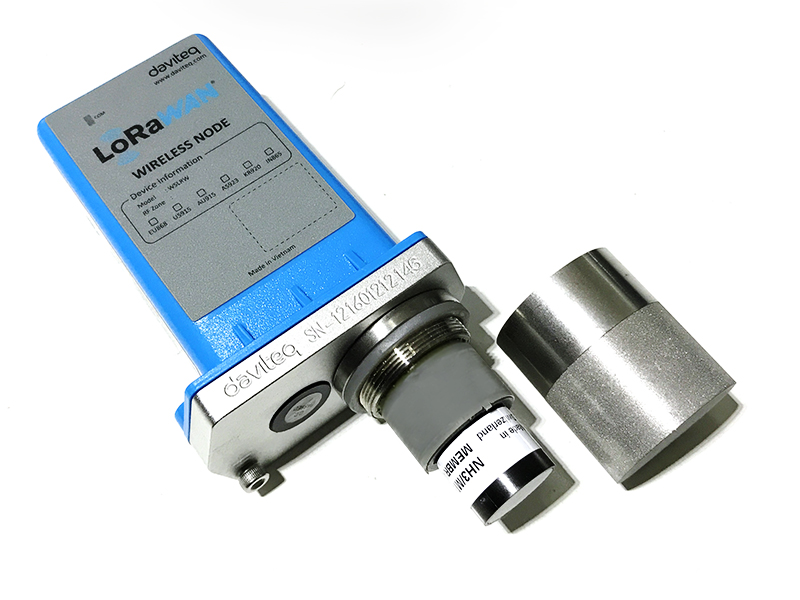
Step 1. Unscrew the housing
|
Step 2. Remove the filter
|
|
Step 3. Unplug the sensor module
|
Step 4. Plug the new sensor module into the PCB
|
|
Step 5. Insert the batteries and start calibration of the new sensor as per section 3.
|
Step 6. Place the filter back.
|
8. Default configuration
This GHC gas sensor module has the default configuration, however, those parameters can be changed. The user can change the configuration on the wireless transmitter so that the complete sensor (transducer + wireless) delivers the proper output value. Below are some configuration parameters that store in the flash memory of the wireless transmitter.
| Description | Unit | Default | Format | Property | Comment |
| CONSTANT_A | 1 | Float | R/W |
Constant a for scaling measured value. This value would be changed after calibration. |
|
| CONSTANT_B | 0 | Float | R/W |
Constant b for scaling measured value. This value would be changed after calibration. |
|
| HIGH_CUT | 1E+09 | Float | R/W |
High cut value for scaled_value |
|
| LOW_CUT | 0 | Float | R/W |
Low cut value for scaled_value |
|
| SENSOR RESPONSE TIME | S | 100 | uint16 | R/W |
* Do not change this value |
| C_H_FACTOR | 4.4 | Float | R/W |
4.4 for CH4, 1.7 for C3H8 |
END.
Manual for AV10-G4-NH3 sensor for Livestock
1. Introduction
Daviteq NH3 Gas sensor for Livestock is a NH3 gas measuring sensor that utilizes the Seri-4 electrochemical sensor with a high sensitivity to low concentrations of detected gas, high selectivity, and a stable baseline. It has an ultra-low noise amplifier to amplify the nano-ampere current signal from the sensor and delivers the stable and high-resolution output.
* For some applications with high humidity ambient all the time, the sensor can come with a heater to control the humidity within the working range of the sensor.
2. Calibration of the Daviteq NH3 Gas Sensor
2.1 Why do we need to calibrate the gas sensor? There are some reasons:
- The sensor current output of a sensor is different from the other sensor. It is not the same value for all sensors after manufacturing.
- The sensor current output of a sensor will be changed over time. For example, the NH3 sensor current output will be reduced by about 5% of the signal per six months in clean air at 25 oC temperature.
- The R_gain of the circuit also has a 0.1% or 0.05% tolerance;
Therefore, users need to calibrate the sensor before use or in a pre-defined interval time (6 or 12 months for example).
2.2 How to calibrate the NH3 Gas sensor?
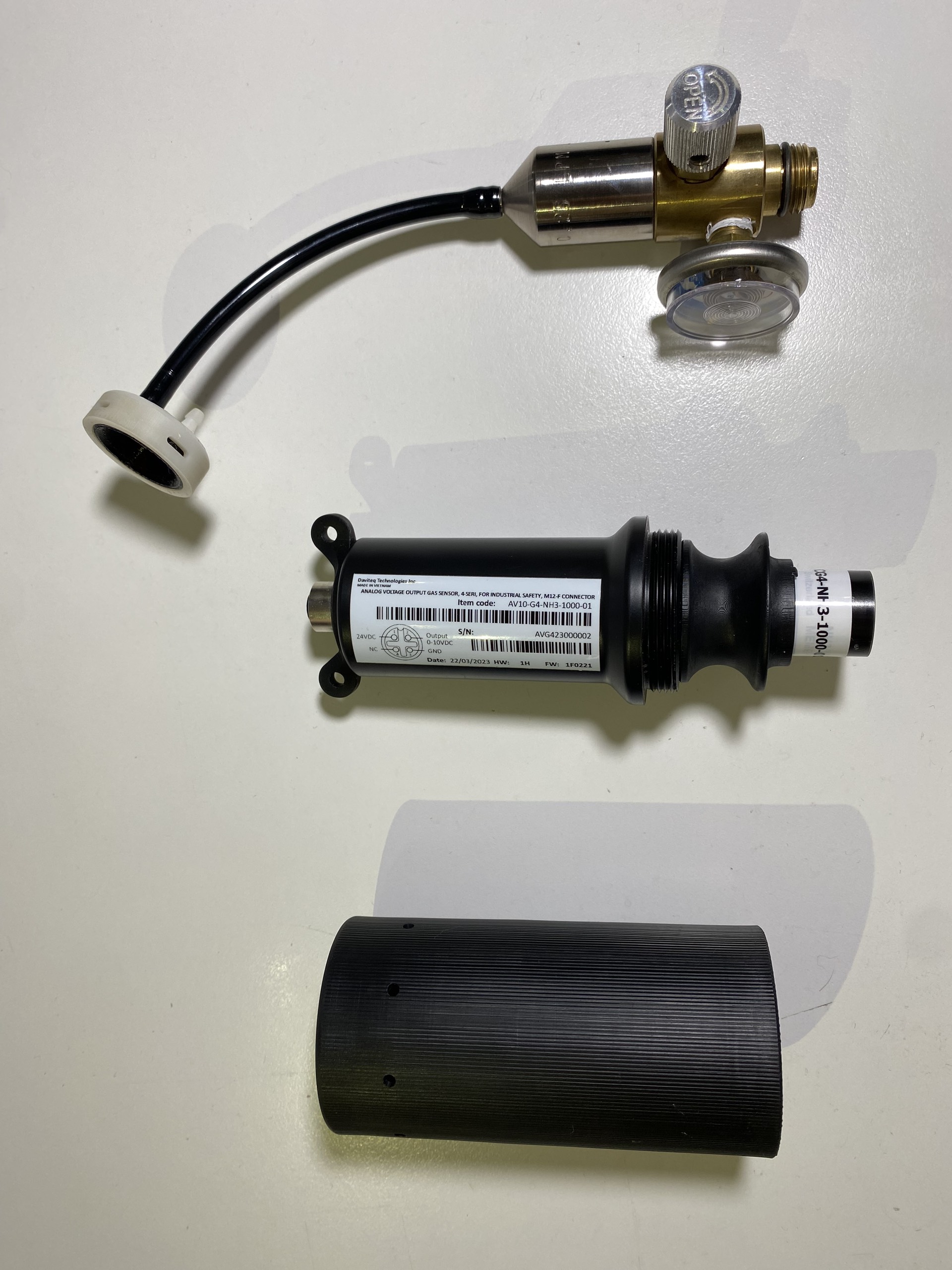
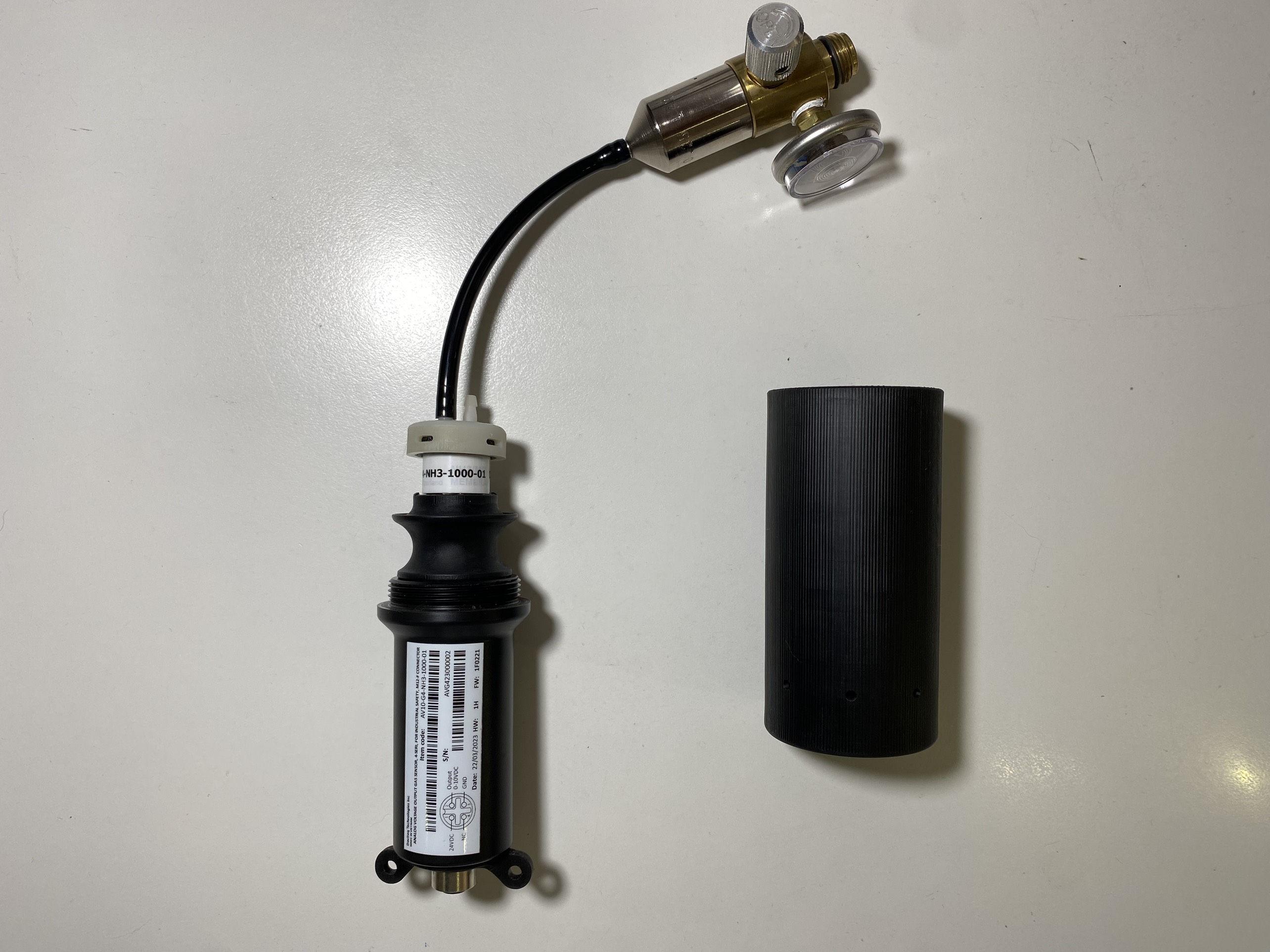
Instructions to attach the calibration cap onto the sensor module to get Zero or Span values.
|
Step 1. Remove the Filter and prepare the calibration cap
|
Step 2. Attach the calibration cap to the sensor head
|
|
Step 3. Installed the Regulator to the Gas cylinder
|
Step 4. Attach the tube to the regulator
|
Please use the Flow Regulator with a flow rate of 2.5 LPM or 5.0 LPM.
Step 1: Get the Zero value.
- Power ON the device;
- Place the device in a clean-air environment (the target value is nearly zero) at a temperature from 20 - 30 oC, in at least 60 minutes. It is better to use the 99.99% Nitrogen gas as zero gas instead of clean air.
- After 60 minutes, record the Voltage output value. Recording multiple values in 5 minutes to calculate the average value.
Step 2: Get the Span value
Note: Keep the sensor Power ON all the time;
- Use the standard gas cylinder with a known concentration (for example NH3 in N2 with a concentration of 25ppm or 50ppm) to supply the gas to the sensor;
- Use the calibration cap as above pictures to attach to the sensor and connect the tubing to the gas cylinder;
- Open the valve on the Cylinder slowly and make sure the gas has reached the sensor. Please use the Flow regulator 2.5 LPM or 5.0 LPM.
Notes:
- The tube length is short as possible to reduce the gas loss.
- Press a timer to start counting the time;
- After 2 minutes, record the voltage output, then record voltage output value again at the minute of 3, 4, and 5. Calculate the average output value of the minutes of 3, 4, and 5.
- After that, immediately turn OFF the valve to save the gas;
- Remove the calibration cap from the sensor;
- Place the sensor in clean air again.
Note: Always keep the sensor Power ON all the time;
DO NOT PLACE THE SENSOR IN THE SPAN GAS FOR MORE THAN 5 MINUTES; IT WILL SATURATE THE SENSOR OUTPUT AND DEGRADE THE SENSOR LIFE QUICKLY.
Step 3: Entering values to reading device
- After Zero and Span, you will get the voltage output correspond to zero gas and span gas value;
- Enter these values into your reading device (PLC...) to get correct reading.
3. Installation
Notes:
* Avoid the place with humidity higher than 90% RH all the time (a short time in 2-3 days is acceptable)
* if the Sensor is intended to install outdoors, please use a rain guard to protect the sensor from rain and direct sunlight. Please contact us to buy this accessory.
3.1 Level of Installation
- Place the sensor in the area to monitor the target gas concentration. Please always check the gas molecular weight v.s the air.
- For example, NH3 gas has a lighter weight than air, so the sensor must be placed at a height higher than the source of NH3 leakage. Normally, the sensor will be mounted at a height of 1.6m from the ground.
3.2 Wiring
Use the M12-Male cable Coding A, 4 pin as below picture.
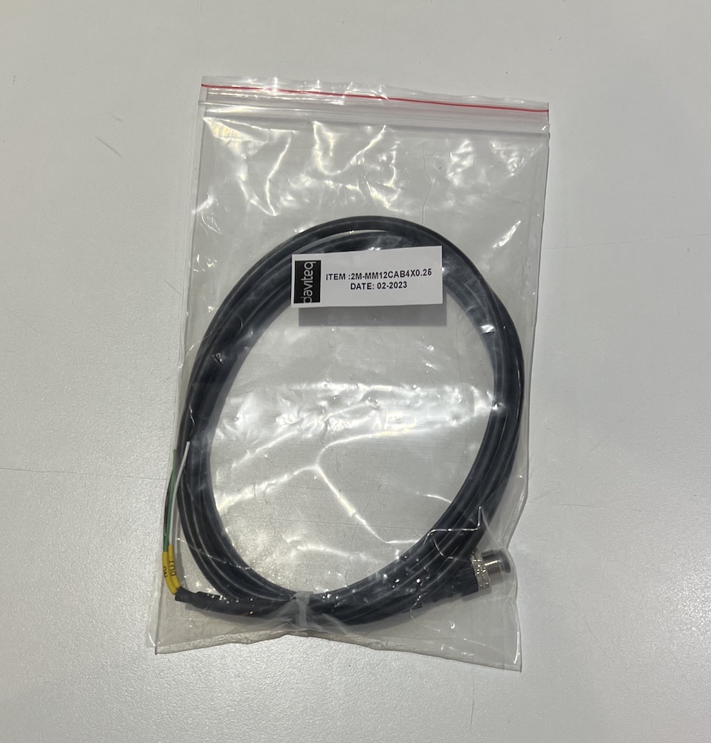
Because the Output is 0-10VDC, we do recommend to use the following cable for extention:
- Cable size: minimum 24AWG (or minimum 0.5 mm2 core)
- Cable type: Shielded
- Max recommended cable legnth: 20m
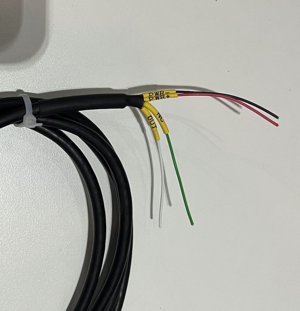
Connect the wires to Reading device as below:
- PWR+: 12-36VDC
- PWR-: GND
- OUT: 0-10VDC OUTPUT
- NC: Not used
Plug the M12 connector to sensor
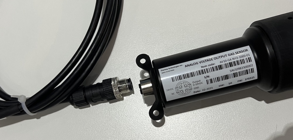
Firmly tighten the M12 connection:
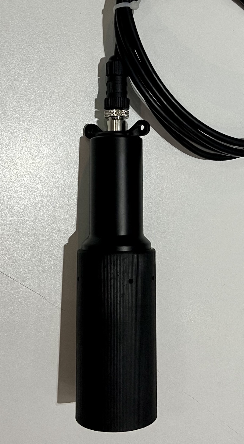
Recommend to use other rope (plastic rope or stainless steel rope) to hang the sensor, it will reduce the tension force of the signal cable.
4. Troubleshooting for the Daviteq NH3 Gas Sensor
| No. | Phenomena | Reason | Solutions | |
| 1 | The measured value is not within the expected value. | 1.1 | The sensor is drifted by time. | Re-calibrate the sensor |
| 1.2 | The sensor was in a high humidity environment (> 90% RH) for more than 03 days continuously. | Place the sensor in low humidity for its recovery. It may take up to 30 days to recover. If the sensor cannot recover after 30 days, please replace the new sensor module. | ||
| 2 | The measured value is always zero or near zero. | 2.1 | The sensor module was removed. | Please check the sensor. |
| 2.2 | The sensor is at the end of its life. | Replace the sensor module | ||
| 3 | The voltage output is 0V or random noise | 3.1 | The wiring problem | Check the wiring and connector M12. Check power supply. |
| 3.2 | The sensor is faulty | Contact manufacturer. |
5. Maintenance of the Daviteq NH3 Gas Sensor
| What? |
How? |
When? |
| Re-calibration |
The gas sensor may be drifting over time. Please check the sensor specification to identify the interval time for the re-calibration sensor. Please follow the calibration procedure as in above section. |
Approx. 6-12 months |
| Sensor replacement |
Replace the new sensor module after 1-2 years of operation (please check the sensor specification of each gas type). Please see below instructions. |
Approx. 1-2 years |
Sensor replacement instructions:
* Please disconnect the device before doing the following steps
|
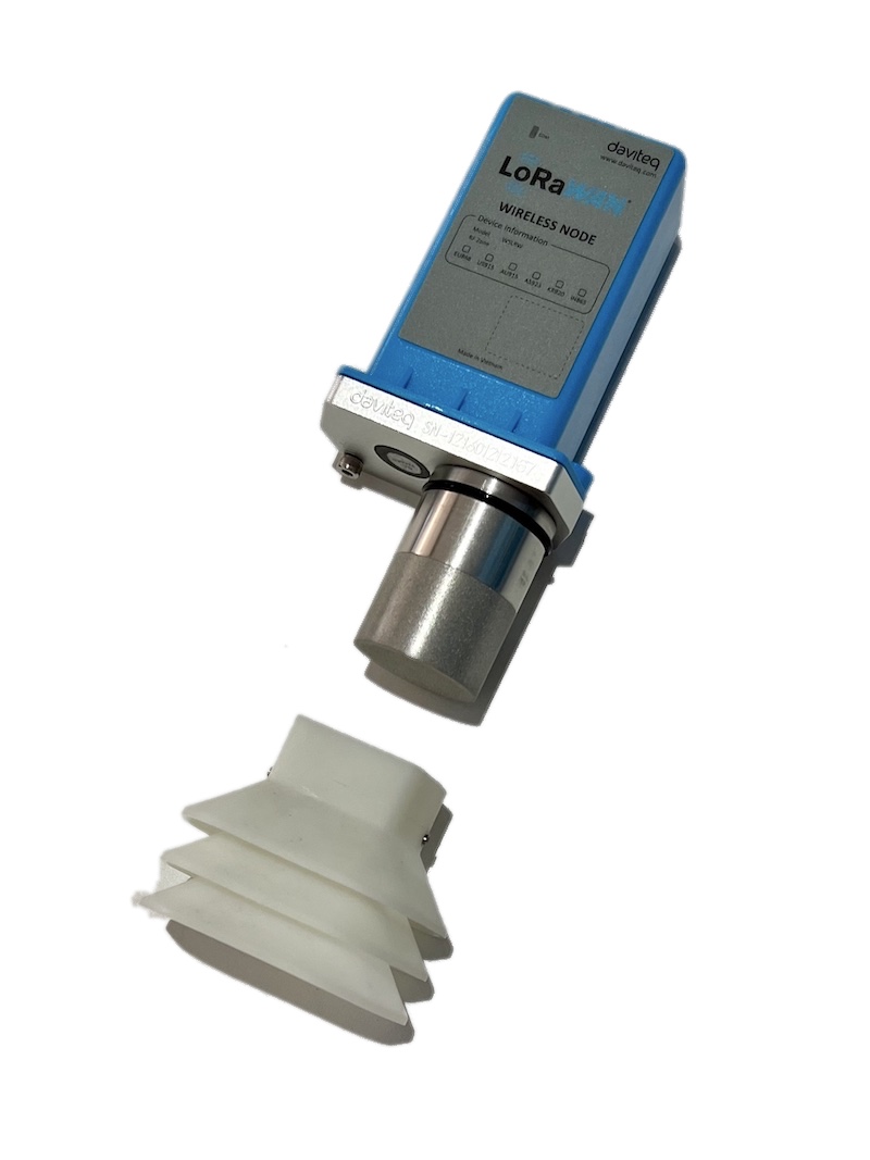
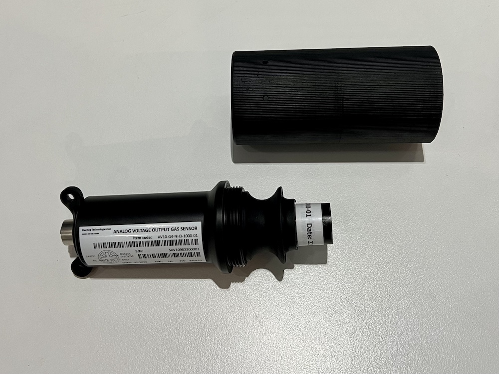
Step 1. Remove the Protector by Rotate it anti-clockwise
|
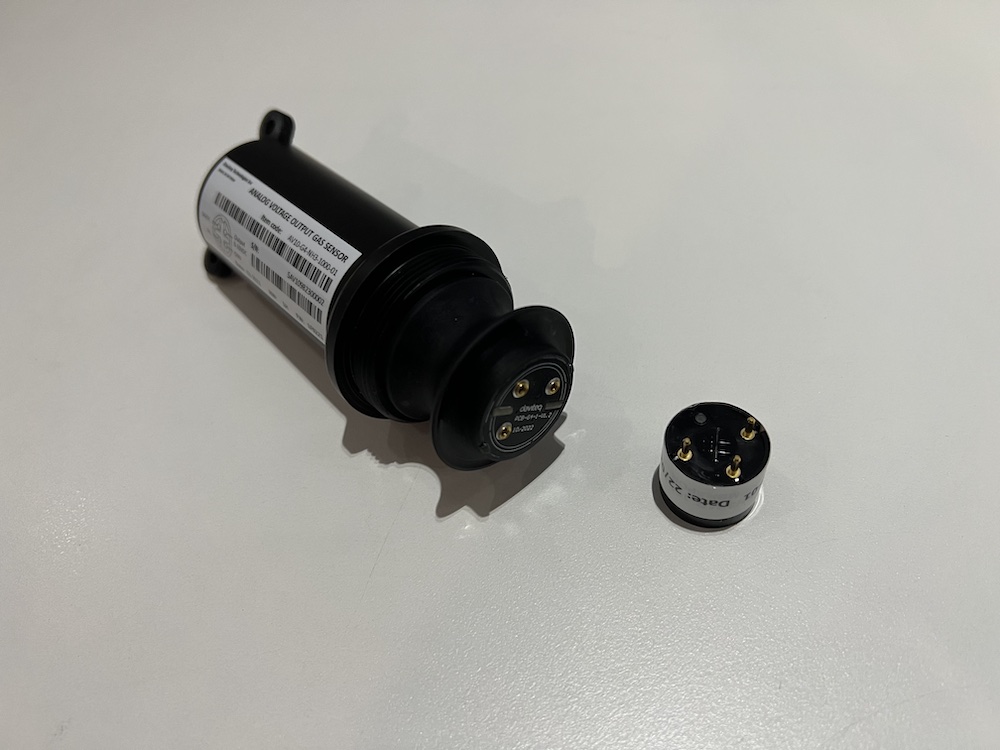
Step 2. Unplug the sensor module
|
|
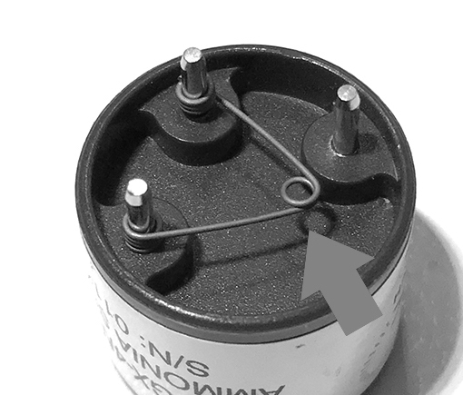
Step 3. Remove the spring clip on the new sensor module.
|
Step 4. Plug the new sensor module into the PCB
|
|
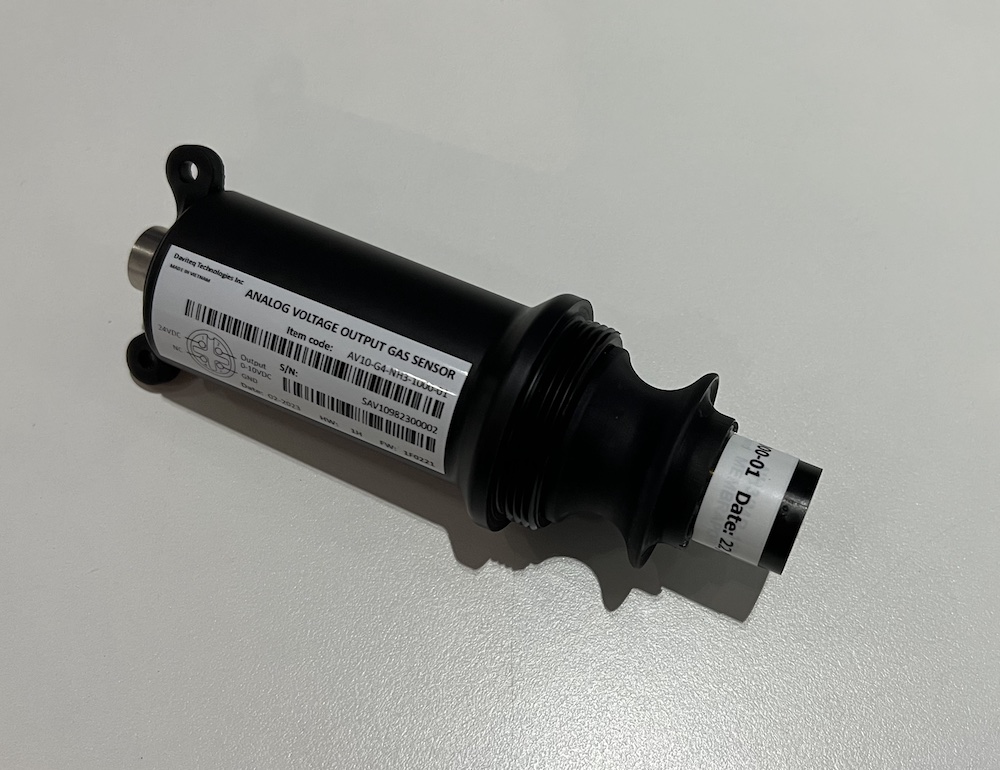
Step 5. Install the Protector back by Rotate it clock-wise
|
|
END.
Hướng dẫn sử dụng cảm biến AV10-G4-NH3 dùng cho chăn nuôi
1. Giới thiệu
Cảm biến khí NH3 của Daviteq dùng cho Chăn nuôi là thiết bị đo nồng độ khí NH3 sử dụng cảm biến điện hóa Seri-4 với độ nhạy cao, có thể phát hiện chính xác khí NH3 với nồng độ thấp, độ chọn lọc cao và ổn định. Thiết bị sử dụng bộ khuếch đại có độ nhiễu cực thấp để khuếch đại tín hiệu dòng điện nano-ampe từ cảm biến cho tín hiệu đầu ra có độ phân giải cao và đáng tin cậy.
*Đối với một số ứng dụng luôn ở trong môi trường độ ẩm cao, cảm biến có thể đi kèm với bộ sưởi để kiểm soát độ ẩm trong phạm vi hoạt động của cảm biến.
2. Hiệu chuẩn cảm biến khí NH3 Daviteq
2.1 Tại sao cần hiệu chuẩn cảm biến khí? Dưới đây là 1 số lí do:
- Tín hiệu dòng điện ra của mỗi cảm biến là khác nhau. Tất cả cảm biến đều có giá trị không đồng nhất sau khi sản xuất.
- Tín hiệu dòng điện ra của cảm biến sẽ thay đổi theo thời gian. Ví dụ, dòng điện đầu ra của cảm biến NH3 sẽ giảm khoảng 5% mỗi sáu tháng trong không khí sạch ở nhiệt độ 25 oC.
- Các linh kiện bo mạch cũng có sai số 0,1% hoặc 0,05%;
Do đó, người dùng cần hiệu chuẩn cảm biến trước khi sử dụng hoặc sau mỗi khoảng thời gian sử dụng (6 hoặc 12 tháng).
2.2 Hướng dẫn hiệu chuẩn cảm biến khí NH3 Daviteq
Hướng dẫn gắn nắp hiệu chuẩn vào mô-đun cảm biến để lấy giá trị Zero hoặc Span.
|
Bước 1. Tháo phần bảo vệ và chuẩn bị dụng cụ hiệu chuẩn
|
Bước 2. Gắn nắp hiệu chuẩn vào mô-đun cảm biến
|
|
Bước 3. Lắp van điều áp vào bình khí chuẩn
|
Bước 4. Kết nối cảm biến vào bình khí chuẩn
|
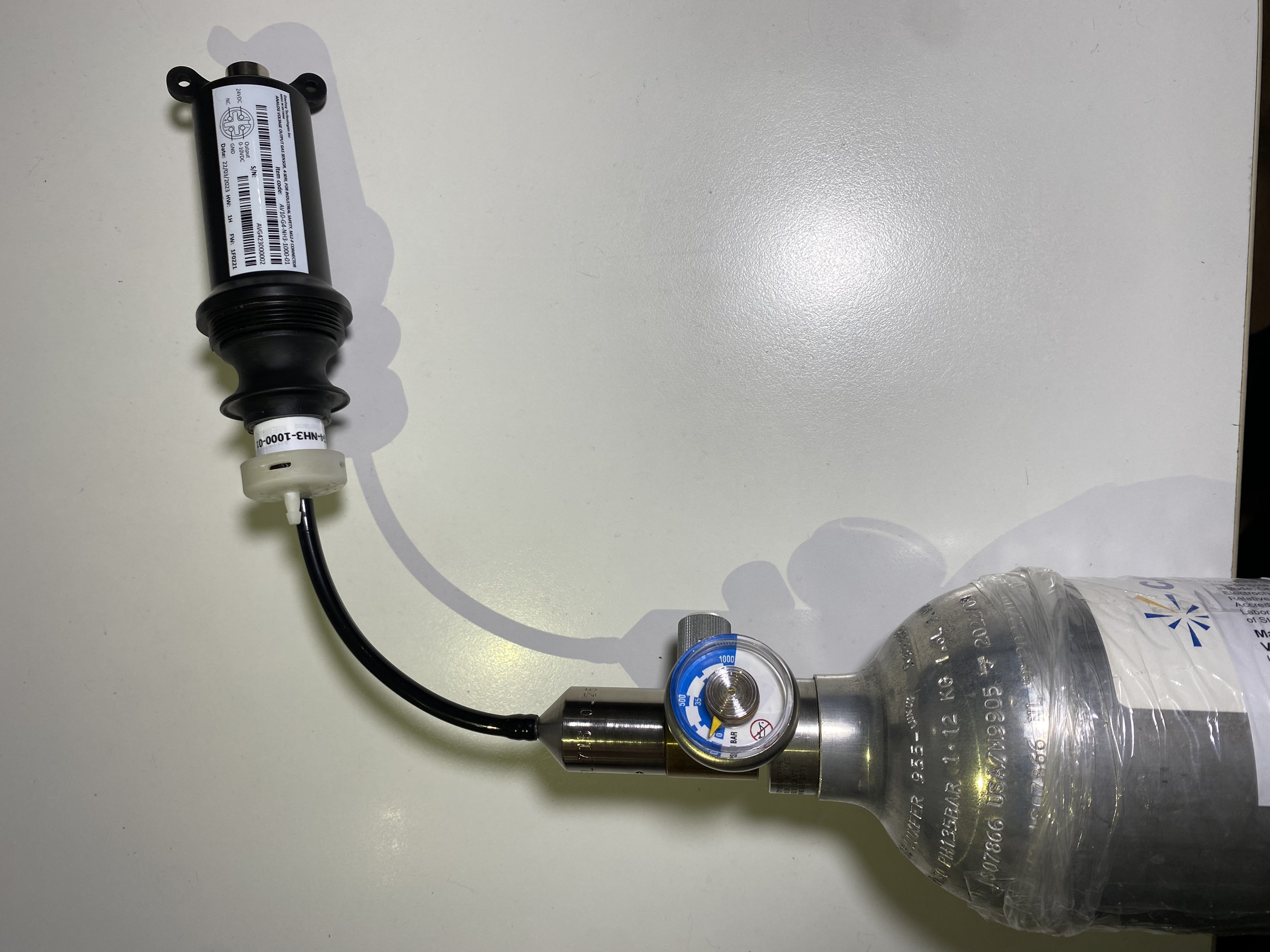
Lưu ý: Sử dụng Bộ điều áp với lưu lượng là 0,25 LPM hoặc 0.5 LPM.
Bước 1: Lấy giá trị Zero.
- Cấp nguồn thiết bị bằng cáp M12 kèm theo.
- Đặt thiết bị trong môi trường không khí sạch (để giá trị gần như bằng 0) ở nhiệt độ từ 20 - 30oC, trong ít nhất 60 phút. Khuyến cáo sử dụng khí Nitơ 99,99% để lấy giá trị Zero chính xác nhất thay vì không khí sạch.
- Ghi nhận giá trị đầu ra sau 60 phút. Lấy nhiều giá trị sau mỗi 5 phút và tính giá trị trung bình.
Bước 2: Lấy giá trị Span
Lưu ý: Không ngắt nguồn thiết bị trong quá trình thực hiện
- Sử dụng bình khí chuẩn với nồng độ định sẵn (ví dụ NH3 trong N2 có nồng độ 25ppm hoặc 50ppm) để cấp khí cho cảm biến;
- Dùng nắp hiệu chuẩn như hình trên để gắn vào cảm biến và nối ống với bình chứa khí;
- Mở van trên bình khí từ từ và đảm bảo khí được lưu thông đến cảm biến. Vui lòng sử dụng van điều áp 0,25 LPM hoặc 0,5 LPM.
Khuyến cáo: Nên sử dụng ống dẫn khí với chiều dài ngắn để giảm thất thoát khí.
- Bắt đầu bấm giờ để đánh dấu mốc thời gian.
- Sau 2 phút, ghi nhận điện áp ra, sau đó ghi lại giá trị điện áp ra ở các phút thứ 3, 4, 5. Tính giá trị trung bình ngõ ra ở các phút 3, 4, 5.
- Sau đó lập tức đóng van điều áp để tiết kiệm khí.
- Tháo nắp hiệu chuẩn khỏi thiết bị
- Đặt thiết bị về lại vùng không khí sạch.
Lưu ý: Không ngắt nguồn thiết bị trong quá trình thực hiện
KHÔNG CẤP KHÍ CHUẨN VÀO CẢM BIẾN QUÁ LÂU (>5PHÚT), SẼ GÂY BÃO HÒA VÀ GIẢM TUỔI THỌ MÔ-ĐUN CẢM BIẾN.
Bước 3: Nhập các giá trị vào thiết bị đọc
- Sau quá trình Zero và Span, ta sẽ có các giá trị điện áp tương ứng với mức khí Zero và Span.
- Nhập các giá trị này vào các thiết bị đọc (PLC,...) để có các kết quả điện áp chính xác.
3. Hướng dẫn lắp đặt
Lưu ý:
* Tránh để thiết bị làm việc liên tục ở môi trường có độ ẩm cao (>90% RH) trong thời gian dài (hơn 3 ngày).
* Nếu thiết bị được lắp đặt ngoài trời, vui lòng sử dụng tấm che mưa để bảo vệ cảm biến khỏi mưa và ánh nắng trực tiếp. Vui lòng liên hệ với NSX để mua phụ kiện này.
3.1 Độ cao lắp đặt
- Đặt thiết bị tại khu vực cần theo dõi nồng độ khí. Hãy luôn kiểm tra trọng lượng phân tử khí cần đo so với không khí.
- Ví dụ khí NH3 có trọng lượng nhẹ hơn không khí nên cảm biến phải đặt ở độ cao cao hơn nguồn phát sinh NH3. Thông thường, cảm biến sẽ được gắn ở độ cao 1,6m so với mặt đất.
3.2 Đấu dây
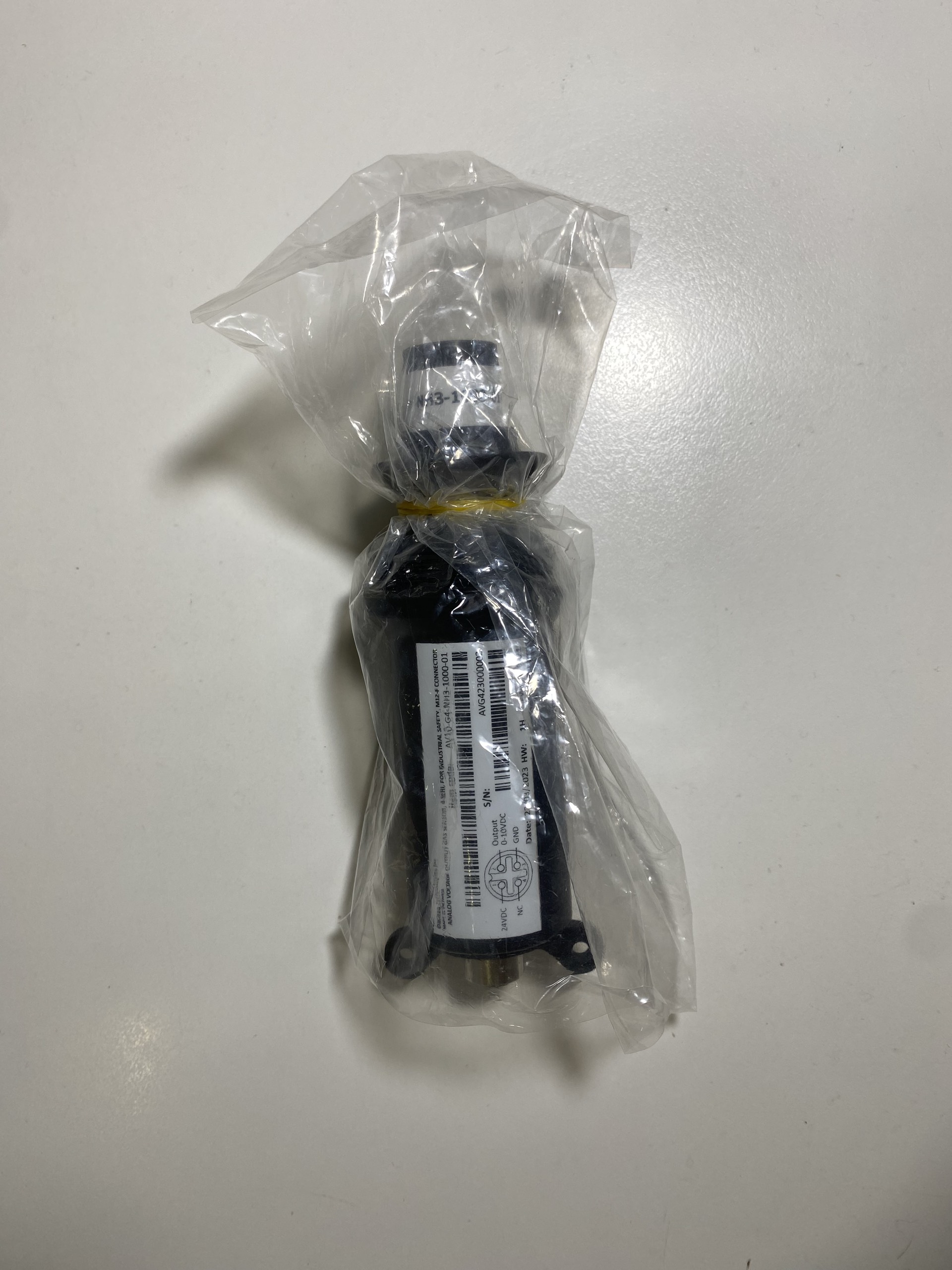
Thiết bị sử dụng cáp M12 đầu Đực Code A 4 lõi như hình dưới:
Vì thiết bị xuất tín hiệu 0-10VDC nên khuyến cáo nên sử dụng dây cáp mở rộng với đặc điểm sau:
- Loại dây có bọc chống nhiễu, tối thiểu 24AWG (hoặc lõi tối thiểu 0,5 mm2)
- Chiều dài dây tối đa: 20m
Kết nối dây với thiết bị đọc như sau:
- PWR+: 12-36VDC
- PWR-: GND
- OUT: 0-10VDC OUTPUT
- NC: Not used
Cắm đầu nối M12 vào cảm biến
Siết chặt kết nối M12:
Nên sử dụng dây khác (dây rút nhựa hoặc dây thép không gỉ) để treo cảm biến, như vậy sẽ làm giảm lực căng của dây cáp tín hiệu.
4. Khắc phục sự cố cho Cảm biến khí NH3 Daviteq
| STT | Hiện tượng | Nguyên nhân | Giải pháp | |
| 1 | Giá trị đo được không nằm trong giá trị mong đợi. | 1.1 | Cảm biến bị trôi theo thời gian. | Hiệu chuẩn lại cảm biến |
| 1.2 | Thiết bị được lắp đặt trong môi trường độ ẩm cao (> 90% RH) liên tục hơn 3 ngày. | Đặt thiết bị ở nơi có độ ẩm thấp để cảm biến phục hồi. Có thể mất tới 30 ngày để hồi phục. Nếu cảm biến không thể phục hồi sau 30 ngày, vui lòng thay mô-đun cảm biến mới. | ||
| 2 | Giá trị đo được luôn bằng hoặc gần bằng 0. | 2.1 | Mô-đun cảm biến mất kết nối với bo mạch | Vui lòng kiểm tra lại kết nối Mô-đun cảm biến với bo mạch. |
| 2.2 | Cảm biến bị hư hỏng | Thay Mô-đun cảm biến. | ||
| 3 | Điện áp ra luôn bằng 0 hoặc bị nhiễu | 3.1 | Lỗi đấu dây |
Kiểm tra lại dây đấu nối và cáp M12. Kiểm tra lại nguồn cấp. |
| 3.2 | Lỗi thiết bị | Vui lòng liên hệ trực tiếp NSX. |
5. Bảo dưỡng Cảm biến khí NH3 Daviteq
| What? |
How? |
When? |
| Hiệu chuẩn lại |
Cảm biến khí có thể bị trôi theo thời gian. Vui lòng kiểm tra các thông số kỹ thuật của cảm biến để xác định khoảng thời gian hiệu chuẩn lại. Quy trình hiệu chuẩn như ở phần trên. |
Sau khoảng 6-12 tháng |
| Thay thế mô-đun cảm biến |
Thay thế mô-đun cảm biến mới sau 1-2 năm hoạt động (vui lòng kiểm tra thông số kỹ thuật cảm biến của từng loại khí). Vui lòng xem hướng dẫn bên dưới. |
Sau khoảng 1-2 năm |
| Vệ sinh chụp bảo vệ cảm biến |
Cần kiểm tra và vệ sinh chụp bảo vệ cảm biến để đảm bảo khí lưu thông dễ dàng vào module cảm biến bên trong, giúp cảm biến đo chính xác. Vui lòng xem hướng dẫn bên dưới. |
Sau khoảng 3-6 tháng |
Quy trình thay thế mô-đun cảm biến:
Vui lòng ngắt kết nối thiết bị trước khi thực hiện.
|
Bước 1. Tháo tấm bảo vệ bằng cách vặn phần vỏ bảo vệ ngược chiều kim đồng hồ
|
Bước 2. Tháo mô-đun cảm biến khỏi bo mạch
|
|
Bước 3. Tháo kẹp lò xo trên mô-đun cảm biến mới
|
Bước 4. Cắm mô-đun cảm biến mới vào bo mạch
|
|
Bước 5. Lắp lại vỏ bảo vệ bằng cách vặn theo chiều kim đồng hồ
|
|
Quy trình vệ sinh thiết bị:
Cần vệ sinh chụp bảo vệ cảm biến định kỳ mỗi 3-6 tháng để đảm bảo cảm biến đo chính xác không khí môi trường xung quanh.
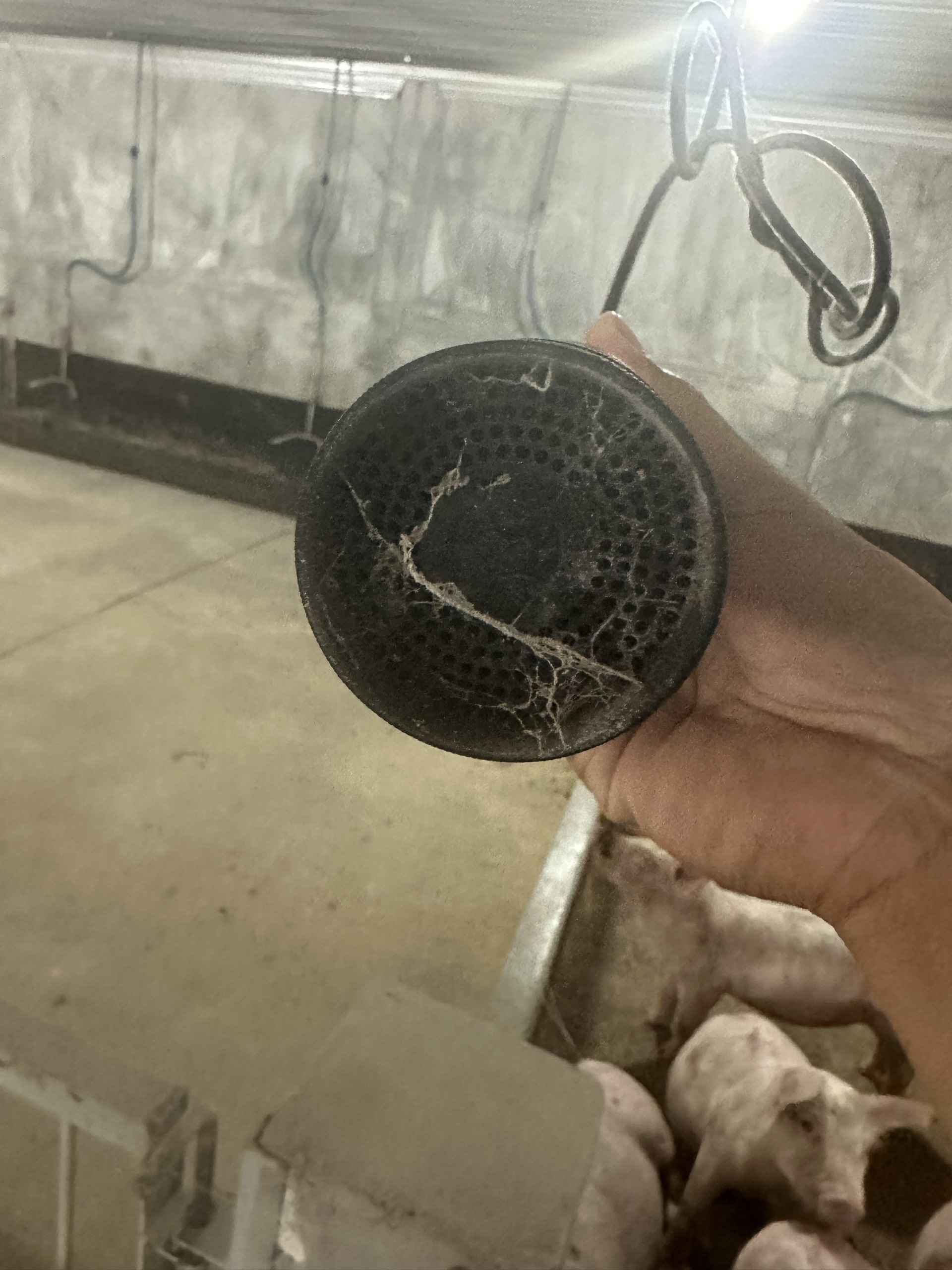
Vui lòng ngắt kết nối thiết bị trước khi thực hiện.
|
Bước 1. Tháo vỏ bảo vệ bằng cách vặn phần vỏ ngược chiều kim đồng hồ
|
Bước 2. Dùng bao nylong và dây thun (dây chun) để bọc lại mô-đun cảm biến, chống nước và hơi ẩm thâm nhập vào đầu cảm biến, tránh rơi rớt và các tác động xung quanh.
|
|
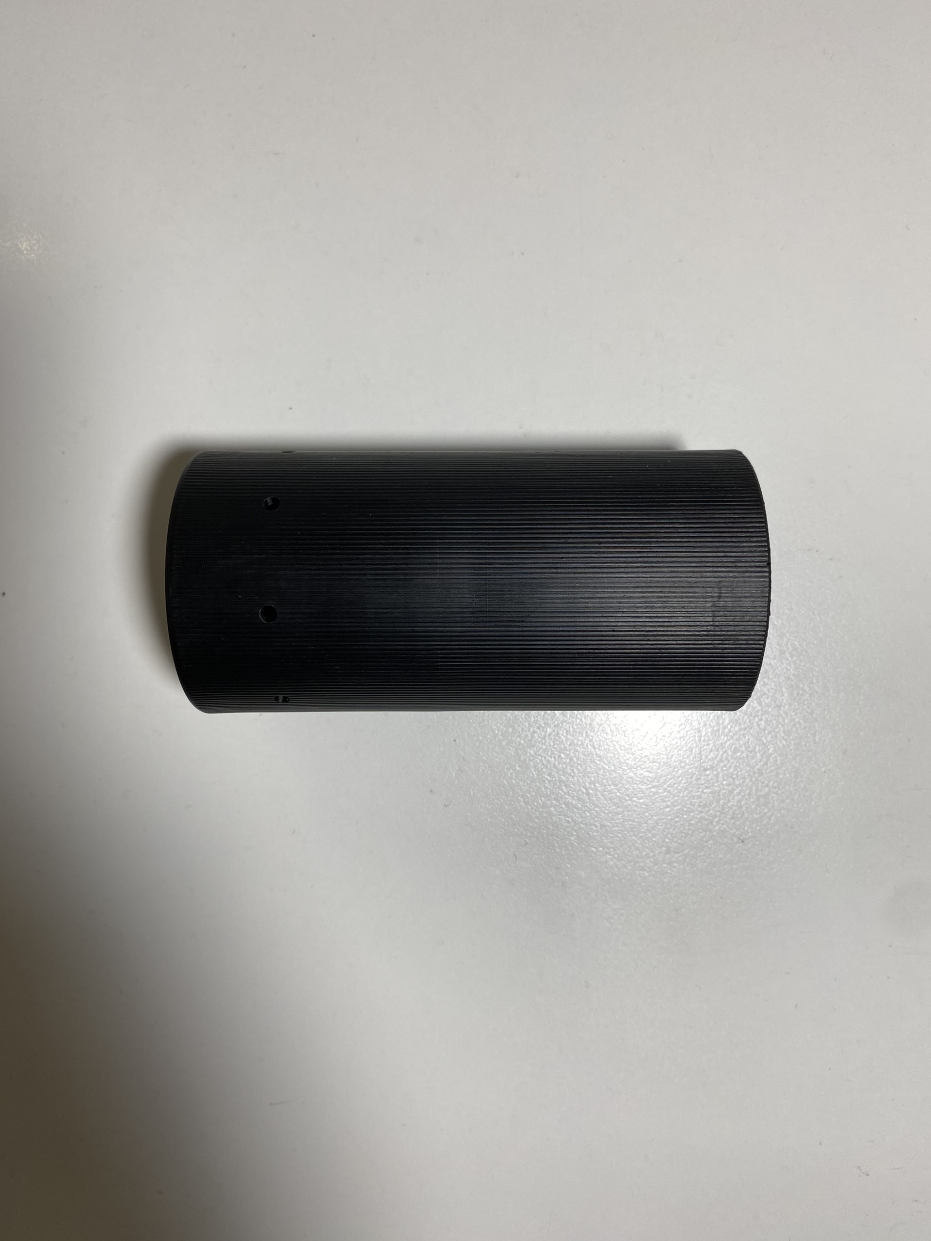
Bước 3. Vệ sinh phần vỏ bảo vệ bằng nước và khí nén. Đảm bảo vỏ bảo vệ khô ráo hoàn toàn sau khi vệ sinh
|
Bước 4. Tháo bao nylon và lắp lại vỏ bảo vệ bằng cách vặn theo chiều kim đồng hồ.
|
END.