Daviteq Inertial Measurement Technologies
Daviteq V1A Vibration Sensor
1. Overview
Daviteq V1A Vibration Sensor is a vibration sensing module that utilizes the Piezo acceleration sensor to measure the vibration with a frequency of up to 10 kHz for condition monitoring and preventive maintenance applications.
The piezo-electric accelerometer is available in ranges ±25g or 50g and features a flat frequency response up to >10kHz. Its accelerometer feature a stable piezo-ceramic crystal in shear mode with low-power electronics, sealed in a fully hermetic package. The Piezo Electric technology V1A accelerometer has a proven track record for offering the reliable and long-term stable output required for condition monitoring applications. The accelerometer is designed and qualified for machine health monitoring and has superior Resolution, Dynamic Range, and Bandwidth to MEMS devices. Besides that, it can also measure the temperature at the mounting point.
With a built-in ultra-low power microprocessor, it can compute and deliver multiple parameters like velocity RMS/Peak, acceleration RMS/peak, displacement RMS/pk-pk, frequency, temperature, crest factor...
The V1A can be integrated into the wireless transmitter from Daviteq such as Sub-GHz WS433, LoRaWAN WSLRW, and Sigfox WSSFC. The connection can be via a 2m cable with an M12 connector or integrated type (WS433 only).
The V1A is also powered by the batteries in the wireless transmitter.
2. Detail measurement principle and its specification
V1A utilizes the single-axis Piezo acceleration sensor to detect the vibration of the object with vibration from 8Hz to 11 kHz.
A built-in high-accuracy solid-state temperature sensor allows the V1A to measure the object's surface temperature.
The microprocessor will capture the raw signal of acceleration and temperature values at a very high speed, up to 290 kHz. With this high-resolution raw signal, it performs various calculations to deliver the high accurate outputs like:
|
Velocity RMS (mm/s) |
Velocity Peak (mm/s) |
|
Acceleration RMS (m/s2) |
Acceleration Peak (m/s2) |
|
Displacement RMS (um) |
Displacement Peak-Peak (um) |
| Frequency of Highest amplitude vibration (Hz) | Surface Temperature (oC) |
These outputs will be sent to the wireless transmitter with a digital signal.
V1A specification
| Sensing technology | Hermetically Sealed, Piezo-Ceramic Crystal, Shear Mode |
|
Acceleration Range & Shock Limit (g) |
±25 or 50, 10,000 |
|
Frequency Response and Resonant (Hz) |
2 .. 10,000, > 30000 |
|
Non-Linearity, Transverse Sensitivity |
±2%FSO, < 5% |
|
Temperature measuring and operating |
-40°C .. +85°C, with accuracy: +/- 0.5 and resolution: 0.125 |
|
Sensor Material, rating, and mounting |
304SUS, IP67, M6 Screw |
|
Connector |
M12-M 5-pin (Coding A) with 2m cable or Integral type |
|
Parameter Measurement |
Acceleration RMS & Peak Velocity RMS & Peak Displacement RMS & Peak Frequency & Temperature |
|
Acceleration range and resolution |
+/- 25G, 6.1 mg |
|
Velocity range and resolution |
0 .. 50 mm/s, 0.1mm/s |
|
Displacement range and resolution |
+/- 5000 um, 1 um |
|
Frequency range and resolution |
2 .. 10,000 Hz, 1 Hz |
3. Calibration of the Daviteq V1A Vibration Sensor
The Daviteq V1A Vibration Sensor is calibrated at the factory. It is recommended the customer to re-calibrate the sensor every 12 months. Please contact us for calibration services.
Notes:
* The calibration and configuration can only be done when the V1A sensor is used with a Wireless transmitter like Sub-GHz (WS433-V1A) or LoRaWAN (WSLRW-V1A) or Sigfox (WSSFC-V1A).
* After that, use the offline tool or downlink to configure the A factor to the device.
4. Application notes for the Daviteq V1A Vibration Sensor
The Daviteq V1A Vibration Sensor together with a wireless transmitter to be used in the following cases:
- Measuring Single-axis vibration and/or surface temperature of Motor, Bearing, Pump, Fan, Gearbox, Rotary machine/equipment, or any object that has a vibration from 8 to 11,000 Hz.
.png)
Figure 1. The V1A sensor is mounted on a motor case.
5. Installation
5.1 Dimension Drawings
|
Figure 2. Dimension drawing of WS433-V1A-... |
Figure 3. Dimension drawing of V1A module which is used for WSLRW or WSSFC |
.png)
.png)
5.2 Mounting Position
Rule of thumb, the V1A will be installed at the place you want to measure the vibration and/or surface temperature.
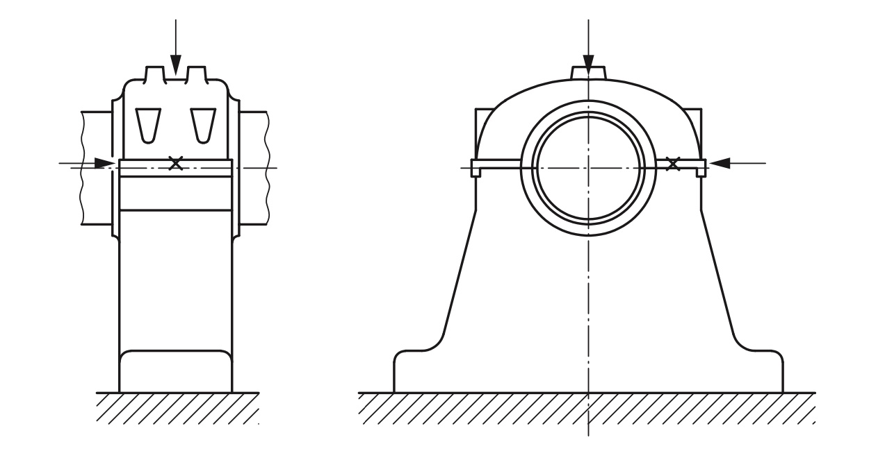
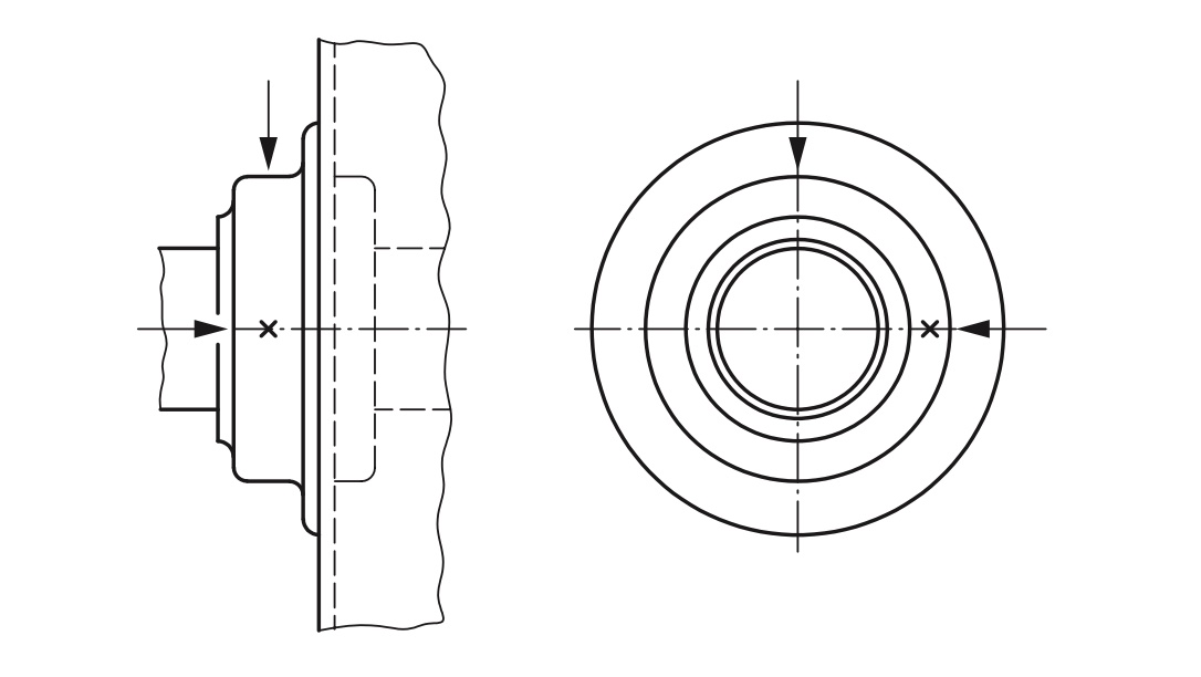
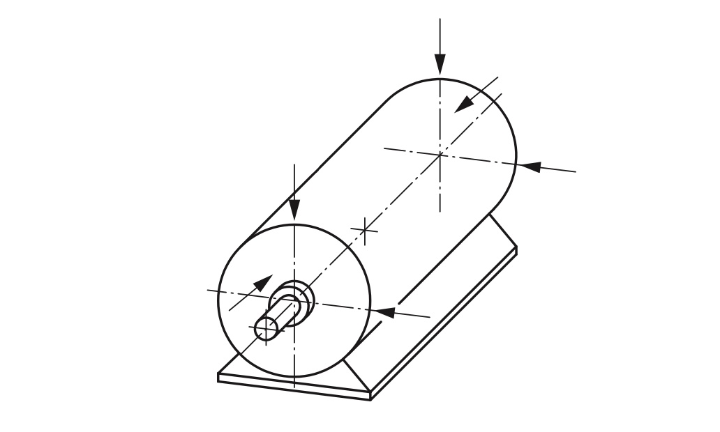
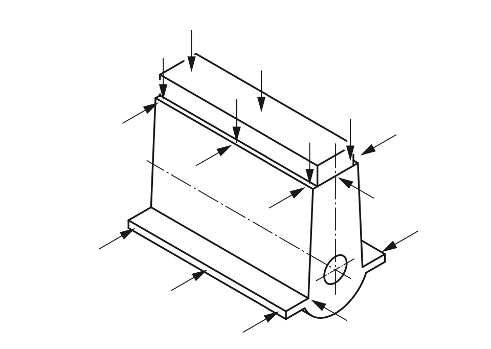
Here are some recommendations for the installation of V1A on some typical equipment based on standard ISO 20816 (or ISO 10816).
|
Figure 4. Measuring points for pedestal bearings |
|
|
Figure 6. Measuring points for small electrical machines |
Figure 7. Measuring points for reciprocating engines close to the bearing locations |
|
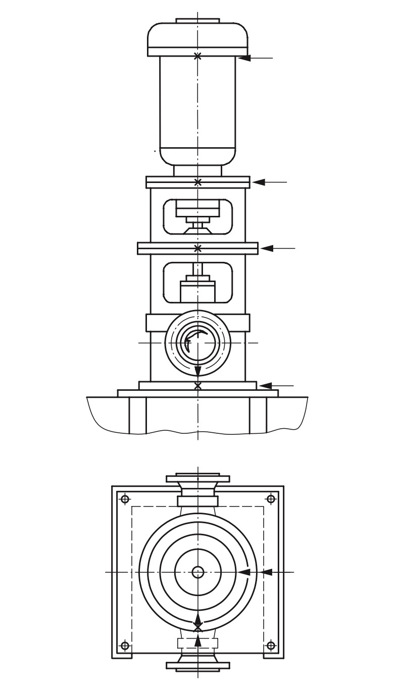
Figure 8. Measuring points for vertical machine sets |
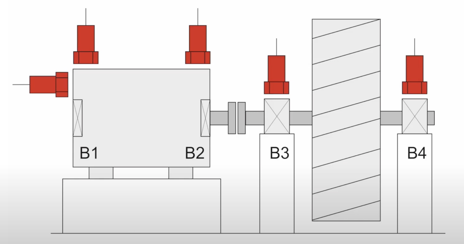
Figure 9. A pump system with 4 bearings and 5 positions of vibration monitoring |
5.2 Mounting the sensor on the equipment's surface
The V1A sensor has the inner threads M6 and there is an M6 screw that comes with the sensor as standard.
There are 02 cases of mounting:
5.2.1 There are male threads or female threads at the place to mount the sensor:
- The V1A can be installed directly on the equipment's surface via an M6 screw or an adapter if the threads on the equipment are not M6. Please see the below figures.
|
Figure 10. There is inner threads M6 on the motor casing |
Figure 11. Mount the sensor on the M6 screw |
.png)
5.2.2 There are no male threads or female threads at the place to mount the sensor:
- If the drilling is allowed, please make a drilled hole and then tap the inner threads M6 on the surface of the equipment so that you can install the V1A directly on the surface of the equipment. Please see the below figure.
.png)
Figure 12. Drilling and tapping an inner threads M6 on motor casing
- if the drilling is NOT allowed, you can use the adhesive base (Item code: ACC-V1A-BASE-01) for mounting the V1A on the equipment. Please contact us for more information about this accessory.
Here are the steps to attach the adhesive base to the equipment's surface.
* Use sandpaper to remove the deposit or paint layer on the surface of the equipment;
* Clean the surface with alcohol;
* Mix 2-part of putty epoxy. Refer the instruction to mix 2-part of putty epoxy on the label of putty epoxy package.
* Apply the 2-part putty epoxy on the bottom surface of the base;
* Place the base on the surface;
* Use the leveling meter to level the surface of the base in 02 directions X and Y;
LEAVE IT COMPLETELY DRY AND HARDEN IN AT LEAST 24 HOURS
* Screw the M6 screw and install the sensor module.
|
Figure 13. Place the base with Epoxy on the equipment's surface |
Figure 14. Leveling it in the X direction |
|
Figure 15. Leveling it in the Y direction |
Figure 16. Leave it dry for 24 hours before installing the sensor |
.png)
.png)
.png)
.png)
Note: the adhesive base is for a flat surface only or a curved surface with a radius larger than 500mm.
5.3 Connect the M12 cable (for LoRaWAN of Sigfox Version)
Figure 13. Connect the M12 cable to the sensor module
6. Troubleshooting for the V1A Sensor
| No. | Phenomena | Reason | Solutions | |
| 1 |
The wireless transmitter is still running and sending data, however, all the measurement parameters are not updated with new values |
1.1 | The connection between the V1A sensor and the wireless transmitter is broken! |
For LoRaWAN or Sigfox version: check the M12 connector and the cable to see any abnormal or looseness.
For the WS433 version: check the looseness of connection between sensor and transmitter. |
| 1.2 | The battery is almost draining off. | Check the battery status and replace it when necessary. | ||
| 2 | The measured values are not as expected | 2.1 | The installation is not correct or not suitable for the sensor design. | Please recheck the installation. |
| 2.2 | The sensor is drifting. | Re-calibrate the sensor. Please contact us. | ||
| 3 | The reading values are very noisy even though there is no vibration. | 3.1 | The sensor V1A got a problem. | Please consult the manufacturer for a warranty or replacement. |
| 4 | From system: HW_Error = 1 | 4.1 | The lost connection between the sensor V1A and the wireless transmitter |
For LoRaWAN or Sigfox version: check the M12 connector and the cable to see any abnormal or looseness.
For the WS433 version: check the looseness of connection between sensor and transmitter. |
| 4.2 | The sensor V1A got a problem. | Please consult the manufacturer for a warranty or replacement. |
7. Maintenance of the V1A Vibration Sensor
- There are no moving parts or consumed parts in the V1A Vibration Sensor. Therefore there is no need to do maintenance.
- However, the sensor may be drifting over time. We do recommend customer to re-calibrate it every 12 months. Please follow the calibration procedure in this link.
8. Default configuration
The V1A Vibration Sensor has the default configuration. The user can change the configuration on the wireless transmitter so that the complete sensor (sensor + wireless) delivers the proper output values. Below are some configuration parameters that store in the flash memory of the wireless transmitter.
| Description | Unit | Default | Format | Property | Comment |
| CONSTANT_A | 1 | Float | R/W |
Constant a for calibrating the velocity RMS and thus calibrating the whole vibration sensor |
|
| ENB_DATAGRAM | 1 | Uint16 | R/W | bit0: enable datagram 0 bit1: enable datagram 1 bit2: enable datagram 2 |
|
|
TEMPERATURE_OFFSET_X10 |
oC | 0 | int16 | R/W |
Offset adjustment for measured temperature value |
END.
Daviteq AG Tilt Sensor
1. Overview
Daviteq AG Tilt Sensor is an Euler angle measurement sensor that utilizes the advanced MEMS acceleration sensor to measure the Euler angles in three directions. The acceleration sensor has high resolution and low noise allowing it to deliver very high resolution and low-temperature drift.
The AG can be integrated into the wireless transmitter from Daviteq such as Sub-GHz WS433, LoRaWAN WSLRW, and Sigfox WSSFC to build the complete Wireless Tilt Sensors.
The AG is also powered by the batteries in the wireless transmitter.
2. Detail measurement principle and its specification
AG utilizes the three-axis high accuracy MEMS acceleration sensor to calculate the static Euler angles of the object it is mounted on.
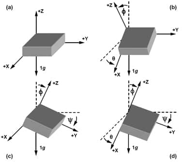
The microprocessor of the Wireless transmitter will capture the raw signal of 3-axis acceleration the calculate the tilt angle of X, Y, and Z. Here are the final output values of the device.
|
X Tilt value |
16-bit signed integer X_TILT_VALUE = X_TILT_VALUE_X10 / 10 Range: -90.0 to 90.0 |
|
Y Tilt value |
16-bit signed integer Y_TILT_VALUE = Y_TILT_VALUE_X10 / 10 Range: -90.0 to 90.0 |
|
Z Tilt value |
16-bit signed integer Z_TILT_VALUE = Z_TILT_VALUE_X10 / 10 Range: -90.0 to 90.0 |
AG Tilt Sensor's specification
| Sensing technology | MEMS acceleration |
| X/Y/Z tilt angle range | -90.0 to 90.0 degree |
|
Resolution |
0.01 o for AG-02 and 0.1 o for AG-01 |
| Repeatability | +/- 0.01 o for AG-02 and +/- 0.25 o for AG-01 |
| Within +/- 2.5 degrees of Tilt (for AG-02 version) | |
| Max Temperature drift | +/- 0.00065 o per oC |
| Max Non-linearity | +/- 0.0622 o |
| Total error in 20 oC deviation | +/- 0.075 o |
|
Parameter Measurement |
X tilt angle Y tilt angle Z tilt angle |
3. Calibration of the Daviteq AG Tilt Sensor
The Daviteq AG Tilt Sensor is calibrated at the factory. We highly recommend customers perform the offset adjustment on Software.
4. Application notes for the Daviteq AG Tilt Sensor
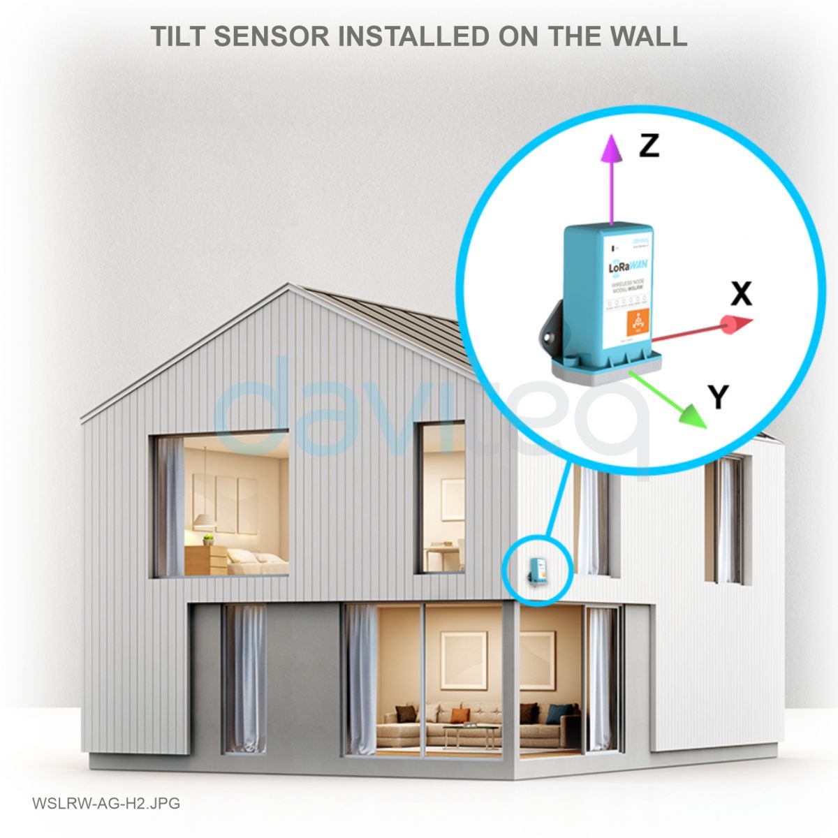
The Daviteq AG Tilt Sensor together with a wireless transmitter to be used to measure the Tilt angle of any object, for example:
- Tree;
- Bridge;
- Pole;
- Tower;
- Crane;
- Building...
 |
 |
 |
5. Installation
The AG sensor is built-in with the wireless transmitter. Therefore please refer to the installation procedure in the manual for the wireless transmitters.
6. Troubleshooting for the AG Tilt Sensor
| No. | Phenomena | Reason | Solutions | |
| 1 |
The wireless transmitter is still running and sending data, however, all the measurement parameters are not updated with new values |
1.1 | The connection between the AG tilt sensor and the wireless transmitter is broken! |
Please consult the manufacturer for a warranty or replacement. |
| 1.2 | The battery is almost draining off. | Check the battery status and replace it when necessary. | ||
| 2 | The measured values are not as expected | 2.1 | The installation direction is not correct. | Please recheck the installation. |
| 2.2 | The sensor is drifting. | Please consult the manufacturer for a warranty or replacement. | ||
| 3 | The reading values are very noisy even though the sensor is in a standstill position. | 3.1 | The sensor AG tilt sensor got a problem. | Please consult the manufacturer for a warranty or replacement. |
| 4 | From system: HW_Error = 1 | 4.1 | The lost connection between the sensor AG sensor and the wireless transmitter |
Please consult the manufacturer for a warranty or replacement. |
| 4.2 | The sensor AG sensor got a problem. | Please consult the manufacturer for a warranty or replacement. |
7. Maintenance of the AG Tilt Sensor
- There are no moving parts or consumed parts in the AG tilt Sensor. Therefore there is no need to do maintenance.
8. Default configuration
There is no configuration required for the AG tilt sensor. There is only configuration for the Wireless transmitter, please refer to the wireless transmitter's manual.
END.