Daviteq Sensing Technologies
- Daviteq Optical Sensing Technologies
- Daviteq Radar Sensing Technologies
- Daviteq Gas Detection Technologies
- Daviteq G4 Gas Sensor - Measurement Principle
- Daviteq GHC Flammable Gas Sensor - Measurement Principle
- Manual for AV10-G4-NH3 sensor for Livestock
- Hướng dẫn sử dụng cảm biến AV10-G4-NH3 dùng cho chăn nuôi
- Daviteq Electrical Sensing Technologies
- Daviteq Ultrasonic Level - Distance Measuring Technologies
- Daviteq Air / Gas Flow Measurement Technologies
- Daviteq Inertial Measurement Technologies
- Daviteq Pressure Measurement Technologies
- Daviteq Soil Measurement Sensors
Daviteq Optical Sensing Technologies
Daviteq LPC Lidar People Counter - Measurement Principle
1. Overview
Daviteq Lidar People Counter is a sensor with static lidar sensor with advanced and ultra-low-power MCU to perform the counting algorithm.
To detect a person passing thru the gate, it uses lidar to measure the distance from the sensor to the object. As the changes in distance, it will understand a person passing thru the gate. Moreover, it can distinguish the direction of movement.
Precise counting with ultra-low-power to save energy is a big challenge with Lidar technology. Therefore, Daviteq engineers had a smart decision to put the PIR sensor so that the sensor can wake up to count when there is human reach the sensor, in the Field of view (FOV) of the PIR Sensor. When there is no moving human body in the FOV of the PIR sensor, the sensor will go to sleep mode for energy saving. When it detects the moving human body, it will wake up immediately to count people, the delay time of wake up is about 20ms.
When there is no moving human body, it will fall back to sleep mode within 20ms.
2. Detail measurement principle
Counting people with this Lidar sensor consists of using the multiple zones of the sensor receiving area, and configuring it with two distinct fields of view (FoV), to alternatively get a ranging distance from them and consequently recognize the movements of a person. Using this method, the number of people occupying a meeting room, accessible from reasonably narrow access, is known at all times by detecting the entrances and exits of the attendees.
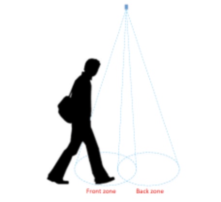
By measuring and analyzing the distances of targets within the FoVs of a front and back zone (see figure below), an algorithm can detect the direction a person crosses the area under the two FoVs. This algorithm "understands" that someone is under one of the FoV as long as the distance measured by the sensor under this FoV is between 0 and a threshold value specified in mm.
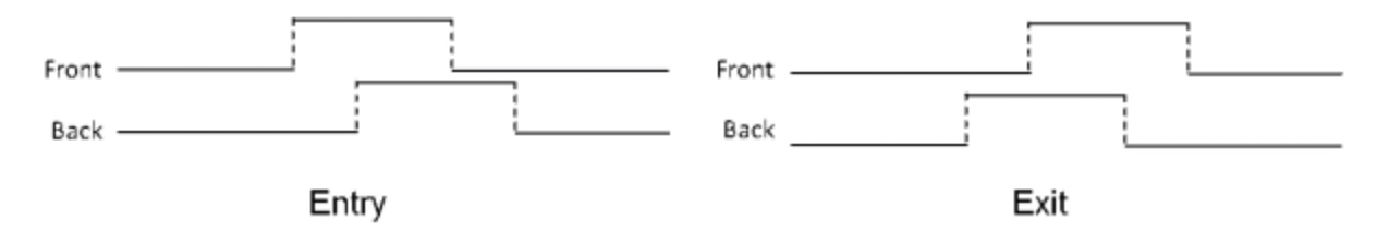
From a timing perspective, the sensor alternatively ranges on each of the two zones, for a very short period of milliseconds. It is possible to determine in which direction a person crosses the area, depending on in which order this person has been detected in the two zones, as shown in the figure below.
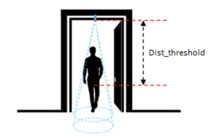
Dist_threshold mechanism
- The sensor will measure the distance from the sensor (on the ceiling) to the floor, when there is an obstacle, the person is under the sensor, the sensor will measure the distance from the sensor to the obstacle, and that person => will get the DistX value
- When DistX < Dist_threshold, the sensor detects that someone is standing below
- When DistX > Dist_threshold + dist_hys, the sensor confirms that no one is under
Counting Hysteresis
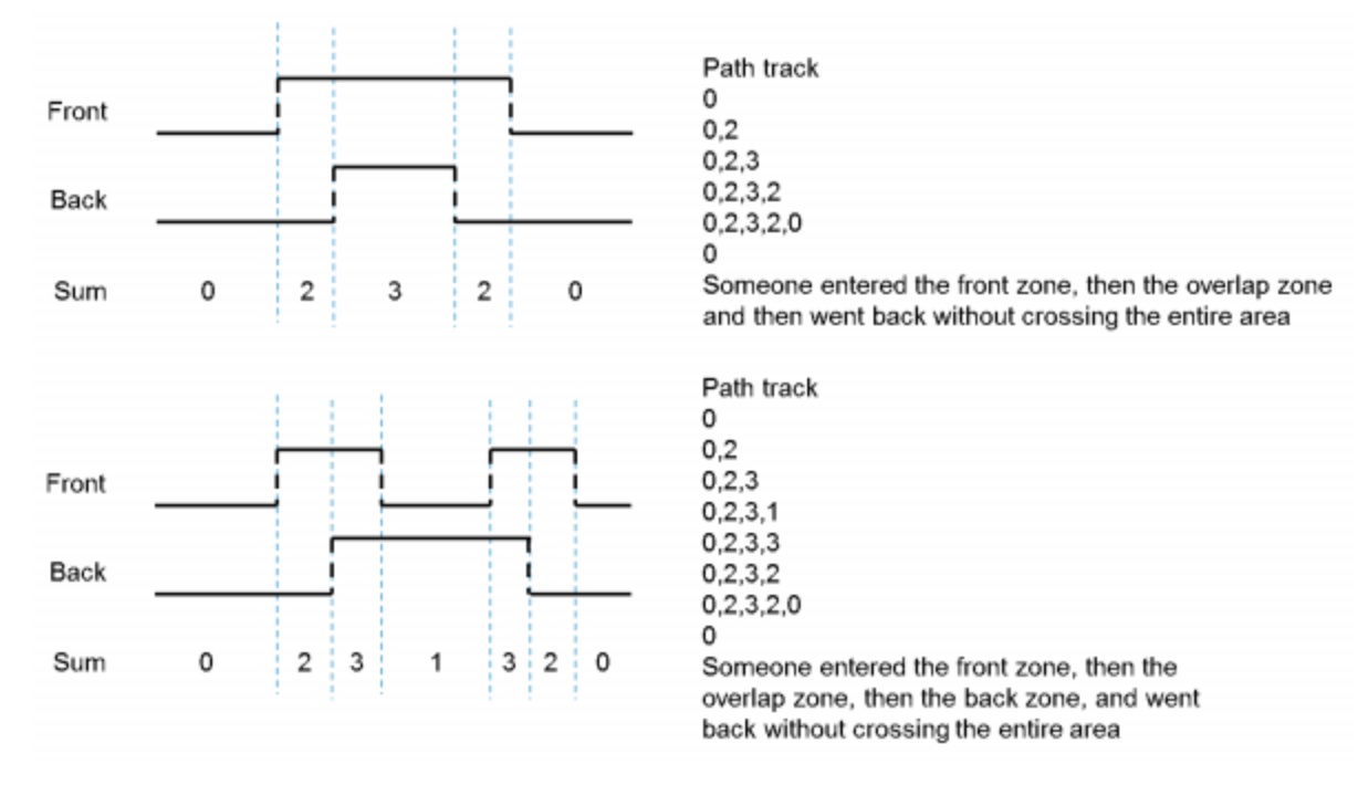
The algorithm validates a crossing event only when a person has fully crossed the two zones. It does not validate the event when the person remains for a long time under the FoV or when the person decides to return from the place he came from, and hence the counting values are not changed.
3. Commissioning (calibration) the Daviteq Lidar People Counter
Commissioning the sensor is an important step to getting the sensor working properly.
The Lidar FOV is 27 degrees and the max distance is 3500mm, so please check the width and height dimensions of the gate so that the person must be within the FOV;
After that, checking the floor, the floor must be a flat and bright color. The very dark color (back or near-black color) floor can affect the distance measurement accuracy. In this case, using a light color carpet to gain accuracy;
The reliability of the algorithm relies on the accuracy of the setup which detects the distance between the sensor and the floor. This can be ensured only if nothing (e.g. no obstacle or static object) blocks the front and back FoVs. To assess if a setup is reliable, a significant number of distances can be measured with the sensor. Then, a histogram diagram can be established to confirm that the sensor is correctly set up and that no target is within its FoVs.
A threshold needs to be defined, which is achieved after having ranged the flooring material over a significant number of samples. In fact, the threshold should be chosen so that all the measured distances (when ranging the floor) are greater than this threshold. We recommend that at the installation of the application, the autocalibration routine is launched to calculate the threshold. This is because flooring material can be different in many locations.
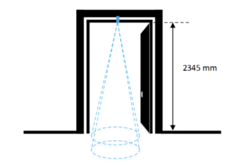
Figure 2.3: The distance between the sensor and the floor is 2345 mm, and as the minimum distance measured by the sensor is 2290 mm, the threshold is thus less than 2290 mm.
Notes:
- This calibration should be performed in the worst ambient light conditions, to maximize the jitter and obtain a threshold that is relevant to all possible ambient lighting conditions the counting setup is exposed to;
4. Application notes for Daviteq Lidar People Counter
The Daviteq Lidar People Counter can be used to count people using the public toilet or going to a store, office room, or meeting room…
The sensor will be mounted on the top of the gate or walkway with the sensor facing down to the floor. It can be used for the gate or walkway with dimensions as below:
- Width is from 700 to 1500mm
- Height is from 2000 to 3500mm
The sensor can count people passing thru the gate in both directions, it can distinguish the direction. However, if people walk too fast or run thru the gate, it cannot count that people, therefore the counting value will be missing.
* Walking speed limit: < 1.38 m/s (5 km/hr)
Notes:
- The sensor is intended for indoor application only, not applied for outdoor as the direct sunlight will saturate the measurement of the sensor.
- The color of the floor must be bright enough so that the laser ray can reflect the sensor. If the floor was too dark like dark brown, dark gray, or black color, the sensor would not work properly.
- The sensor can only count one person by one. If there were more than one person passing thru the gate at the same time or if they walk closely together, the sensor would count as one. Therefore, the counting value will be missing.
ATTENTION:
- DO NOT INSTALL THE SENSOR OUTDOOR OR INDOORS WITH HIGH INTENSITY OF SUNLIGHT;
- DO NOT INSTALL THE SENSOR AT A PLACE WHERE HIGH DUST PARTICLES OR STEAM AFFECT THE OPTICAL SENSOR;
- DO NOT INSTALL THE SENSOR AT A PLACE NEAR A DOOR AS THE DOOR WILL BLIND THE PIR SENSOR, IT WILL NOT WAKE UP THE SENSOR TO COUNT PEOPLE;
- DO NOT INSTALL THE SENSOR AT A PLACE WHERE THE PEOPLE MOVING IN PARALLEL AND NEARBY THE SENSOR, THAT WILL CAUSE THE SENSOR TO WAKE UP ALL THE TIME, BUT NOT FOR COUNTING PEOPLE. THIS PROBLEM WILL MAKE THE BATTERIES DRAIN OFF QUICKLY IN A FEW DAYS.
5. Troubleshooting for Daviteq Lidar People Counter
| No. | Phenomena | Reason | Solutions | |
| 1 | It does not count at all or the Count values are inaccurate | 1.1 | Low battery, the device does not run | Check battery |
| 1.2 | The PIR malfunctions, it cannot detect moving people to wake up the sensor | Put the ear nearby sensor to hear the sound of sizzling? if there is no sound, the PIR sensor or complete sensor got failure, please consult the manufacturer. | ||
| 1.3 | The walking speed to fast, higher than 1.38m/s | Walk at normal speed | ||
| 1.4 | The person does not walk in the FOV of the Lidar sensor (27 degrees cone) | Check the installation and dimension of the Gate | ||
| 1.5 | Wrong threshold setting | Commissioning the sensor again as part 3. | ||
| 1.6 | Sensor error, sensor error code is not Zero. | Please consult the manufacturer | ||
| 1.7 | The optical lens of the Lidar sensor got dirty or malfunction | Check and clean the optical lens with alcohol (70% volume) | ||
6. Maintenance of the sensor
This Lidar people counter comprises 02 optical parts:
- Lidar sensor with optical lense;
- PIR sensor with lense;
These 02 parts need to be checked and cleaned periodically, depending on the environment.
Use alcohol (70% volume) to clean the surface of the 2 above parts.
After cleaning, force the sensor to send data to check the distance values of the Front and Back zones to confirm the accuracy of distance measurement.
Do not use Acetone or other strong solvents to clean, it will destroy the surface of the sensor and cause malfunctions
7. Default configuration
Please find below the default configuration. You can change the configuration to suit the requirement of specific applications as in section 3 above.
| Description | Unit | Default | Format | Property | Comment |
| distThreshold | mm | 1600 | uint16 | Read / Write | Threshold setting for laser sensor to distinguish between when people are present and when no one is standing under the sensor The laser sensor will measure the distance value from the sensor (ceiling) to the floor.
|
| distHys | mm | 100 | uint16 | Read / Write | Hys of distThreshold |
| inter_meas_period | ms | 48 | uint16 | Read / Write | The sampling time of the sensor laser |
Daviteq Radar Sensing Technologies
Daviteq Gas Detection Technologies
Daviteq G4 Gas Sensor - Measurement Principle
1. Introduction
1.1 Overview
Daviteq G4 Gas sensor module is a gas measuring module that utilizes the Seri-4 electrochemical sensor with a high sensitivity to low concentrations of detected gas, high selectivity, and a stable baseline. It has an ultra-low noise amplifier to amplify the nano-ampere current signal from the sensor and delivers the stable and high-resolution output to the reading devices such as Sub-GHz transmitter, Sigfox transmitter, LoRaWAN transmitter, RS485 output transmitter, etc.
The module can support various types of gas sensors such as CO, NO, NO2, H2S, NH3, O2, O3, SO2, Cl2, HCHO...
Typical Applications: Gas, toxic gas detecting, air quality monitoring for facility, building, pump station, HVAC...
* For some applications with high humidity ambient all the time, the sensor can come with a heater to control the humidity within the working range of the sensor.
1.2 Specification
| Sensor technology | Seri-4 electrochemical gas sensor. Please check this link for the specifications of each gas type. |
| Sensor housing / Rating | SS316/SS304 housing with 316SS sintered filter / for Indoor use (buy the optional accessory rain-guard for outdoor installation) |
Note: Do not install the sensor where the ambient humidity is higher than 90% RH most of the time! It will cause the sensor to malfunction.
1.3 Cross Sensitivity Data
What is cross-sensitivity?
The electrochemical sensor is normally affected by other gas. It meant the sensor not only measure the target gas but also the other gases. If there is a concentration of other gas, it would also cause the change in sensor output with a factor listed in the below table.
Please check the cross-sensitivity data of each gas type in this link.
2. Detail measurement principle
The very low current from the gas sensor is amplified by a special amplifier circuit to deliver stable and high resolution.
The special mechanism provides noise filtering so that it can deliver a very stable output. The ADC chip can provide a resolution from 16-bit to 24-bit.
The circuit will deliver the digital output to the reading device.
With an ultra-low-power design, it can run by battery for 10-20 years!
The G4 sensor module will deliver 02 values:
- Gas concentration, in ppm or ppb.
- The temperature of the circuit board, in oC.
3. Calibration of the Daviteq G4 Gas Sensor
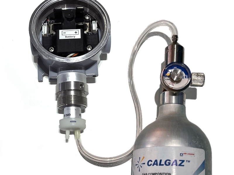
The Daviteq G4 Gas Sensor must be connected to a reading device, normally it is a wireless transmitter like Sub-GHz, Sigfox, or LoRaWAN.
In the reading device, the following parameter is configured in advanced:
Sensor+amplifier sensitivity (mV/ppm): it is the voltage output of the amplifier circuit = Sensor current output (nA/ppm) x R_gain
For example, with an NH3 gas sensor, the default value of the Sensor current output is 110nA/ppm and R_gain = 100 Kohms.
Therefore, the default NH3 Sensor+amplifier sensitivity = 11 mV/ppm
Depending on the sensor type and R_gain value, the sensor sensitivity must be calculated and pre-configured into the reading device.
3.1 Why do we need to calibrate the gas sensor? There are some reasons:
- The sensor current output of a sensor is different from the other sensor. It is not the same value for all sensors after manufacturing.
- The sensor current output of a sensor will be changed over time. For example, the NH3 sensor current output will be reduced by about 5% of the signal per six months in clean air at 25 oC temperature.
- The R_gain of the circuit also has a 0.1% or 0.05% tolerance;
Therefore, users need to calibrate the sensor before use or in a pre-defined interval time (6 or 12 months for example).
3.2 How to calibrate the G4 Gas sensor?
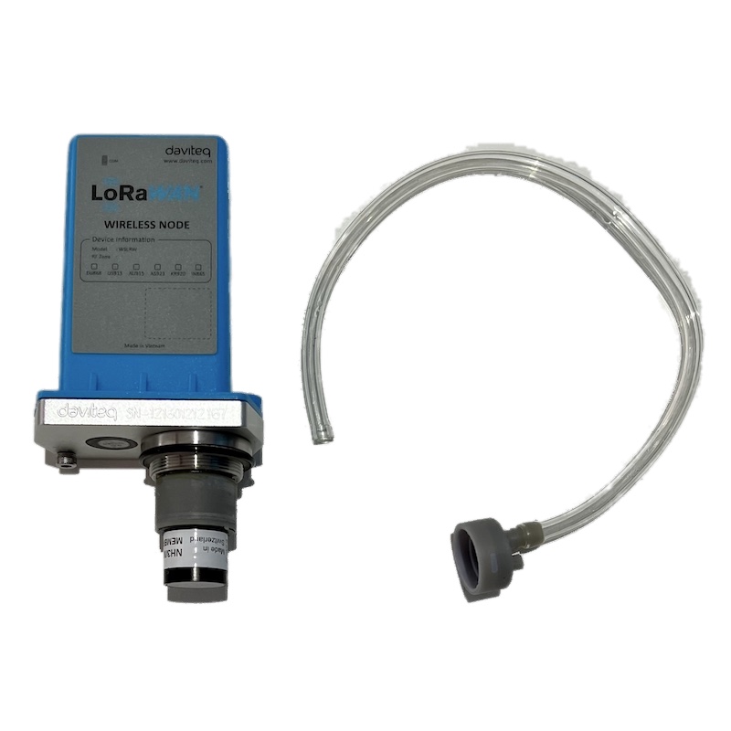
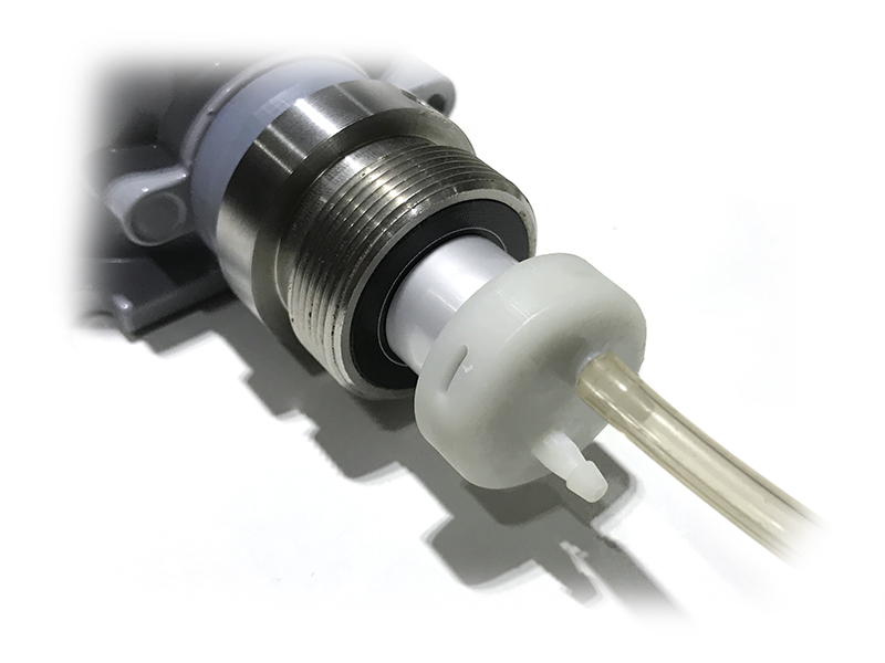
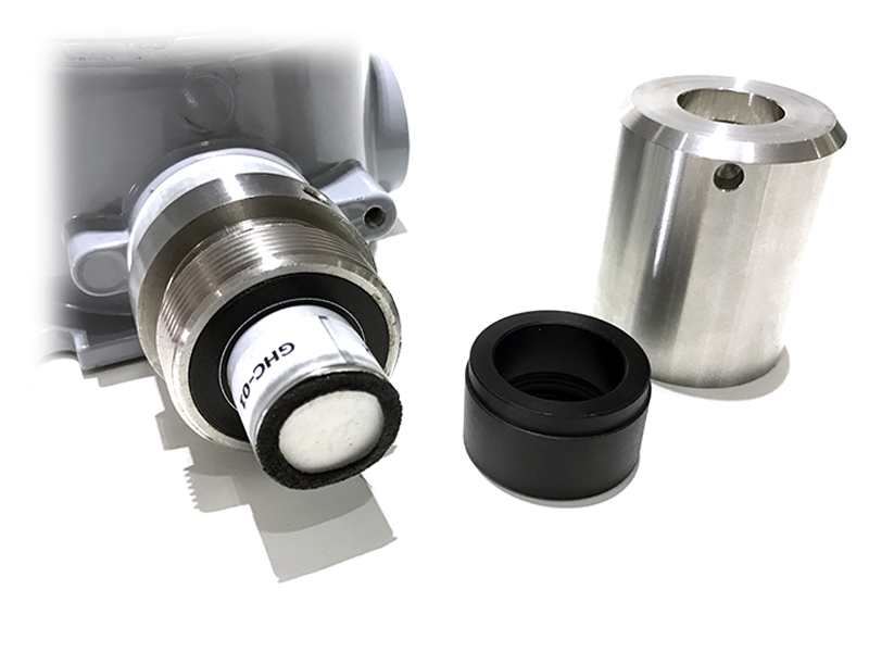
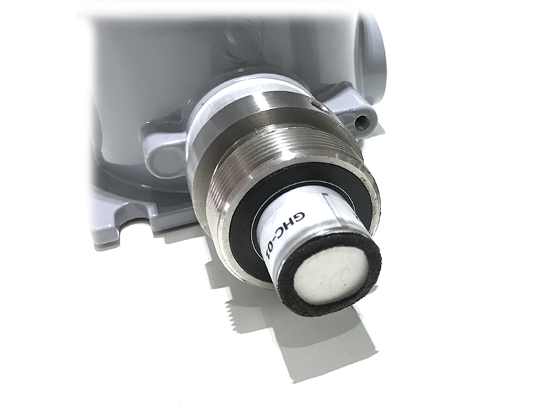
Instructions to attach the calibration cap onto the sensor module to get Zero or Span values.
|
Step 1. Remove the Filter and prepare the calibration cap
|
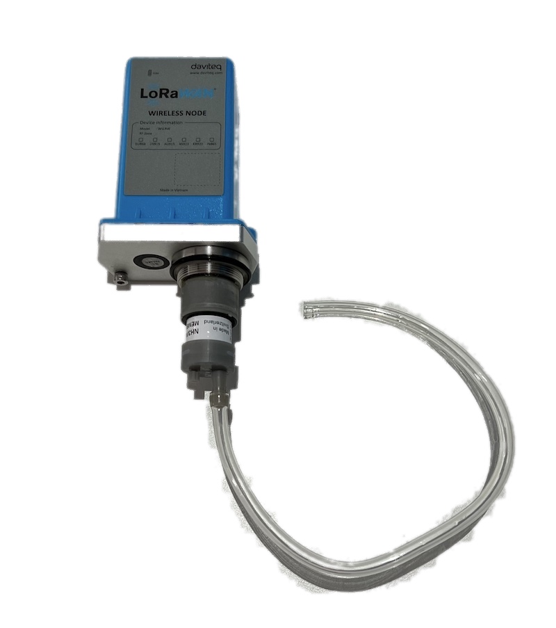
Step 2. Attach the calibration cap to the sensor head
|
|
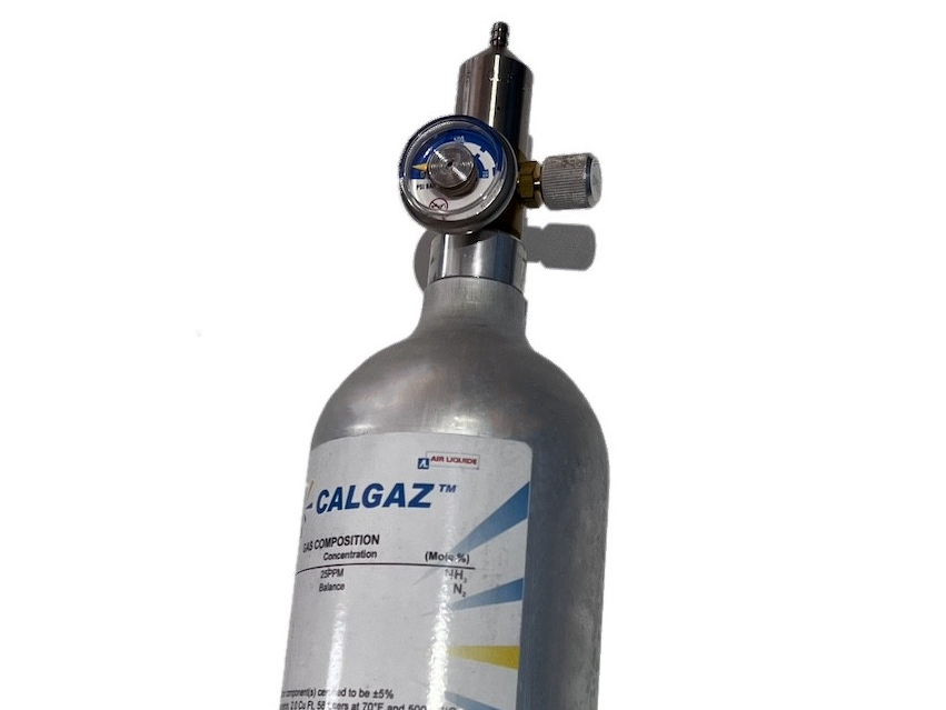
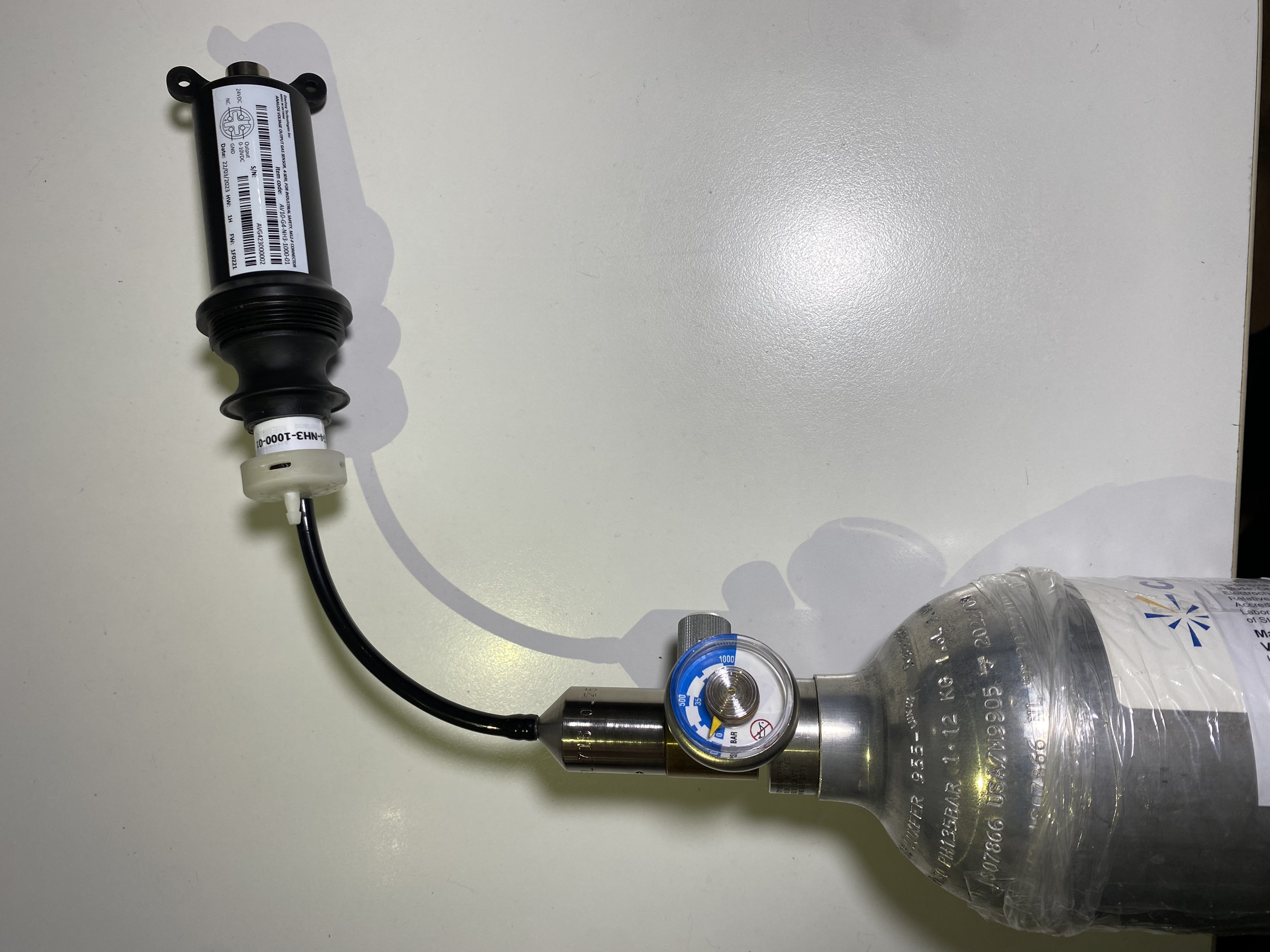
Step 3. Installed the Regulator to the Gas cylinder
|
Step 4. Attach the tube to the regulator
|
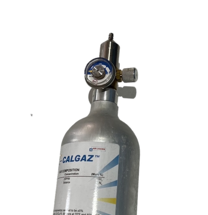
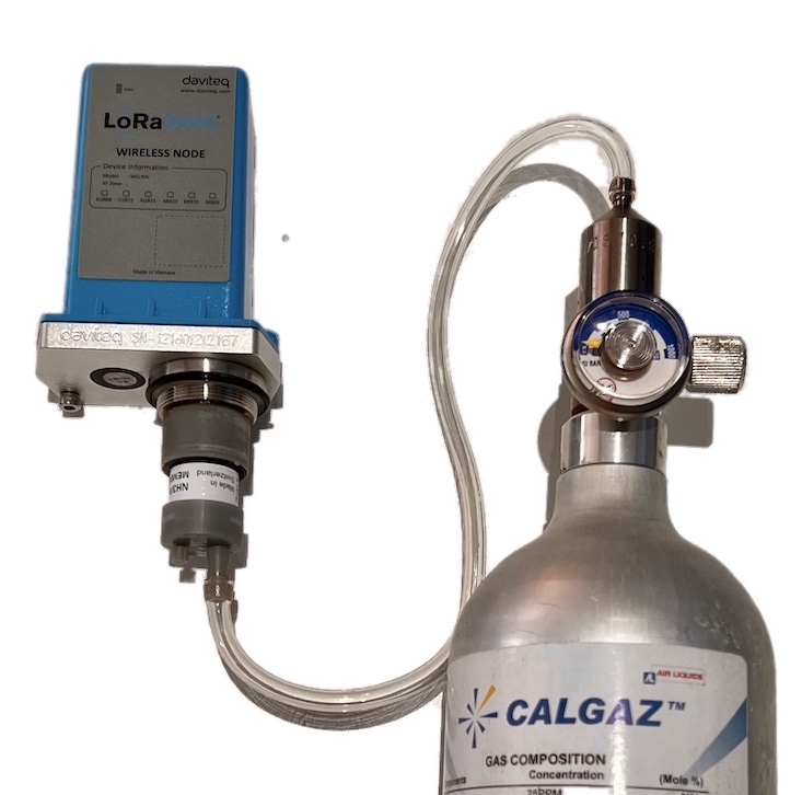
Please use the Flow Regulator with a flow rate of 2.5 LPM or 5.0 LPM.
With the 2-point calibration method, the user can define the A and B factors. Please find below the steps of calibration.
Step 1: Get the Zero value.
- Power ON the device;
- Place the device in a clean-air environment (the target value is nearly zero) at a temperature from 20 - 30 oC, in at least 60 minutes. It is better to use the 99.99% Nitrogen gas as zero gas instead of clean air.
- After 60 minutes, force the device to send data, read and record the Raw_value.
- Recommendation: Record many Raw values at least 10 minutes apart (10 values).
Zero value is the average of the recorded Raw values
Note: the Raw_value can be positive or negative; it will be in the range of -3.00 to +3.00 ppm
Step 2: Get the Span value
Note: Keep the sensor Power ON all the time;
- Use the standard gas cylinder with a known concentration (for example NH3 in N2 with a concentration of 25ppm or 50ppm) to supply the gas to the sensor;
- Use the calibration cap as above pictures to attach to the sensor and connect the tubing to the gas cylinder;
- Open the valve on the Cylinder slowly and make sure the gas has reached the sensor. Please use the Flow regulator 2.5 LPM or 5.0 LPM.
Notes:
- The tube length is short as possible to reduce the gas loss.
- Press a timer to start counting the time;
- After 2 minutes, force the device to send data once every minute, and stop forcing at 5 minutes. The highest Raw_value is the Span value.
Note: Just get one value for Span
- After that, immediately turn OFF the valve to save the gas;
- Remove the calibration cap from the sensor;
- Place the sensor in clean air again.
Note: Always keep the sensor Power ON all the time;
DO NOT PLACE THE SENSOR IN THE SPAN GAS FOR MORE THAN 5 MINUTES; IT WILL SATURATE THE SENSOR OUTPUT AND DEGRADE THE SENSOR LIFE QUICKLY.
Step 3: Calculate the new A and B
-The calculation of new A, B value based on basic linear formula: y = A * x + B
Where:
A, B is calibration coefficients
x is the sensor process value (example gas level in ppm) read on reading device (RAW_VALUE in the payload) such as on application server/network server, on offline tool
y is the correct value. y is the value of standard gas/standard condition
Which condition of Zero value: y0=A * x0 + B
Which condition of Span value: ys=A * xs+ B
From the two formulas, the calculation of A, B as below
A = (y0 - ys) / (x0 - xs)
B = (ys * x0 - y0 * xs)/ (x0 - xs)
-Example of A, B calculation for LoraWAN Ammonia Gas sensor (item code WSLRW-G4-NH3-100-01):
* With condition of clean-air environment at a temperature from 20 - 30 oC, there is no ammonia gas (y0 = 0); while the NH3 level on reading device (RAW_VALUE in the payload) is -0.25 (x0 = -0.25)
* When the sensor is connected to standard gas cylinder having ammonia level of 25 ppm (ys = 25); while the NH3 level on reading device (RAW_VALUE in the payload) is 18.66 (xs = 18.66)
*The calculation of A, B for the Ammonia gas sensor:
A = (0 - 25) / (-0.25 - 18.66) =1.32205
B = (ys * x0 - y0 * xs)/ (x0 - xs) = (25 * (-0.25) - 0 * 18.66)/ (-0.25 - 18.66) = 0.33051
The factory default A = 1 and default B = 0
Use RAW_VALUE in the payload on the reading device for calibration
Step 4: Configure the new A and B into the device
- User can use the off-line tool or downlink to write the values of A and B;
- Writing the new A and B successfully meant you had done the calibration process. Congratulation!
4. Application notes for the Daviteq G4 Gas Sensor
Depending on what type of gas sensor is used in the G4 gas module, the applications will be different. Please refer for some applications:
| Gas type | Typical applications |
| NH3 Ammonia Gas | NH3 leakage detection for HVAC, Chiller... NH3 concentration in the toilet NH3 concentration in the animal farms; chicken, pig, cow... NH3 concentration in the ambient air (Air quality monitor) |
| H2S |
H2S gas monitor for the sewage treatment system H2S gas monitor for basement floor H2S gas monitor for solid waste treatment plant... |
| Cl2 Chlorine gas |
Chlorine gas leakage detection in the chemical process plant Chlorine gas monitoring in ambient air in the water treatment plant Chlorine toxic gas monitoring in the City ... |
5. Installation notes
Notes:
* Avoid the place with humidity higher than 90% RH all the time (a short time in 2-3 days is acceptable)
* if the Sensor is intended to install outdoors, please use a rain guard to protect the sensor from rain and direct sunlight. Please contact us to buy this accessory.
- Place the sensor in the area to monitor the target gas concentration. Please always check the gas molecular weight v.s the air.
- For example, NH3 gas has a lighter weight than air, so the sensor must be placed at a height higher than the source of NH3 leakage. Normally, the sensor will be mounted at a height of 1.6m from the ground.
- For NH3 Odor detection in the toilet, users can place the sensor from 1.6m on the wall or on the ceiling which a height <= 2.6m
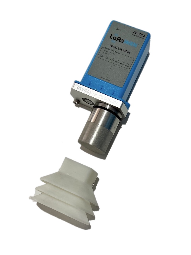
Note for Outdoor installation: For outdoor installation, please use the Rain guard to protect the sensor from raindrops or snowflakes. Please find below the steps of installation
|
Step 1. Prepare the rain guard.
|
Step 2. Insert rain guard to the sensor filter and tighten the locking screws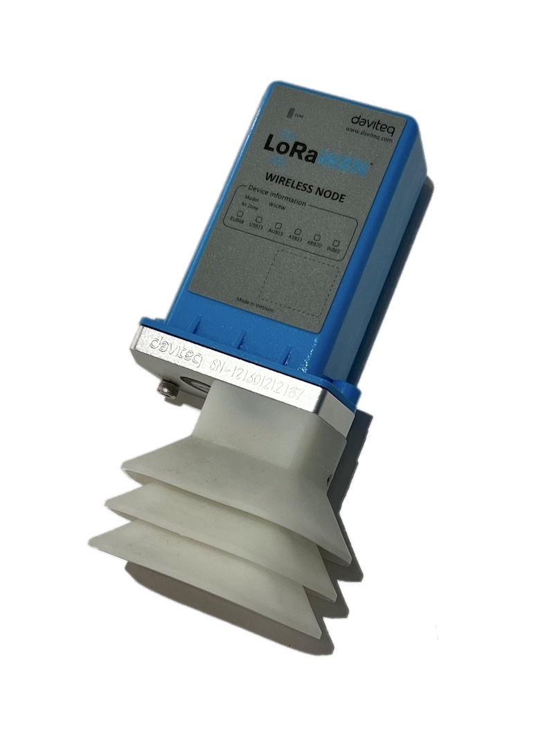 |
6. Troubleshooting for the Daviteq G4 Gas Sensor
| No. | Phenomena | Reason | Solutions | |
| 1 | The measured value is not within the expected value. | 1.1 | The sensor is drifted by time. | Re-calibrate the sensor |
| 1.2 | The sensor was in a high humidity environment (> 90% RH) for more than 03 days continuously. | Place the sensor in low humidity for its recovery. It may take up to 30 days to recover. If the sensor cannot recover after 30 days, please replace the new sensor module. | ||
| 2 | The measured value is always zero or near zero. | 2.1 | The sensor module was removed. | Please check the sensor. |
| 2.2 | The sensor is at the end of its life. | Replace the sensor module | ||
| 3 | HW_Error = 1 | 3.1 | Loosed connection of sensor module and wireless transmitter. | Check the internal wiring. |
| 3.2 | The measuring module got a problem. | Please consult the manufacturer for a warranty or replacement. |
7. Maintenance of the Daviteq G4 Gas Sensor
| What? |
How? |
When? |
| Cleaning the Filter |
Check and clean the filter every few months, depending on the environment. Clean the filter with warm water and soap, then use compressed air to purge it from the inside out. |
Approx. 6-12 months |
| Re-calibration |
The gas sensor may be drifting over time. Please check the sensor specification to identify the interval time for the re-calibration sensor. Please follow the calibration procedure in section 3 above. |
Approx. 6-12 months |
| Sensor replacement |
Replace the new sensor module after 02 years of operation (please check the sensor specification of each gas type). Please see below instructions. |
Approx. 2 years |
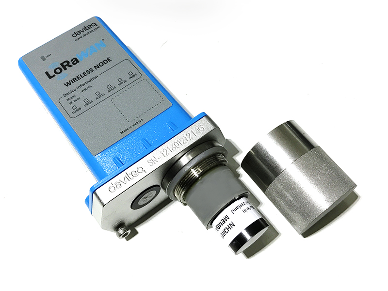
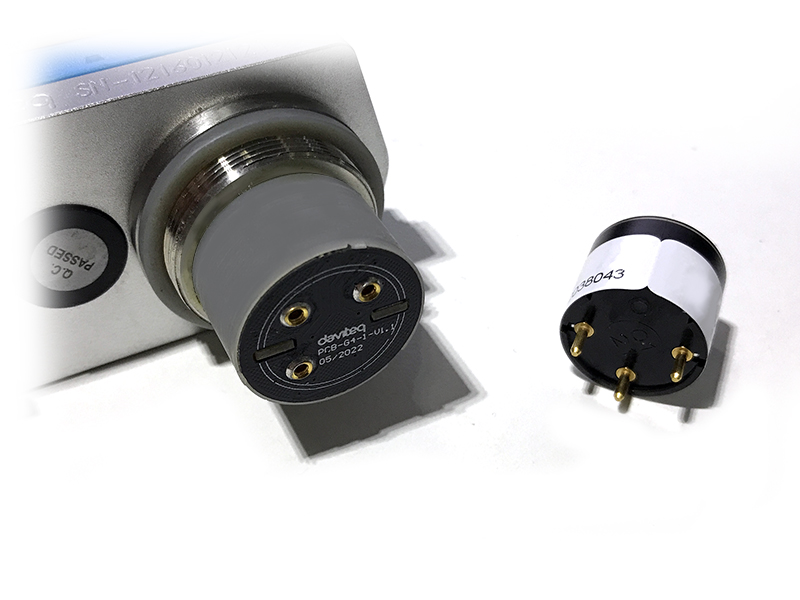
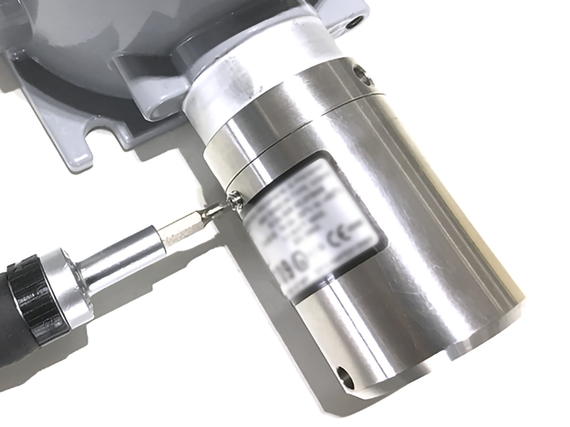
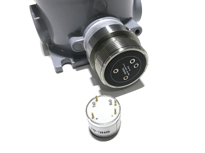
Sensor replacement instructions:
* Please remove the batteries before doing the following steps
|
Step 1. Remove the filter
|
Step 2. Unplug the sensor module
|
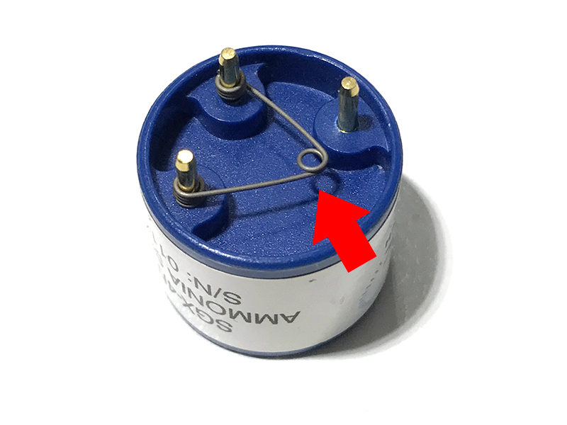
|
Step 3. Remove the spring clip on the new sensor module.
|
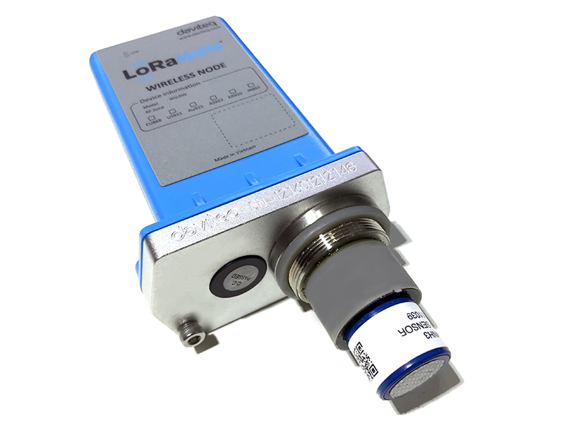
Step 4. Plug the new sensor module into the PCB
|
|
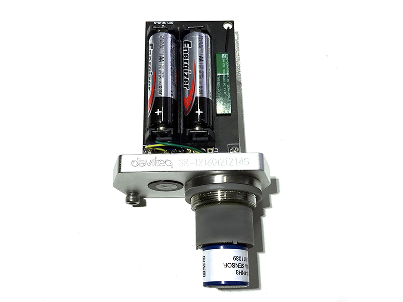
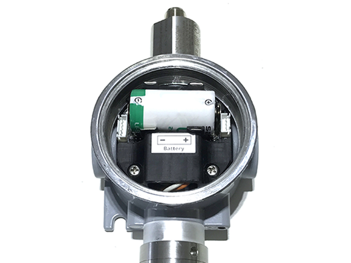
Step 5. Insert the batteries and start calibration of the new sensor as per section 3.
|
Step 6. Place the filter back.
|
8. Default configuration
This G4 gas sensor module has the default configuration, however, those parameters can be changed. The user can change the configuration on the wireless transmitter so that the complete sensor (transducer + wireless) delivers the proper output value. Below are some configuration parameters that store in the flash memory of the wireless transmitter.
| Description | Unit | Default | Format | Property | Comment |
| CONSTANT_A | 1 | Float | R/W |
Constant a for scaling measured value |
|
| CONSTANT_B | 0 | Float | R/W |
Constant b for scaling measured value |
|
| HIGH_CUT | 1E+09 | Float | R/W |
High cut value for scaled_value |
|
| LOW_CUT | 0 | Float | R/W |
Low cut value for scaled_value |
|
| SENSOR+AMPLIFIER SENSITIVITY | mV | Float | R/W |
Default = 11 for NH3 gas sensor |
END.
Daviteq GHC Flammable Gas Sensor - Measurement Principle
1. Introduction
1.1 Overview
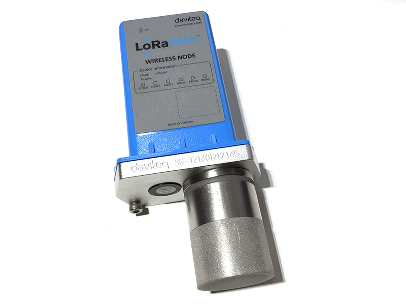
Daviteq GHC Gas sensor module is intended for the automatic continuous measurement of hydrocarbons or carbon dioxide concentration in the atmosphere. The sensor operating principle is based on NDIR technology, i.e. on selective absorption of LED-produced infrared radiation by gas molecules. The differential dual wavelength method allows the elimination of water vapor, optical elements contamination, and other non-selective hindrances influence.
It has ultra-low power consumption to allow it to be integrated with Wireless Devices such as Sub-GHz transmitter, Sigfox transmitter, LoRaWAN transmitter, RS485 output transmitters, etc.
It can be calibrated with target gas like CH4, C3H8, C2H4, and C2H6...
Typical Applications: Flammable gas detection.
1.2 Specification
| Sensor technology | LED-based NDIR |
| Gas sampling method | Diffusion |
| Sensor housing / Rating | SS316/SS304 housing with 316SS sintered filter / for Indoor use (buy the optional accessory rain-guard for outdoor installation), Exd approval for Zone 1 or Zone installation. |
| Target gas | CH4, CH4/CH4+C2H6, C3H8, C2H4,... please consult us for other HC gases |
| Ambient Humidity | 0 - 98% |
| Temperature | -40 .. + 60 oC |
| Atmospheric pressure | 80 .. 120 kPa |
| Warm-up time | 120 sec |
| Measurement range, % vol. | 0 .. 5% vol. CH4, 0 .. 100% vol. CH4, for other ranges please consult us |
| Reading Stability in +20 .. + 25 oC |
± 0.1% vol. or ± 5% of readings (whichever is greater) for CH4 ± 0.05% vol. or ± 5% of readings (whichever is greater) for C3H8 |
| Zero Stability in +20 .. + 25 oC |
for CH4: ± 0.1% vol. or ± 2% LEL |
| Response time T90 | <= 30 sec (with sintered metal filter) |
| Sensor lifetime | >= 10 years |
| Calibration interval | Recommend recalibrating zero and span at least every 30 months |
Detailed reading stability
| Calibration Gas |
Readings stability within a temperature range |
Additional variability due to pressure |
Additional variability due to humidity |
| CH4 |
± 0.1% vol. or ± 5% of readings (whichever is greater) within the range of +20...+25 °C; |
± 0.2% vol. or ± 30% of readings (whichever is greater) at 100 kPa (test: 80 kPa, 100 kPa, 120 kPa) |
± 0.2% vol. or ± 15% of readings (whichever is greater) at 40 °C (test: 20% RH, 50% RH, 90% RH) |
|
± 0.2% vol. or ± 10% of readings (whichever is greater) within the range of |
|||
|
± 0.4% vol. or ± 20% of readings (whichever is greater) within the range of |
|||
| C3H8 |
± 0.05% vol. or ± 5% of readings (whichever is greater) within the range of +20...+25 °C; |
± 0.1% vol. or ± 30% of readings (whichever is greater) at 100 kPa (test: 80 kPa, 100 kPa, 120 kPa) |
± 0.1% vol. or ± 15% of readings (whichever is greater) at 40 °C (test: 20% RH, 50% RH, 90% RH) |
|
± 0.1% vol. or ± 10% of readings (whichever is greater) within the range of |
|||
|
± 0.2% vol. or ± 20% of readings (whichever is greater) within the range of |
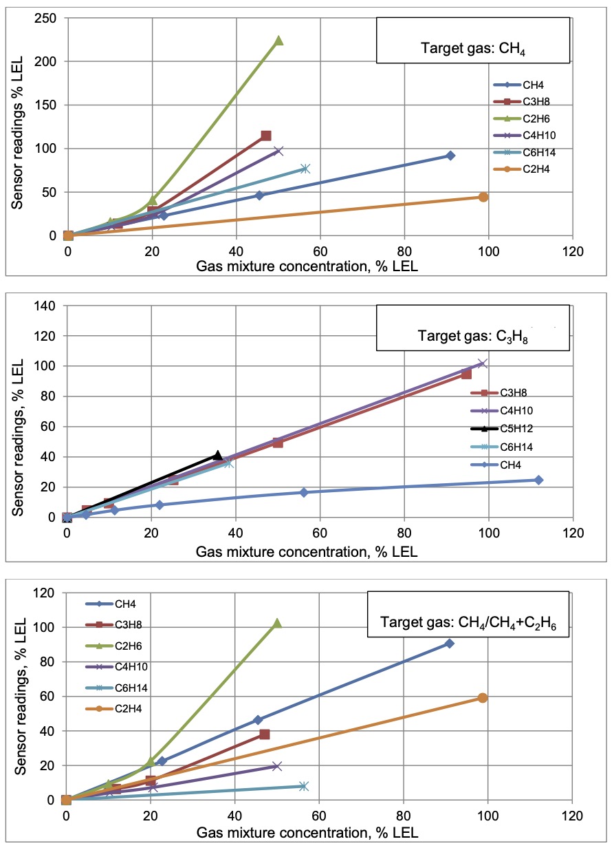
1.3 Cross-Sensitivity Data
What is cross-sensitivity?
The gas detection sensor is usually affected by other gas. It meant the sensor not only measure the target gas but also the other gases. If there is a concentration of additional gas, it would also cause a change in sensor output with a factor listed in the below table.
2. Principle of operation
When infrared radiation interacts with gas molecules, infrared light is absorbed by the gas molecules at a particular wavelength, causing vibration of the gas molecules. NDIR (Non-Dispersive Infrared) gas sensors detect a decrease in transmitted infrared light which is in proportion to the gas concentration. This transmittance, the ratio of transmitted radiation energy to incident energy, is dependent on the target gas concentration.
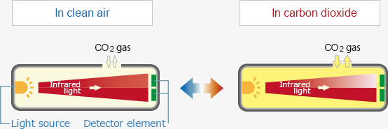
NDIR gas sensor consist of an infrared source, detector, optical filter, gas cell, and electronics for signal processing. A single light source, dual wavelength type gas sensor has two detectors and two optical filters of different wavelengths which are placed in front of each detector. The infrared light that is absorbed by a target gas passes through the active filter with a particular bandwidth for the detection of the target gas. The infrared light that does not interact with the target gas passes through the reference filter. The difference between transmitted light intensities in these two bandwidths is converted into gas concentration. The dual wavelength sensor ensures stable measurements for a long period of operation as the aging effects of the light source or the gas cell are automatically compensated by output signals at the reference wavelength.
Mid-infrared radiation through sample gas causes a resonance of gas molecules at their natural frequency with the infrared light in the spectrum region where the energy level of infrared is equivalent to the natural frequency of gas molecules, resulting in the absorption of infrared by gas molecules in the form of molecular vibration.
The relationship between infrared transmittance and gas concentration is expressed by the Lambert-Beer law:

Where T is transmittance, I is the intensity of light passed through sample gas and an optical filter, Io is the initial light intensity emitted from the source, ε is the molar attenuation coefficient, c is gas concentration, and d is the light path length.
Because ε of the target gas and the light pass length d are fixed with an NDIR sensor, gas concentration can be measured by measuring the transmittance within the spectrum region of the absorbed energy (wavelength) by the target gas.
The initial light intensity emitted from the light source Io is preset by calibration using zero gas which does not absorb infrared light. The initial value of the molar extinction coefficient ε is set by calibration using calibration gas of known concentration.
3. Calibration of the Daviteq GHC Gas Sensor
The Daviteq GHC Gas Sensor must be connected to a reading device, it usually is a wireless transmitter like Sub-GHz, Sigfox, or LoRaWAN.
3.1 Why do we need to calibrate the gas sensor? There are some reasons:
- The output value of a sensor is different from the other sensor. It is not the same value for all sensors after manufacturing.
- The output value of a sensor will be changed over time.
Therefore, users need to calibrate the sensor before use or in a pre-defined interval time (30 months for example).
3.2 How to calibrate the GHC Flammable Gas sensor?
NOTE: THE CALIBRATION CAN ONLY BE DONE IN THE SAFE ZONE!!!
Instructions to attach the calibration cap onto the sensor module to get Zero or Span values.
|
Step 1. Remove the Filter and prepare the calibration cap
|
Step 2. Attach the calibration cap to the sensor head
|
|
Step 3. Installed the Regulator to the Gas cylinder
|
Step 4. Attach the tube to the regulator
|
Please select the flow regulator with a flow rate of 2.5 LPM or 5.0 LPM.
With the 2-point calibration method, the user can define the A and B factors. Please find below the steps of calibration.
Step 1: Get the Zero value.
- Power ON the device;
- Place the device in a clean-air environment (the target value is nearly zero) at a temperature from 20 - 30 oC, in at least 60 minutes.
- After 60 minutes, force the device to send data, read and record the Raw_value, so now you got the Zero_value = Raw_GHC value.
Recommendation: Record many Raw_GHC values at least 10 minutes apart (10 values).
Zero value is the average of the recorded Raw values.
Note: the Raw_GHC values can be positive or negative; Its value is usually 7 (%LEL)
Step 2: Get the Span value
Note: Keep the sensor Power ON all the time;
- Use the standard gas cylinder with a known concentration (for example Eythylene Air 1.35% is equivalent to 50 %LEL ) to supply the gas to the sensor;
- Use the calibration cap as above pictures to attach to the sensor and connect the tubing to the gas cylinder;
- Open the valve on the Cylinder slowly and make sure the gas has reached the sensor. The flow regulator should be 2.5LPM or 5.0LPM.
Notes:
- The tube length is short as possible to reduce the gas loss;
- Press a timer to start counting the time;
- After 2 minutes, force the device to send data once every minute, and stop forcing at 5 minutes;
- The highest Raw_value is the Span value.
Note: just get one value for Span
- After that, immediately turn OFF the valve to save the gas;
- Remove the calibration cap from the sensor;
- Place the sensor in clean air again.
Note: Always keep the sensor Power ON all the time;
Step 3: Calculate the new A and B
-The calculation of new A, B value based on basic linear formula: y = A * x + B
Where:
A, B is calibration coefficients
x is the sensor process value (example gas level in ppm) read on reading device such as on application server/network server, on offline tool. The process value is the RAW_VALUE in the payload
y is the correct value. y is the value of standard gas/standard condition
Which condition of Zero value: y0=A * x0 + B
Which condition of Span value: ys=A * xs+ B
From the two formulas, the calculation of A, B as below
A = (y0 - ys) / (x0 - xs)
B = (ys * x0 - y0 * xs)/ (x0 - xs)
-Example of A, B calculation for LoraWAN Ammonia Gas sensor (item code WSLRW-G4-NH3-100-01):
* With condition of clean-air environment at a temperature from 20 - 30 oC, there is no ammonia gas (y0 = 0); while the NH3 level on reading device (RAW_VALUE in the payload) is -0.25 (x0 = -0.25)
* When the sensor is connected to standard gas cylinder having ammonia level of 25 ppm (ys = 25); while the NH3 level on reading device (RAW_VALUE in the payload) is 18.66 (xs = 18.66)
*The calculation of A, B for the Ammonia gas sensor:
A = (0 - 25) / (-0.25 - 18.66) =1.32205
B = (ys * x0 - y0 * xs)/ (x0 - xs) = (25 * (-0.25) - 0 * 18.66)/ (-0.25 - 18.66) = 0.33051
The factory default A = 1 and default B = 0
The RAW_VALUE in the payload is used for calibration
Step 4: Configure the new A and B into the device
- User can use the off-line tool or downlink to write the values of A and B;
- Writing the new A and B successfully meant you had done the calibration process. Congratulation!
4. Application notes for the Daviteq GHC flammable Gas Sensor
-
Do not use a damaged sensor. It must be repaired only by personnel authorized by the manufacturer.
-
Keep the sensor out of contact with aggressive substances e.g. acidic environments, which can react with metals, as well as solvents, which may affect polymeric materials.
-
Diffusion holes of the sensor should be protected against the ingress of sprayed liquid or waterdrops.
-
The sensor is not intended to measure the target gas concentration contained in fluids.
-
Correct measurement is provided when the ambient temperature changes not faster than 0.6 °C/min.
- Inspection and maintenance should be carried out by suitably trained personnel.
-
Persons, who have studied this UM, must be briefed on safety precautions when operating electrical equipment intended for use in explosive areas in due course.
-
When dealing with a cylinder containing a gas mixture under pressure, it is necessary to follow safety regulations.
-
There is no risk of pollution or negative impact on human health. The sensor does not contain any harmful substances that may be released during its normal operation.
5. Installation notes
Notes:
* If a sensor has been kept in transport containers at temperatures below zero centigrade, leave it at +10...+35 °C for not less than one hour.
* if the Sensor is intended to install outdoors, please use a rain guard to protect the sensor from rain and direct sunlight. Please contact us to buy this accessory.
- Place the sensor in the area to monitor the target gas concentration. Please always check the gas molecular weight v.s the air.
Note for Outdoor installation: For outdoor installation, please use the Rain guard to protect the sensor from raindrops or snowflakes. Please contact us to buy the Rainguard.
6. Troubleshooting for the Daviteq GHC Flammable Gas Sensor
| No. | Phenomena | Reason | Solutions | |
| 1 | The measured value is not within the expected value. | 1.1 | The sensor is drifted by time. | Re-calibrate the sensor |
| 1.2 | The sensor was spoiled. | Please consult the manufacturer for a warranty or replacement. | ||
| 2 | The measured value is always zero or near zero. | 2.1 | The sensor module was removed. | Please check the sensor. |
| 2.2 | The sensor is at the end of its life. | Replace the sensor module | ||
| 3 | HW_Error = 1 | 3.1 | Loosed connection of sensor module and wireless transmitter. | Check the internal wiring. |
| 3.2 | The measuring module got a problem. | Please consult the manufacturer for a warranty or replacement. |
7. Maintenance of the Daviteq GHC Flammable Gas Sensor
| What? |
How? |
When? |
| Cleaning the Filter |
Check and clean the filter every few months, depending on the environment. Clean the filter with warm water and soap, then use compressed air to purge it from the inside out. |
Approx. 6-12 months |
| Re-calibration |
The gas sensor may be drifting over time. Please check the sensor specification to identify the interval time for the re-calibration sensor. Please follow the calibration procedure in section 3 above. |
Approx. 30 months |
| Sensor replacement |
Replace the new sensor module only when the sensor cannot respond with standard calibration gas. |
> 10 years or when problem occurs. |
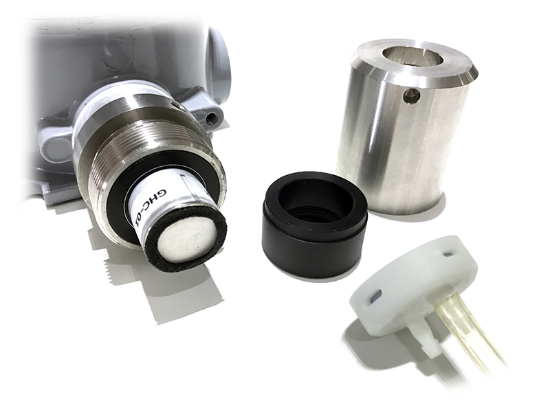
Sensor replacement instructions:
* Please remove the batteries before doing the following steps
|
Step 1. Unscrew the housing
|
Step 2. Remove the filter
|
|
Step 3. Unplug the sensor module
|
Step 4. Plug the new sensor module into the PCB
|
|
Step 5. Insert the batteries and start calibration of the new sensor as per section 3.
|
Step 6. Place the filter back.
|
8. Default configuration
This GHC gas sensor module has the default configuration, however, those parameters can be changed. The user can change the configuration on the wireless transmitter so that the complete sensor (transducer + wireless) delivers the proper output value. Below are some configuration parameters that store in the flash memory of the wireless transmitter.
| Description | Unit | Default | Format | Property | Comment |
| CONSTANT_A | 1 | Float | R/W |
Constant a for scaling measured value. This value would be changed after calibration. |
|
| CONSTANT_B | 0 | Float | R/W |
Constant b for scaling measured value. This value would be changed after calibration. |
|
| HIGH_CUT | 1E+09 | Float | R/W |
High cut value for scaled_value |
|
| LOW_CUT | 0 | Float | R/W |
Low cut value for scaled_value |
|
| SENSOR RESPONSE TIME | S | 100 | uint16 | R/W |
* Do not change this value |
| C_H_FACTOR | 4.4 | Float | R/W |
4.4 for CH4, 1.7 for C3H8 |
END.
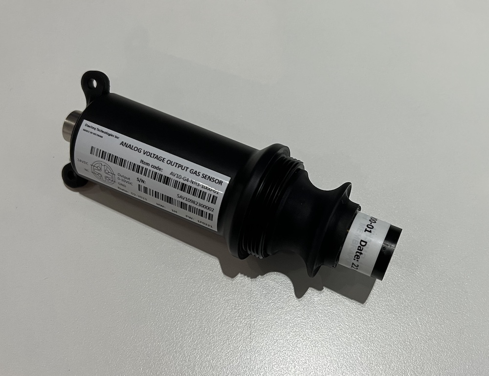
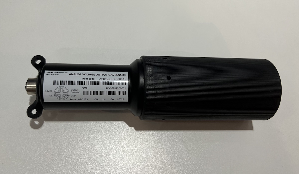
Manual for AV10-G4-NH3 sensor for Livestock
1. Introduction
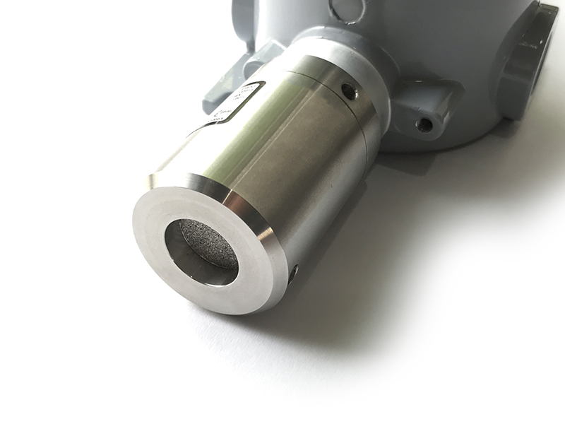
Daviteq NH3 Gas sensor for Livestock is a NH3 gas measuring sensor that utilizes the Seri-4 electrochemical sensor with a high sensitivity to low concentrations of detected gas, high selectivity, and a stable baseline. It has an ultra-low noise amplifier to amplify the nano-ampere current signal from the sensor and delivers the stable and high-resolution output.
* For some applications with high humidity ambient all the time, the sensor can come with a heater to control the humidity within the working range of the sensor.
2. Calibration of the Daviteq NH3 Gas Sensor
2.1 Why do we need to calibrate the gas sensor? There are some reasons:
- The sensor current output of a sensor is different from the other sensor. It is not the same value for all sensors after manufacturing.
- The sensor current output of a sensor will be changed over time. For example, the NH3 sensor current output will be reduced by about 5% of the signal per six months in clean air at 25 oC temperature.
- The R_gain of the circuit also has a 0.1% or 0.05% tolerance;
Therefore, users need to calibrate the sensor before use or in a pre-defined interval time (6 or 12 months for example).
2.2 How to calibrate the NH3 Gas sensor?
Instructions to attach the calibration cap onto the sensor module to get Zero or Span values.
|
Step 1. Remove the Filter and prepare the calibration cap
|
Step 2. Attach the calibration cap to the sensor head
|
|
Step 3. Installed the Regulator to the Gas cylinder
|
Step 4. Attach the tube to the regulator
|
Please use the Flow Regulator with a flow rate of 2.5 LPM or 5.0 LPM.
Step 1: Get the Zero value.
- Power ON the device;
- Place the device in a clean-air environment (the target value is nearly zero) at a temperature from 20 - 30 oC, in at least 60 minutes. It is better to use the 99.99% Nitrogen gas as zero gas instead of clean air.
- After 60 minutes, record the Voltage output value. Recording multiple values in 5 minutes to calculate the average value.
Step 2: Get the Span value
Note: Keep the sensor Power ON all the time;
- Use the standard gas cylinder with a known concentration (for example NH3 in N2 with a concentration of 25ppm or 50ppm) to supply the gas to the sensor;
- Use the calibration cap as above pictures to attach to the sensor and connect the tubing to the gas cylinder;
- Open the valve on the Cylinder slowly and make sure the gas has reached the sensor. Please use the Flow regulator 2.5 LPM or 5.0 LPM.
Notes:
- The tube length is short as possible to reduce the gas loss.
- Press a timer to start counting the time;
- After 2 minutes, record the voltage output, then record voltage output value again at the minute of 3, 4, and 5. Calculate the average output value of the minutes of 3, 4, and 5.
- After that, immediately turn OFF the valve to save the gas;
- Remove the calibration cap from the sensor;
- Place the sensor in clean air again.
Note: Always keep the sensor Power ON all the time;
DO NOT PLACE THE SENSOR IN THE SPAN GAS FOR MORE THAN 5 MINUTES; IT WILL SATURATE THE SENSOR OUTPUT AND DEGRADE THE SENSOR LIFE QUICKLY.
Step 3: Entering values to reading device
- After Zero and Span, you will get the voltage output correspond to zero gas and span gas value;
- Enter these values into your reading device (PLC...) to get correct reading.
3. Installation
Notes:
* Avoid the place with humidity higher than 90% RH all the time (a short time in 2-3 days is acceptable)
* if the Sensor is intended to install outdoors, please use a rain guard to protect the sensor from rain and direct sunlight. Please contact us to buy this accessory.
3.1 Level of Installation
- Place the sensor in the area to monitor the target gas concentration. Please always check the gas molecular weight v.s the air.
- For example, NH3 gas has a lighter weight than air, so the sensor must be placed at a height higher than the source of NH3 leakage. Normally, the sensor will be mounted at a height of 1.6m from the ground.
3.2 Wiring
Use the M12-Male cable Coding A, 4 pin as below picture.
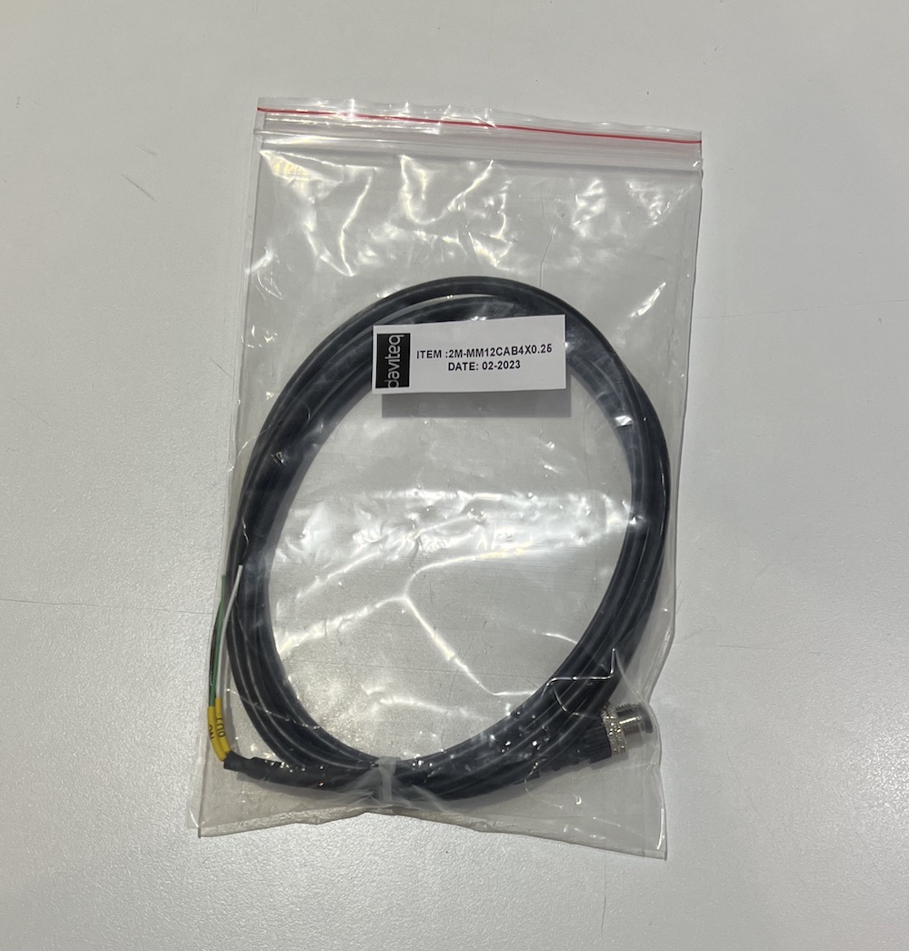
Because the Output is 0-10VDC, we do recommend to use the following cable for extention:
- Cable size: minimum 24AWG (or minimum 0.5 mm2 core)
- Cable type: Shielded
- Max recommended cable legnth: 20m
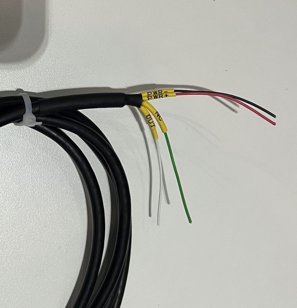
Connect the wires to Reading device as below:
- PWR+: 12-36VDC
- PWR-: GND
- OUT: 0-10VDC OUTPUT
- NC: Not used
Plug the M12 connector to sensor
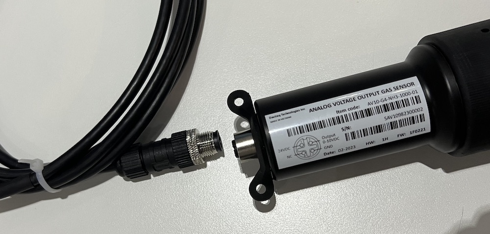
Firmly tighten the M12 connection:
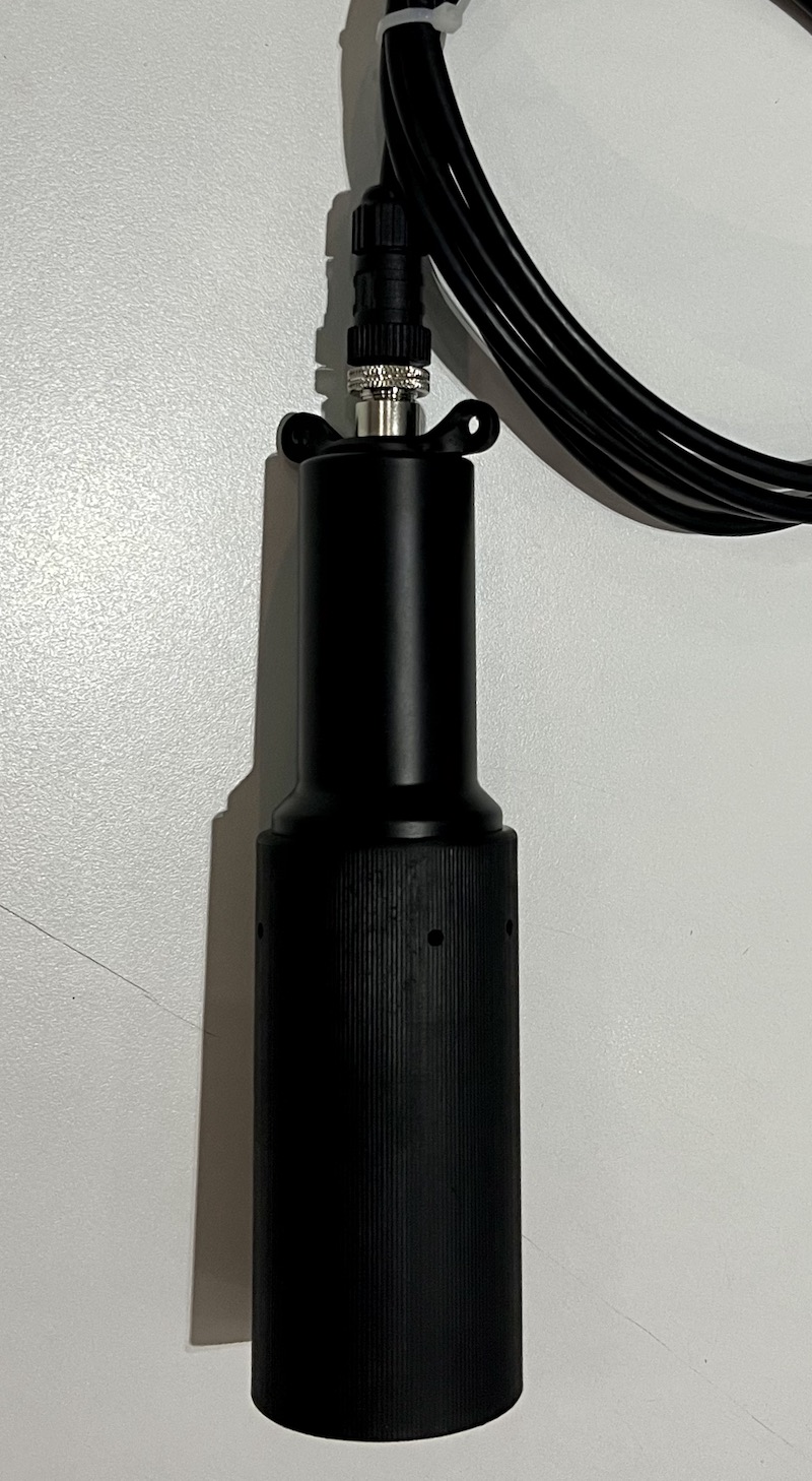
Recommend to use other rope (plastic rope or stainless steel rope) to hang the sensor, it will reduce the tension force of the signal cable.
4. Troubleshooting for the Daviteq NH3 Gas Sensor
| No. | Phenomena | Reason | Solutions | |
| 1 | The measured value is not within the expected value. | 1.1 | The sensor is drifted by time. | Re-calibrate the sensor |
| 1.2 | The sensor was in a high humidity environment (> 90% RH) for more than 03 days continuously. | Place the sensor in low humidity for its recovery. It may take up to 30 days to recover. If the sensor cannot recover after 30 days, please replace the new sensor module. | ||
| 2 | The measured value is always zero or near zero. | 2.1 | The sensor module was removed. | Please check the sensor. |
| 2.2 | The sensor is at the end of its life. | Replace the sensor module | ||
| 3 | The voltage output is 0V or random noise | 3.1 | The wiring problem | Check the wiring and connector M12. Check power supply. |
| 3.2 | The sensor is faulty | Contact manufacturer. |
5. Maintenance of the Daviteq NH3 Gas Sensor
| What? |
How? |
When? |
| Re-calibration |
The gas sensor may be drifting over time. Please check the sensor specification to identify the interval time for the re-calibration sensor. Please follow the calibration procedure as in above section. |
Approx. 6-12 months |
| Sensor replacement |
Replace the new sensor module after 1-2 years of operation (please check the sensor specification of each gas type). Please see below instructions. |
Approx. 1-2 years |
Sensor replacement instructions:
* Please disconnect the device before doing the following steps
|
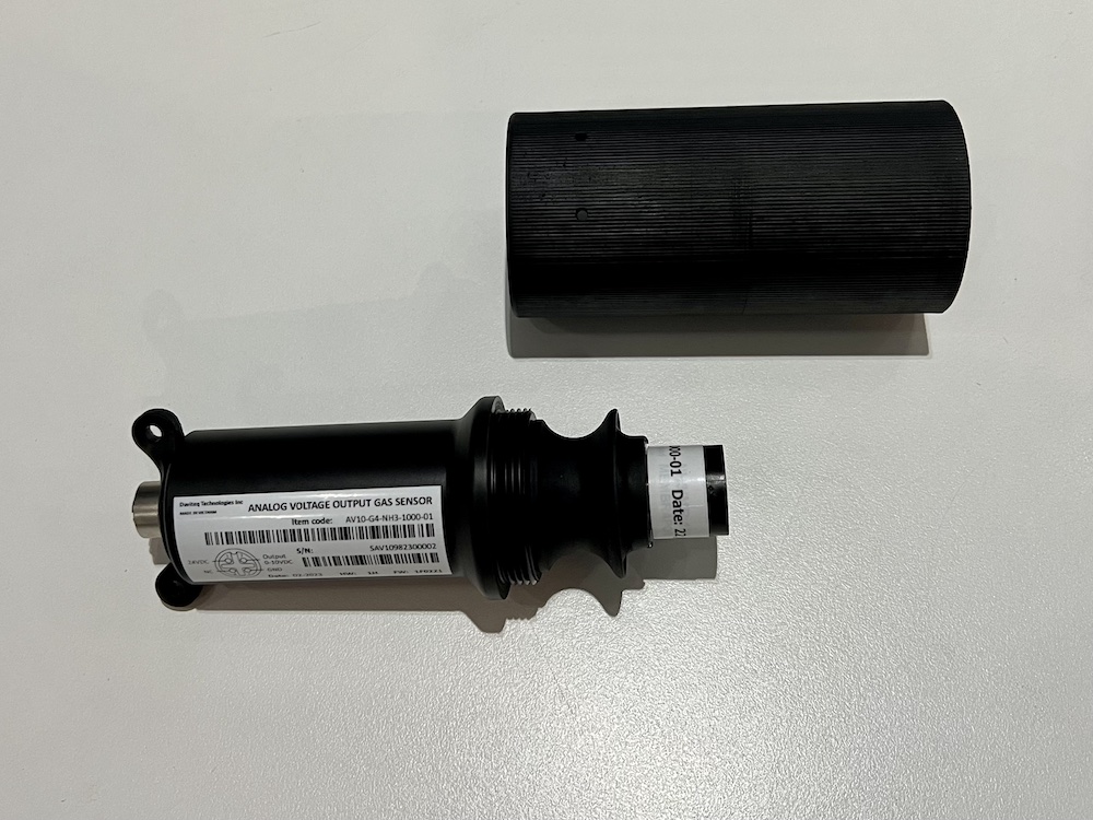
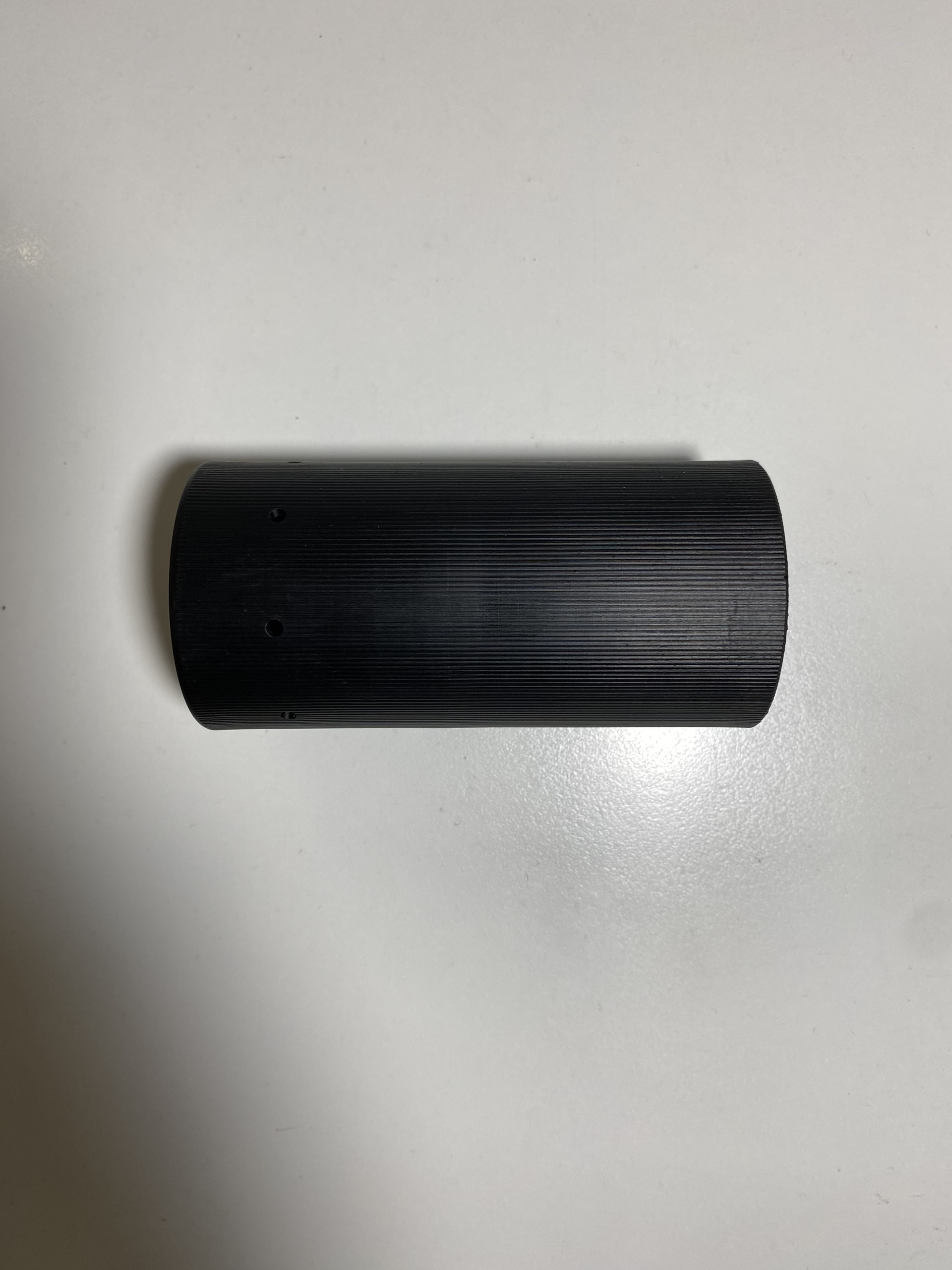
Step 1. Remove the Protector by Rotate it anti-clockwise
|
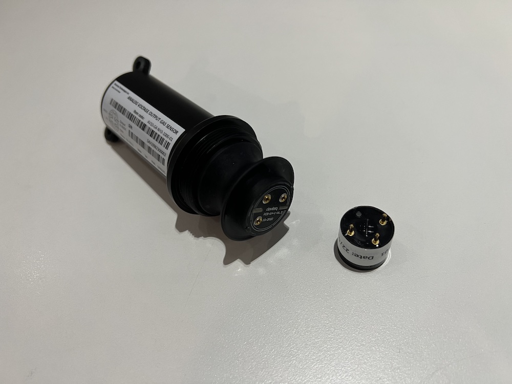
Step 2. Unplug the sensor module
|
|
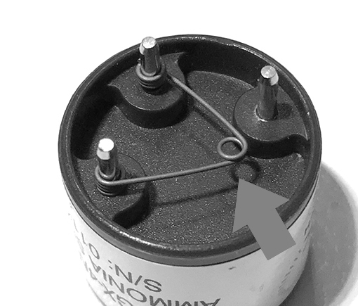
Step 3. Remove the spring clip on the new sensor module.
|
Step 4. Plug the new sensor module into the PCB
|
|
Step 5. Install the Protector back by Rotate it clock-wise
|
|
END.
Hướng dẫn sử dụng cảm biến AV10-G4-NH3 dùng cho chăn nuôi
1. Giới thiệu
Cảm biến khí NH3 của Daviteq dùng cho Chăn nuôi là thiết bị đo nồng độ khí NH3 sử dụng cảm biến điện hóa Seri-4 với độ nhạy cao, có thể phát hiện chính xác khí NH3 với nồng độ thấp, độ chọn lọc cao và ổn định. Thiết bị sử dụng bộ khuếch đại có độ nhiễu cực thấp để khuếch đại tín hiệu dòng điện nano-ampe từ cảm biến cho tín hiệu đầu ra có độ phân giải cao và đáng tin cậy.
*Đối với một số ứng dụng luôn ở trong môi trường độ ẩm cao, cảm biến có thể đi kèm với bộ sưởi để kiểm soát độ ẩm trong phạm vi hoạt động của cảm biến.
2. Hiệu chuẩn cảm biến khí NH3 Daviteq
2.1 Tại sao cần hiệu chuẩn cảm biến khí? Dưới đây là 1 số lí do:
- Tín hiệu dòng điện ra của mỗi cảm biến là khác nhau. Tất cả cảm biến đều có giá trị không đồng nhất sau khi sản xuất.
- Tín hiệu dòng điện ra của cảm biến sẽ thay đổi theo thời gian. Ví dụ, dòng điện đầu ra của cảm biến NH3 sẽ giảm khoảng 5% mỗi sáu tháng trong không khí sạch ở nhiệt độ 25 oC.
- Các linh kiện bo mạch cũng có sai số 0,1% hoặc 0,05%;
Do đó, người dùng cần hiệu chuẩn cảm biến trước khi sử dụng hoặc sau mỗi khoảng thời gian sử dụng (6 hoặc 12 tháng).
2.2 Hướng dẫn hiệu chuẩn cảm biến khí NH3 Daviteq
Hướng dẫn gắn nắp hiệu chuẩn vào mô-đun cảm biến để lấy giá trị Zero hoặc Span.
|
Bước 1. Tháo phần bảo vệ và chuẩn bị dụng cụ hiệu chuẩn
|
Bước 2. Gắn nắp hiệu chuẩn vào mô-đun cảm biến
|
|
Bước 3. Lắp van điều áp vào bình khí chuẩn
|
Bước 4. Kết nối cảm biến vào bình khí chuẩn
|
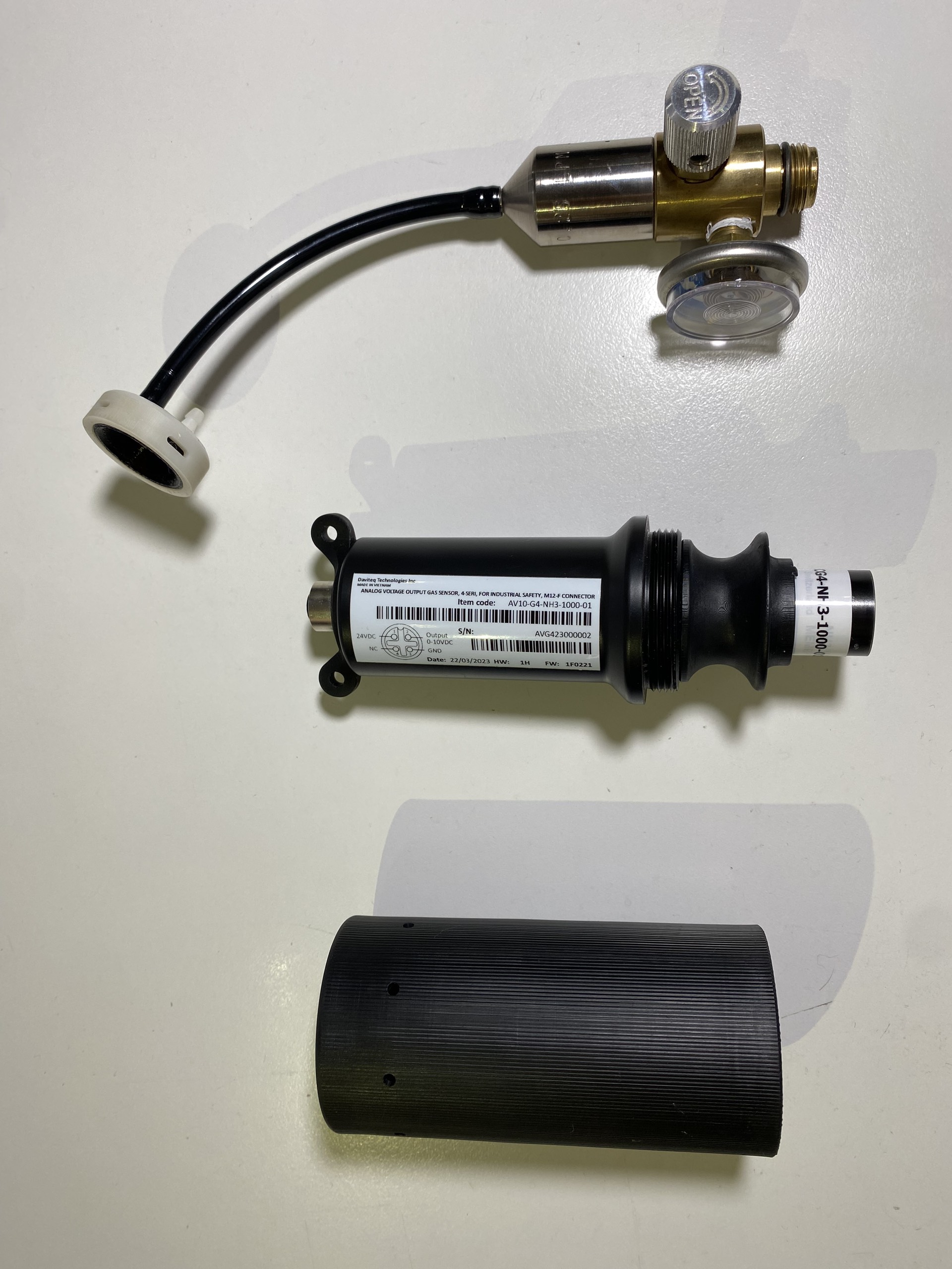
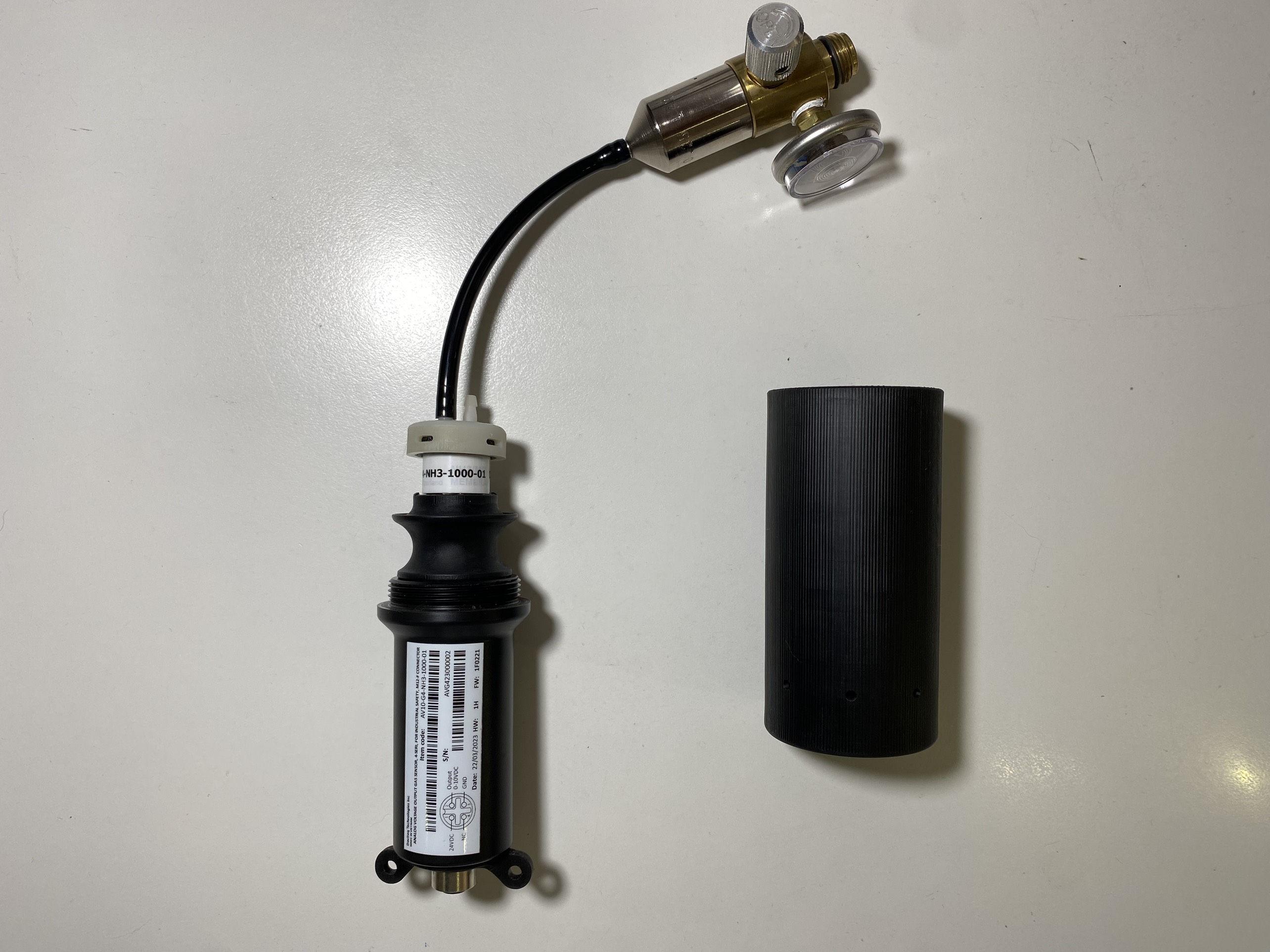
Lưu ý: Sử dụng Bộ điều áp với lưu lượng là 0,25 LPM hoặc 0.5 LPM.
Bước 1: Lấy giá trị Zero.
- Cấp nguồn thiết bị bằng cáp M12 kèm theo.
- Đặt thiết bị trong môi trường không khí sạch (để giá trị gần như bằng 0) ở nhiệt độ từ 20 - 30oC, trong ít nhất 60 phút. Khuyến cáo sử dụng khí Nitơ 99,99% để lấy giá trị Zero chính xác nhất thay vì không khí sạch.
- Ghi nhận giá trị đầu ra sau 60 phút. Lấy nhiều giá trị sau mỗi 5 phút và tính giá trị trung bình.
Bước 2: Lấy giá trị Span
Lưu ý: Không ngắt nguồn thiết bị trong quá trình thực hiện
- Sử dụng bình khí chuẩn với nồng độ định sẵn (ví dụ NH3 trong N2 có nồng độ 25ppm hoặc 50ppm) để cấp khí cho cảm biến;
- Dùng nắp hiệu chuẩn như hình trên để gắn vào cảm biến và nối ống với bình chứa khí;
- Mở van trên bình khí từ từ và đảm bảo khí được lưu thông đến cảm biến. Vui lòng sử dụng van điều áp 0,25 LPM hoặc 0,5 LPM.
Khuyến cáo: Nên sử dụng ống dẫn khí với chiều dài ngắn để giảm thất thoát khí.
- Bắt đầu bấm giờ để đánh dấu mốc thời gian.
- Sau 2 phút, ghi nhận điện áp ra, sau đó ghi lại giá trị điện áp ra ở các phút thứ 3, 4, 5. Tính giá trị trung bình ngõ ra ở các phút 3, 4, 5.
- Sau đó lập tức đóng van điều áp để tiết kiệm khí.
- Tháo nắp hiệu chuẩn khỏi thiết bị
- Đặt thiết bị về lại vùng không khí sạch.
Lưu ý: Không ngắt nguồn thiết bị trong quá trình thực hiện
KHÔNG CẤP KHÍ CHUẨN VÀO CẢM BIẾN QUÁ LÂU (>5PHÚT), SẼ GÂY BÃO HÒA VÀ GIẢM TUỔI THỌ MÔ-ĐUN CẢM BIẾN.
Bước 3: Nhập các giá trị vào thiết bị đọc
- Sau quá trình Zero và Span, ta sẽ có các giá trị điện áp tương ứng với mức khí Zero và Span.
- Nhập các giá trị này vào các thiết bị đọc (PLC,...) để có các kết quả điện áp chính xác.
3. Hướng dẫn lắp đặt
Lưu ý:
* Tránh để thiết bị làm việc liên tục ở môi trường có độ ẩm cao (>90% RH) trong thời gian dài (hơn 3 ngày).
* Nếu thiết bị được lắp đặt ngoài trời, vui lòng sử dụng tấm che mưa để bảo vệ cảm biến khỏi mưa và ánh nắng trực tiếp. Vui lòng liên hệ với NSX để mua phụ kiện này.
3.1 Độ cao lắp đặt
- Đặt thiết bị tại khu vực cần theo dõi nồng độ khí. Hãy luôn kiểm tra trọng lượng phân tử khí cần đo so với không khí.
- Ví dụ khí NH3 có trọng lượng nhẹ hơn không khí nên cảm biến phải đặt ở độ cao cao hơn nguồn phát sinh NH3. Thông thường, cảm biến sẽ được gắn ở độ cao 1,6m so với mặt đất.
3.2 Đấu dây
Thiết bị sử dụng cáp M12 đầu Đực Code A 4 lõi như hình dưới:
Vì thiết bị xuất tín hiệu 0-10VDC nên khuyến cáo nên sử dụng dây cáp mở rộng với đặc điểm sau:
- Loại dây có bọc chống nhiễu, tối thiểu 24AWG (hoặc lõi tối thiểu 0,5 mm2)
- Chiều dài dây tối đa: 20m
Kết nối dây với thiết bị đọc như sau:
- PWR+: 12-36VDC
- PWR-: GND
- OUT: 0-10VDC OUTPUT
- NC: Not used
Cắm đầu nối M12 vào cảm biến
Siết chặt kết nối M12:
Nên sử dụng dây khác (dây rút nhựa hoặc dây thép không gỉ) để treo cảm biến, như vậy sẽ làm giảm lực căng của dây cáp tín hiệu.
4. Khắc phục sự cố cho Cảm biến khí NH3 Daviteq
| STT | Hiện tượng | Nguyên nhân | Giải pháp | |
| 1 | Giá trị đo được không nằm trong giá trị mong đợi. | 1.1 | Cảm biến bị trôi theo thời gian. | Hiệu chuẩn lại cảm biến |
| 1.2 | Thiết bị được lắp đặt trong môi trường độ ẩm cao (> 90% RH) liên tục hơn 3 ngày. | Đặt thiết bị ở nơi có độ ẩm thấp để cảm biến phục hồi. Có thể mất tới 30 ngày để hồi phục. Nếu cảm biến không thể phục hồi sau 30 ngày, vui lòng thay mô-đun cảm biến mới. | ||
| 2 | Giá trị đo được luôn bằng hoặc gần bằng 0. | 2.1 | Mô-đun cảm biến mất kết nối với bo mạch | Vui lòng kiểm tra lại kết nối Mô-đun cảm biến với bo mạch. |
| 2.2 | Cảm biến bị hư hỏng | Thay Mô-đun cảm biến. | ||
| 3 | Điện áp ra luôn bằng 0 hoặc bị nhiễu | 3.1 | Lỗi đấu dây |
Kiểm tra lại dây đấu nối và cáp M12. Kiểm tra lại nguồn cấp. |
| 3.2 | Lỗi thiết bị | Vui lòng liên hệ trực tiếp NSX. |
5. Bảo dưỡng Cảm biến khí NH3 Daviteq
| What? |
How? |
When? |
| Hiệu chuẩn lại |
Cảm biến khí có thể bị trôi theo thời gian. Vui lòng kiểm tra các thông số kỹ thuật của cảm biến để xác định khoảng thời gian hiệu chuẩn lại. Quy trình hiệu chuẩn như ở phần trên. |
Sau khoảng 6-12 tháng |
| Thay thế mô-đun cảm biến |
Thay thế mô-đun cảm biến mới sau 1-2 năm hoạt động (vui lòng kiểm tra thông số kỹ thuật cảm biến của từng loại khí). Vui lòng xem hướng dẫn bên dưới. |
Sau khoảng 1-2 năm |
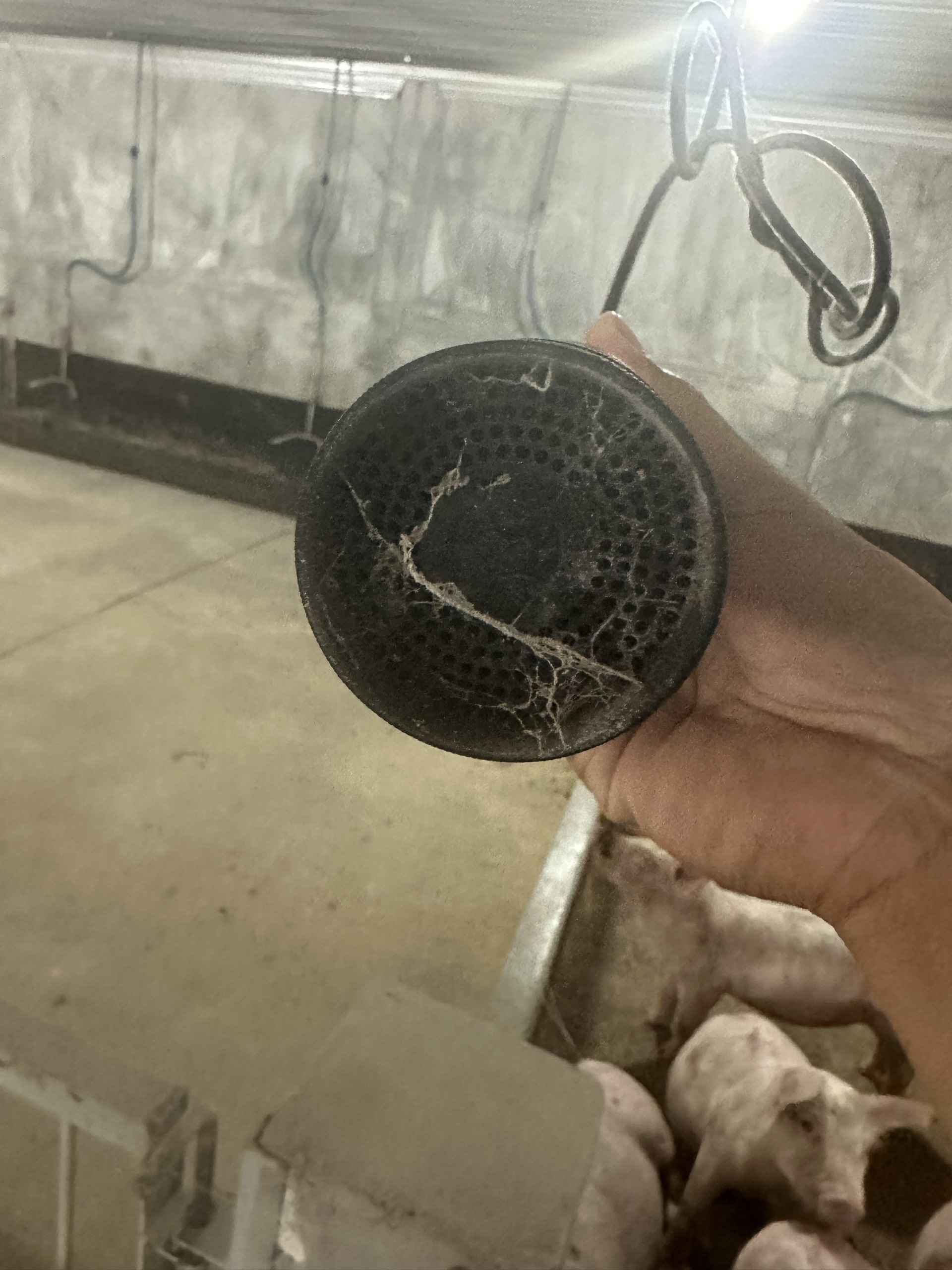
| Vệ sinh chụp bảo vệ cảm biến |
Cần kiểm tra và vệ sinh chụp bảo vệ cảm biến để đảm bảo khí lưu thông dễ dàng vào module cảm biến bên trong, giúp cảm biến đo chính xác. Vui lòng xem hướng dẫn bên dưới. |
Sau khoảng 3-6 tháng |
Quy trình thay thế mô-đun cảm biến:
Vui lòng ngắt kết nối thiết bị trước khi thực hiện.
|
Bước 1. Tháo tấm bảo vệ bằng cách vặn phần vỏ bảo vệ ngược chiều kim đồng hồ
|
Bước 2. Tháo mô-đun cảm biến khỏi bo mạch
|
|
Bước 3. Tháo kẹp lò xo trên mô-đun cảm biến mới
|
Bước 4. Cắm mô-đun cảm biến mới vào bo mạch
|
|
Bước 5. Lắp lại vỏ bảo vệ bằng cách vặn theo chiều kim đồng hồ
|
|
Quy trình vệ sinh thiết bị:
Cần vệ sinh chụp bảo vệ cảm biến định kỳ mỗi 3-6 tháng để đảm bảo cảm biến đo chính xác không khí môi trường xung quanh.
Vui lòng ngắt kết nối thiết bị trước khi thực hiện.
|
Bước 1. Tháo vỏ bảo vệ bằng cách vặn phần vỏ ngược chiều kim đồng hồ
|
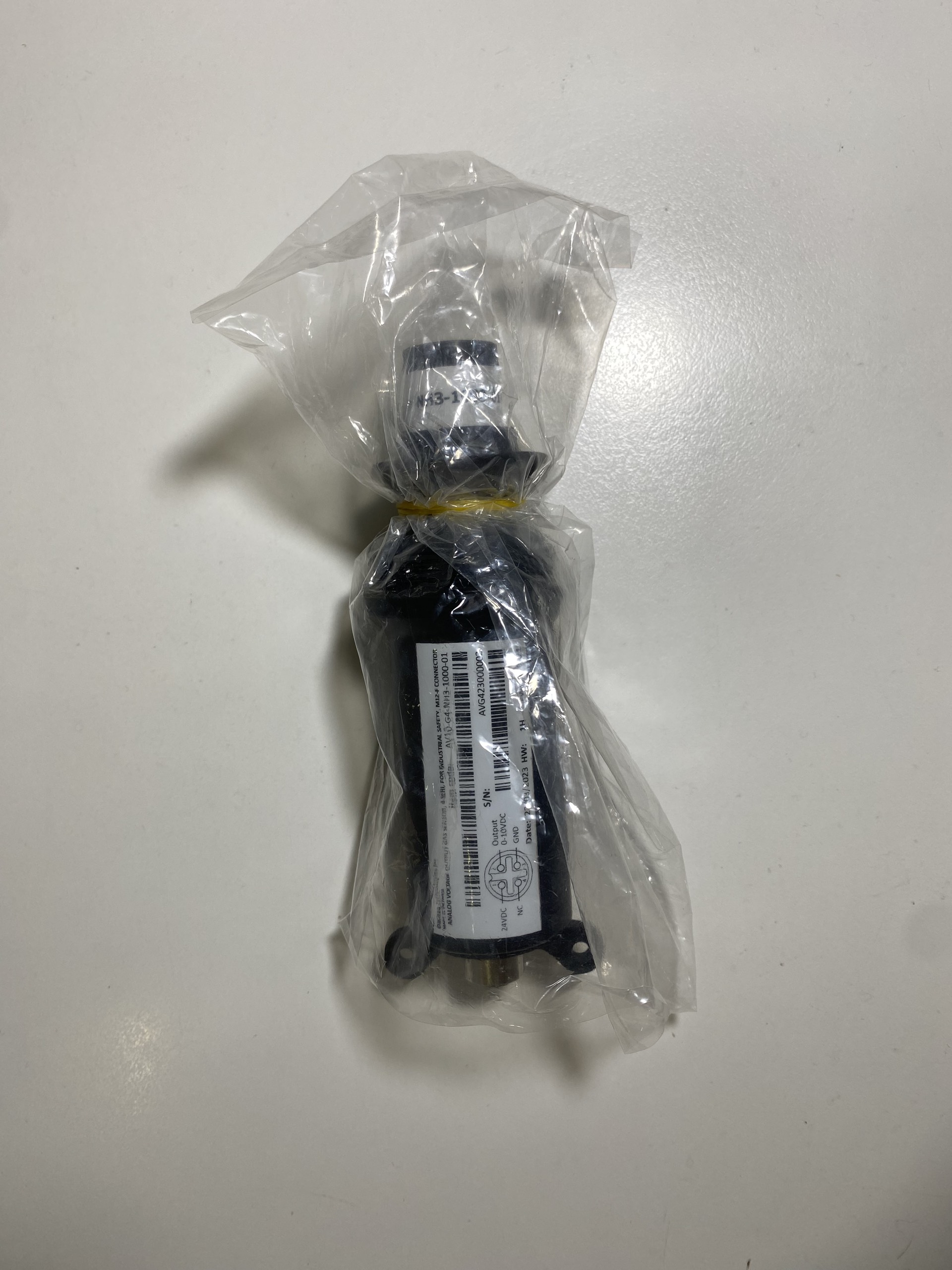
Bước 2. Dùng bao nylong và dây thun (dây chun) để bọc lại mô-đun cảm biến, chống nước và hơi ẩm thâm nhập vào đầu cảm biến, tránh rơi rớt và các tác động xung quanh.
|
|
Bước 3. Vệ sinh phần vỏ bảo vệ bằng nước và khí nén. Đảm bảo vỏ bảo vệ khô ráo hoàn toàn sau khi vệ sinh
|
Bước 4. Tháo bao nylon và lắp lại vỏ bảo vệ bằng cách vặn theo chiều kim đồng hồ.
|
END.
Daviteq Electrical Sensing Technologies
Daviteq AC 5A Current Transducer - Measurement Principle
1. Overview
Daviteq AC 5A current transducer is a transducer to convert the AC current from the Current Transformer (CT) to DULP digital output so that it can connect to any wireless transmitter of Daviteq.
It can connect to any brand of CT on the market.
2. Detail measurement principle
The AC current from CT will go thru a precision resistor to convert to voltage value in mV, then the electronics circuit will convert the mV signal to digital value via the DULP interface which is read by the wireless transmitter.
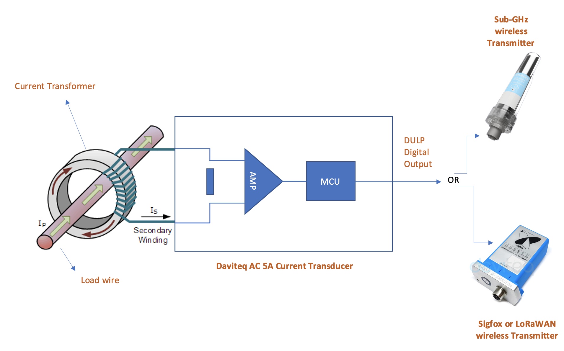
The Daviteq AC current transducer can connect to any Wireless transmitters manufactured by Daviteq which support DULP output.
* DULP: Digital Ultra-low Power

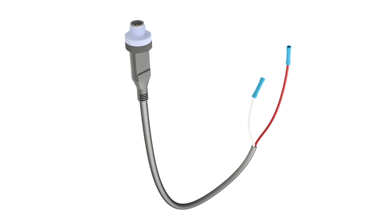
The AC current transducer connects to the Sub-GHz wireless transmitter WS433-AC
The transducer will output the actual current value of the secondary coil of the CT which has max 5A AC. To get the actual load current value, the user needs to configure the CT ratio in the wireless transmitter part.
For example:
* if the CT is 100/5 ==> the CT ratio must be 20;
* if the CT is 600/5 ==> the CT ratio must be 120;
3. Calibration of the Daviteq AC current transducer
The Daviteq AC current transducer is designed and manufactured with accuracy:
+/- 1% of Reading value and +/- 50 ppm of Reading per degree Celcius.
The user can do re-calibrating the transducer by using an AC current calibrator to generate the accurate AC current. The calibration will be done by changing the A & B factors on the wireless transmitter part. Please refer to the manual for the wireless transmitter to know how to change those A & B factors.
Note: the calibration of the AC current transducer must be carried with the wireless part (Sub-GHz or Sigfox or LoRaWAN) as the calibration factors A and B are stored on the memory of the wireless transmitter.
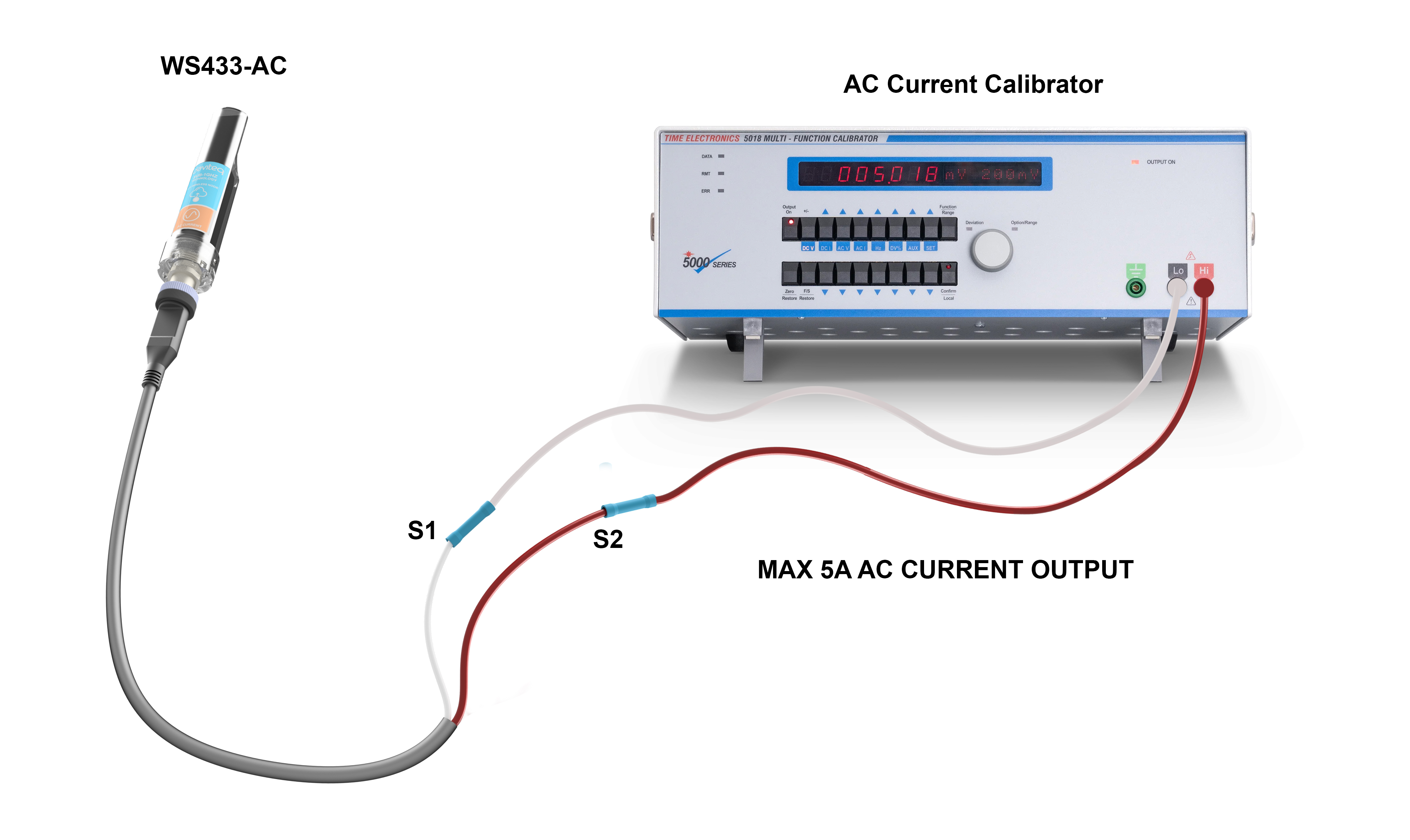
Diagram for re-calibrating the AC current transducer
4. Application notes for the Daviteq AC current transducer
The Daviteq AC current transducer together with a wireless transmitter to be used in the following cases:
- To measure the current load, power of the machine, equipment...to record the current load by time and detect when the load is over the threshold for protection, for safety.
- From the current load, the sensor can count the run time of the machine, equipment to deliver output how many hours of run, and how many hours of OFF, by setting the suitable threshold.
5. Installation Procedure
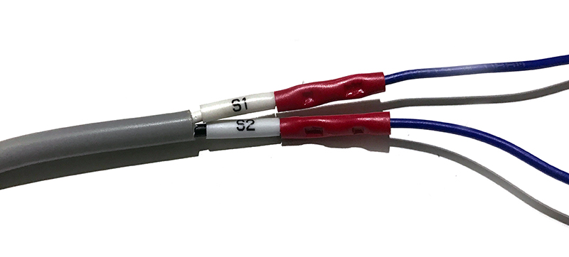
5.1 Connect the CT with the AC current transducer
Use the crimping tool to make the connection and protect the connection with a PVC heat shrink tube as below photos.

5.2 Connect the AC transducer to Wireless Transmitter
Connect the AC transducer to the wireless transmitter via the M12 connector.
Make sure the connection is firm and tight as in below photo.

6. Troubleshooting for the Daviteq AC current transducer
| No. | Phenomena | Reason | Solutions | |
| 1 | The measured value always shows Zero values. | 1.1 |
0.5A is the low cut value for this sensor. Therefore the actual load current (after multiplying the CT ratio) must be higher than 0.5A. |
Do nothing, it is the standard feature of the sensor. In case the measured load is too small, please make more loops on the CT, so that the measured current will be multiplied by the number of the loops. |
| 2 | The measured value is not as expected | 2.1 | The CT ratio is incorrect | Please check the actual ratio of CT and the configuration of CT in the wireless transmitter again. |
| 2.2 | Loosed connection of M12 connector of the transducer and wireless transmitter. | Check whether the M12 connector is firmly connected? | ||
| 2.3 | Wrong A and B values | Check the A & B in the configuration of the Wireless transmitter. Normally, A=1 and B=0. A & B can only be changed to other values when the transducer was re-calibrated by AC current calibrator. | ||
| 3 | HW_Error = 1 | 3.1 | Loosed connection of M12 connector of the transducer and wireless transmitter. | Check whether the M12 connector is firmly connected? |
| 3.2 | The transducer got a problem | Please consult the manufacturer for a warranty or replacement. |
7. Maintenance of the AC current transducer
There are no moving parts or consumed parts in the AC current transducer, therefore there is no need to do maintenance for the AC current transducer.
However, checking the grounding wire frequently is highly recommended.
8. Default configuration
This AC current transducer has the default configuration, however, those parameters cannot be changed. The user can change the configuration on the wireless transmitter so that the complete sensor (transducer + wireless) delivers the proper output value. Below are some configuration parameters that store in the flash memory of the wireless transmitter.
| Description | Unit | Default | Format | Property | Comment |
| CONSTANT_A | 1 | Float | R/W |
Constant a for scaling measured value |
|
| CONSTANT_B | 0 | Float | R/W |
Constant b for scaling measured value |
|
| HIGH_CUT | A | 1E+09 | Float | R/W |
High cut value for final value (after CT ratio) |
| LOW_CUT | A | 0.5 | Float | R/W |
Low cut value for final value (after CT ratio) |
| SENSOR_BOOT_TIME | mS | 1000 | Uint32 | R/W |
Boot time of sensor/input, in ms |
| CT | 40 | Float | R/W |
CT of current transformer |
END.
Daviteq Ultrasonic Level - Distance Measuring Technologies
Daviteq ULA Ultrasonic Level Sensor for Trash bin
1. Overview
Daviteq ULA ultrasonic level sensor is a dual-transducer ultrasonic sensor to measure the distance from the sensor surface to the object surface. Its design is dust and waterproof. Therefore the sensor can be installed in any trash bin for indoor and outdoor applications. With a very small blind zone (only 3 cm), it can be used for a small trash bin.
2. Detail measurement principle and its specification
It emits an ultrasonic pulse from the transmit transducer to the object, and the ultrasonic wave will reflect back to the receiving transducer. The micro-controller will measure the time difference between the sound wave from the transmitting transducer and the receiving reflected sound wave. From that, it calculates the distance by the following formula:
D = ( Time x V ) / 2
Where
D: Distance from the sensor to object surface
Time: the time difference between the wave from the transmitting transducer until receiving the reflected wave
V: velocity of ultrasonic wave in the environment.
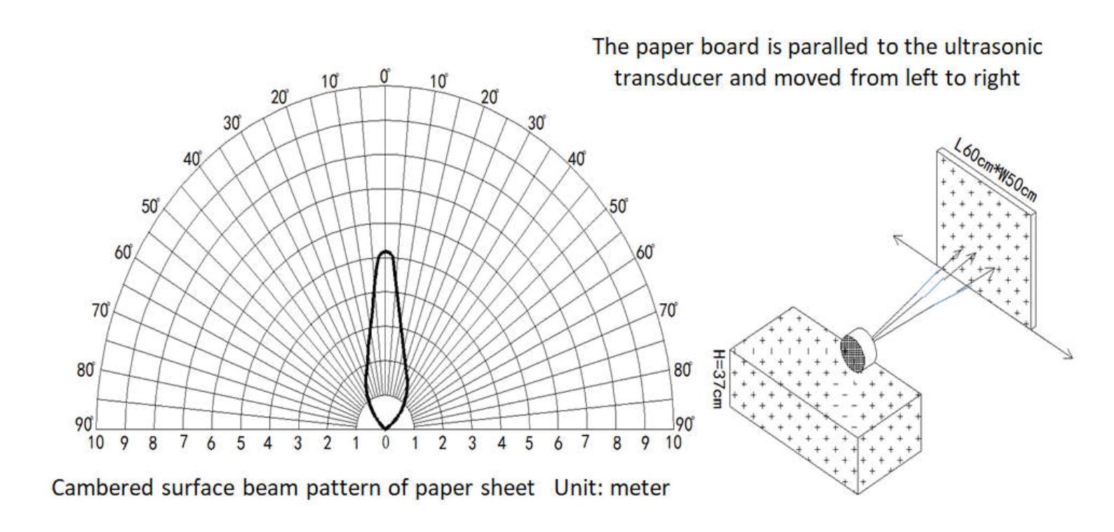
The effective detection range of the ULA sensor:
- The tested object is the white cylindrical tube, the material is PVC, height is 100cm, diameter is 75mm:
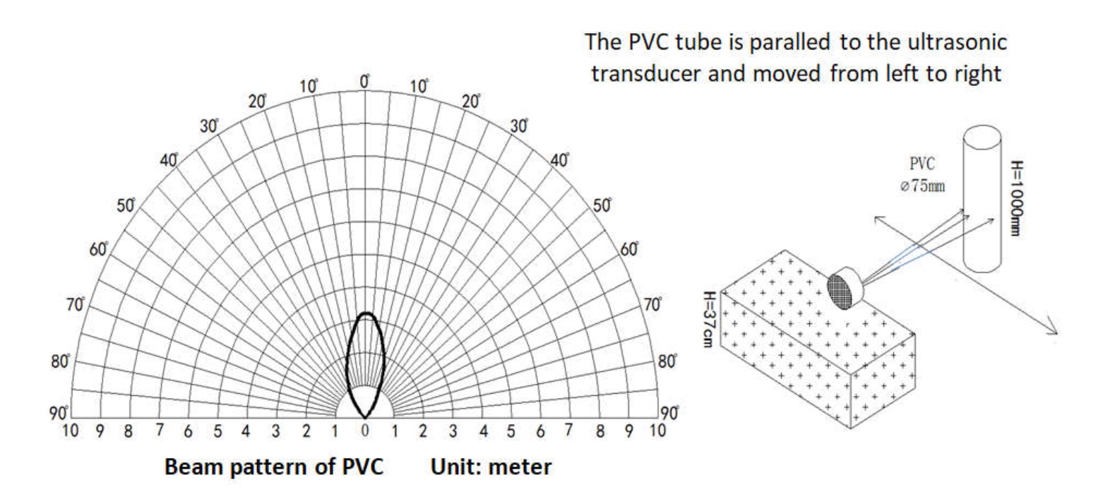
- The tested object is the carton board, placed in parallel with the sensor surface, carton board size is 60x50cm:
The smart firmware allows the sensor to filter the wrong echo signal from a rough surface in the trashbin so that it can deliver the accurate average distance or level value.
In addition, it also eliminates the wrong signal when the sensor is moving with the lid during opening (in a short time).
Note: The filter functions can be adjusted by changing the parameter Num_of_Samples. The higher value, the more effective filtering, the higher the energy consumption, and the shorter battery life.
ULA transducer specification
| Sensor technology | 40KHz Ultrasonic sensor |
| Blind zone | ~ 3 cm |
| Max detection range | ~ 450 cm (object is the carton board size 60x50cm, at 25 oC and 65% RH) |
| Working temperature/humidity | -15 .. + 60 oC / 0 - 99% RH (non-condensing) |
| Storage temperature/humidity | -25 .. + 80 oC / 0 - 99% RH (non-condensing) |
| Accuracy (at 25 oC, 65%RH) | +/- (1 cm + 0.5% of reading value) |
| Transducer material | Ceramic |
| Rating | IP68 (1m of water depth in 1h) |
3. Calibration of the Daviteq ULA ultrasonic level sensor
The Daviteq ULA ultrasonic level sensor measures the distance by taking the air speed of ultrasound in the ambient air. Therefore calibration is not required.
However, in most trash bin applications, customers need to get the level value (in ‰) instead of distance. To do so, please calculate the A & B value from the size of the trash bin as per the below instructions. DB: Dead band = 30 mm (This is a short range in front of the ultrasonic sensor can’t measure distances)
H: The height from sensor head to trashbin bottom (Inner surface)
D: The value of LEVEL_MM parameter. (Distance from sensor head to trash surface)
L : The value of LEVEL_THOUSANDTHS parameter. (Ranging 0 ‰ to 1000 ‰)
How to determine H value?
- Method 1:
Based on the design drawing of the trash bin or actual measurement - Method 2:
Read the sensor's measurement value when the trash bin is empty (L0). Then H = L0
Note: a1, b1 of sensor must be as default when use Method 2. (Default value a1=1, b1=0)
How to determine the new coefficients A and B?
The calibration formula is L = a x D + b.
Calibration at 2 points: L=0(‰) when D=H and L=1000(‰) when D=DB
Therefore, the new coefficients A and B must be configured according to the formula:
A = 1000 / (DB - H)
B = (1000 x H) / (H - DB)
After that, use the offline tool or downlink to configure A & B to the sensor.
4. Application notes for the Daviteq ULA ultrasonic level sensor
The Daviteq ULA ultrasonic level sensor together with a wireless transmitter to be used in the following cases:
- To measure the filling level of waste in the trash bin with a height size from 45 to 450 cm;
- To measure the distance from the sensor to an object such as a wall, a door opening...
5. Installation notes
- Make sure the installation environment does not emit gases that harm the transducer (ceramic materials) or the device housing (usually made from Polycarbonate);
- Make sure the measured distance must be within the detection range of the sensor;
- Do not place the transducer upward to the sky for outdoor application as the rain drops can cause malfunctioning;
- Make sure there is no impact on the transducer surface; it will cause the transducer to get damaged;
- Do not install the sensor in the closed compartment with solvent vapor or steam; it will cause the wrong measurement.
6. Troubleshooting for the ULA Ultrasonic Level Sensor
| No. | Phenomena | Reason | Solutions | |
| 1 | The distance value always shows 28-30mm | 1.1 |
The object is very close to the sensor, within the blind zone of the sensor. |
Do nothing, it is the standard feature of the sensor. The sensor can only measure the distance from 3 cm to 450 cm. |
| 1.2 | The transducer is covered by a thick layer of dust or particles. |
Clean the transducer surface with a soft detergent and clean water. |
||
| 2 | The distance value always shows 450-500 cm | 2.1 | The object is too far away from the sensor, it is out of the detection range of the sensor. | Make sure the measuring distance must be within the detection range of the sensor, 3-450 cm |
| 3 | The distance/level value fluctuates largely. | 3.1 | The object's surface (waste) is not flat and very rough. | Try to increase the parameter Num_of_samples to increase the filtering so that the sensor can deliver a stable average value. But it will cause the battery life to be shorter. We recommend the Num_of_sample is <= 50. |
| 3.2 | The sensor is mounted on the movable lid of the trash bin, and the moving speed of the lid is too long. Normally, the time of opening and closing should be less than 10s. |
Check the moving speed of the lid and try to increase its speed. If not, please try to increase the parameter Num_of_samples to increase the filtering so that the sensor can deliver a stable average value. But it will cause the battery life to be shorter. We recommend the Num_of_sample is <= 50. |
||
| 4 | The distance/level value is fixed at an abnormal value. | 4.1 | The sensor is mounted on the movable lid of the trash bin, and the lid is stuck and stays at the opening position all the time. |
Check the lid of the trash bin. |
| 5 | The level value is not accurate with the actual level of waste in the trash bin. | 5.1 | The transducer is covered by a thin layer of dust or particles. |
Clean the transducer surface with a soft detergent and clean water. |
| 5.2 | The A & B parameters are wrong or not written to the sensor yet. |
Check the calculation of A&B again and make sure they are written successfully to the sensor. |
||
| 6 | HW_Error = 1 | 6.1 | The lost connection between the transducer and the main PCB. | Open the sensor housing and check the internal wire and connector from the transducer to the wireless PCB. |
| 6.2 | The transducer got a problem. | Please consult the manufacturer for a warranty or replacement. |
7. Maintenance of the ULA Ultrasonic Level Sensor
- There are no moving parts or consumed parts in the ULA ultrasonic level sensor. Therefore there is no need to do maintenance.
- However, depending on the installation environment, the transducer must be checked and cleaned periodically for accurate measurement.
8. Default configuration
This ULA Ultrasonic level sensor has the default configuration. The user can change the configuration on the wireless transmitter so that the complete sensor (transducer + wireless) delivers the proper output value. Below are some configuration parameters that store in the flash memory of the wireless transmitter.
| Description | Unit | Default | Format | Property | Comment |
| CONSTANT_A | 1 | Float | R/W |
Constant a for scaling measured value |
|
| CONSTANT_B | 0 | Float | R/W |
Constant b for scaling measured value |
|
| HIGH_CUT | 1E+09 | Float | R/W |
High cut value for scaled value |
|
| LOW_CUT | -1E+09 | Float | R/W |
Low cut value for scaled value |
|
| SENSOR_BOOT_TIME | mS | 500 | Uint32 | R/W |
Boot time of sensor/input, in ms |
| NUM_OF_SAMPLES | 30 | Uint16 | R/W |
Number of samples for filtering function |
END.
Daviteq Air / Gas Flow Measurement Technologies
Thermal mass flow, Pitot tube, Orifice plate...
Daviteq AFD Air/Gas Flow Sensor
1. Overview
Daviteq AFD Air/Gas Flow Sensor is the flow probe that utilizes the Pitot tube measurement principle. This flow sensor is intended to use in the Duct Air of the HVAC system to measure the Air velocity and thus calculate the Air flow. The probe has various sizes to suit the pipe/duct size from 80mm to 2000mm in diameter.
2. Detail measurement principle and its specification
In the 18th century, French engineer Henri Pitot invented the Pitot tube, and in the mid-19th century, French scientist Henry Darcy modified it to its modern form. In the early 20th century, German aerodynamicist Ludwig Prandtl combined the static pressure measurement and Pitot tube into the Pitot-static tube, which is widely used today.
A schematic of a Pitot-static tube is shown in Figure 1. There are 2 openings in the tubes: one opening faces the flow directly to sense the stagnation pressure, and the other is perpendicular to the flow to measure the static pressure.
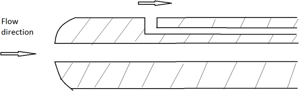
Figure 1. Schematic of a Pitot-static tube
The pressure differential is required to determine the flow speed, typically measured by pressure transducers. The below formula calculates the fluid velocity:
V = K x SQRT (DP)
Where:
- DP: Differential pressure measured by the sensor
- K: is the factor of the sensor design and the fluid type.
AFD flow sensor specification
| Sensor technology | Pitot tube flow sensor |
| Compatible gases | Air, Nitrogen, CO2, Oxygen. |
| Differential pressure range | +/- 2 in-H2O |
| Fluid velocity range | 0 - 28.5 m/s with Air at 25 oC |
| Max allowable static pressure | 270 in-H2O |
| Burst static pressure | 2800 in-H2O |
| Max allowable fluid velocity | 45 m/s (Air) at 25 oC |
| Drift | +/- 0.35m/s in 12 months (Air) |
| Accuracy | +/- 0.28 m/s in 0 .. + 50 oC (Air) |
| Output | DULP, via M12-M connector |
| Process connection | M34 x 1.5 male threads come with flange and gasket |
| Materials | Engineering plastic |
| Working Temperature | -20 .. + 85 oC |
| Working Humidity | 0 .. 95%RH |
| IP Rating | IP65 |
3. Calibration of the Daviteq AFD Air/Gas Flow Sensor
The Daviteq AFD Air/Gas Flow sensor is calibrated at the factory with Airflow. It is recommended the customer to re-calibrate the sensor every 12 months.
The local 3rd party can carry out the calibration, but the customer needs to order an accessory from the manufacturer for calibration.
In case of using the sensor with other gas (not with the Air), please configure the Density of Fluid (kg/m3) of the gas in the device. Please refer to the memory map in this link.
Notes:
* The calibration and configuration can only be done when the AFD probe is used with a Wireless transmitter like Sub-GHz (WS433-M12F-AFD) or LoRaWAN (WSLRW-M12F-AFD) or Sigfox (WSSFC-M12F-AFD
* After that, use the offline tool or downlink to configure A & B to the device.
4. Application notes for the Daviteq AFD Air/Gas Flow Sensor
The Daviteq AFD Air/Gas Flow Sensor together with a wireless transmitter to be used in the following cases:
- Air Duct of HVAC system;
- Hot air drying system;
- Cooling air system,...
It can be mounted on any shape of Duct or Pipe for sizes from 80mm to 2000mm.
5. Installation
.png)
Figure 2. Dimension drawing of AFD-0200
5.1 Mounting Direction
With Air/gas applications, the AFD flow sensor must be mounted as below figure. This ensures no fluid condensation inside the sensor for accurate and reliable measurement.
Notes:
* The Arrow on the probe must be in the same direction of fluid flow;
* Adjust the nozzle height so that the probe tip must be within the measurement zone (from 10% to 90% of the inner diameter of the pipe)
.jpeg)
Figure 3. Mounting direction of AFD flow sensor
D is the inner diameter of pipe
|
Figure 4. Wrong installation direction |
Figure 5. Not recommended installation direction |
.png)
.png)
5.2 Maximum misalignment
AFD flow sensor installation allows for a maximum misalignment of 3 degrees, as illustrated in the below figure. Misalignment beyond 3 degrees will cause errors in flow measurement.
.png)
Figure 6: Maximum misalignment
5.3 Up and Downstream Straight Pipe requirement
To ensure a homogeneous flow profile, it is necessary to mount the AFD flow sensor at a sufficient distance to narrow or bend of the pipe. The required upstream and downstream lengths for different types of obstacles are summarized in the following table:
|
Type of obstacle |
Min. upstream length |
Min. downstream length |
|
90° bend |
7 xD |
3x D |
|
2x90° bend in the same plane |
9xD |
3xD |
|
2x90° bend in perpendicular planes |
17 x D |
4xD |
|
concentric reducer |
7xD |
3xD |
|
concentric expander |
7xD |
3xD |
|
ball/gate valve, fully open |
24 x D |
4xD |
D: Inner pipe diameter
.png)
Figure 7. Maximum misalignment
1: upstream length; 2: downstream length; a: 90° bend; b: valve, open; c: 2x90° bend
5.4 Mounting Position
- The mounting position must be chosen such that access to the Device is always possible;
- Please take note of the specification of the flow sensor and wireless transmitter to ensure the complete set of devices is suitable for the process and environment of the installation.
5.5 Mounting the sensor AFD
5.5.1 Install the AFD sensor on the round pipe:
Follow these steps:
- Attach the nozzle with M34x1.5 female threads to the pipe. This work will be done by a professional mechanic;
- The Nozzle height is calculated so that the probe tip must be within the measurement zone;
- Cleaning the nozzle;
- Remove the neck out of the flange;
- Install the neck to the nozzle;
- Insert the probe into the flange neck and tighten the locking screw.
|
Figure 8. Install the probe into the Nozzle |
Figure 9. Fully installed probe on the round pipe |
.jpeg)
.jpeg)
5.5.2 Install the AFD sensor on the rectangular shape Duct:
Follow these steps:
- Drill a hole of 38mm diameter on the duct surface;
- Cleaning the hole;
- Place the gasket;
- Place the flange;
- Screwing the flange to the duct wall by using the self-tapping screws (supplied with the probe)
- Insert the probe into the flange neck and tighten the locking screw.
|
Figure 10. Install the probe into the rectangular duct |
Figure 11. The probe is completely installed on the rectangular duct |
.png)
.jpeg)
5.6 Adjust the orientation of the probe
- Unscrew the locking hex screw M4;
- Rotate the probe gently so that the arrow on the probe must be aligned with the pipe/duct direction. The misalignment must be not higher than 3 degrees;
- Tighten the locking screw again.
.png)
Figure 12. Adjust the orientation of the probe
5.7 Attach the Wireless Transmitter to the probe
.png)
Figure 13. Attach the wireless transmitter to the probe
6. Troubleshooting for the AFD Air/Gas Flow Sensor
| No. | Phenomena | Reason | Solutions | |
| 1 | The fluid velocity is very small or zero. | 1.1 | The probe orientation is wrong | Check and adjust the orientation again. |
| 1.2 | The connection between probe and wireless transmitter is not firm | Check the M12 connection again | ||
| 1.3 | Differential pressure sensor got a problem or Wireless transmitter got a problem. | Please consult the manufacturer for a warranty or replacement. | ||
| 2 | The probe or complete device vibrates during operation | 2.1 | Forget to tighten the screws during installation | Recheck the installation. |
| 3 | There is leakage of Air/Gas nearby the installation | 3.1 | The leakage could be from the O-ring, gasket, or sealing | Recheck the installation. |
| 4 | From system: HW_Error = 1 | 4.1 | The lost connection between the Probe and the wireless transmitter | Check the M12 connector and tighten it. |
| 4.2 | The Probe got a problem. | Please consult the manufacturer for a warranty or replacement. |
7. Maintenance of the AFD Air/Gas Flow Sensor
- There are no moving parts or consumed parts in the AFD Air/Gas Flow Sensor. Therefore there is no need to do maintenance.
- However, the pressure sensor in the probe will drift over time. We do recommend customer to re-calibrate it every 12 months. Please follow the calibration procedure in this link.
8. Default configuration
This AFD Air/Gas Flow Sensor has the default configuration. The user can change the configuration on the wireless transmitter so that the complete sensor (probe + wireless) delivers the proper output value. Below are some configuration parameters that store in the flash memory of the wireless transmitter.
| Description | Unit | Default | Format | Property | Comment |
| CONSTANT_A | 1 | Float | R/W |
Constant a for scaling pressure value (in Pa) |
|
| CONSTANT_B | 0 | Float | R/W |
Constant b for scaling pressure value (in Pa) |
|
| HIGH_CUT | 1E+09 | Float | R/W |
High cut value for scaled value |
|
| LOW_CUT | 0 | Float | R/W |
Low cut value for scaled value |
|
| SENSOR_BOOT_TIME | mS | 200 | Uint32 | R/W |
Boot time of sensor/input, in ms |
|
TEMPERATURE_OFFSET_X10 |
oC | 0 | int16 | R/W |
Offset adjustment for measured temperature value |
|
DENSITY_OF_FLUID |
kg/m3 | 1.225 | Float | R/W |
Fluid Density, default is Air |
END.
Daviteq Inertial Measurement Technologies
Daviteq V1A Vibration Sensor
1. Overview
Daviteq V1A Vibration Sensor is a vibration sensing module that utilizes the Piezo acceleration sensor to measure the vibration with a frequency of up to 10 kHz for condition monitoring and preventive maintenance applications.
The piezo-electric accelerometer is available in ranges ±25g or 50g and features a flat frequency response up to >10kHz. Its accelerometer feature a stable piezo-ceramic crystal in shear mode with low-power electronics, sealed in a fully hermetic package. The Piezo Electric technology V1A accelerometer has a proven track record for offering the reliable and long-term stable output required for condition monitoring applications. The accelerometer is designed and qualified for machine health monitoring and has superior Resolution, Dynamic Range, and Bandwidth to MEMS devices. Besides that, it can also measure the temperature at the mounting point.
With a built-in ultra-low power microprocessor, it can compute and deliver multiple parameters like velocity RMS/Peak, acceleration RMS/peak, displacement RMS/pk-pk, frequency, temperature, crest factor...
The V1A can be integrated into the wireless transmitter from Daviteq such as Sub-GHz WS433, LoRaWAN WSLRW, and Sigfox WSSFC. The connection can be via a 2m cable with an M12 connector or integrated type (WS433 only).
The V1A is also powered by the batteries in the wireless transmitter.
2. Detail measurement principle and its specification
V1A utilizes the single-axis Piezo acceleration sensor to detect the vibration of the object with vibration from 8Hz to 11 kHz.
A built-in high-accuracy solid-state temperature sensor allows the V1A to measure the object's surface temperature.
The microprocessor will capture the raw signal of acceleration and temperature values at a very high speed, up to 290 kHz. With this high-resolution raw signal, it performs various calculations to deliver the high accurate outputs like:
|
Velocity RMS (mm/s) |
Velocity Peak (mm/s) |
|
Acceleration RMS (m/s2) |
Acceleration Peak (m/s2) |
|
Displacement RMS (um) |
Displacement Peak-Peak (um) |
| Frequency of Highest amplitude vibration (Hz) | Surface Temperature (oC) |
These outputs will be sent to the wireless transmitter with a digital signal.
V1A specification
| Sensing technology | Hermetically Sealed, Piezo-Ceramic Crystal, Shear Mode |
|
Acceleration Range & Shock Limit (g) |
±25 or 50, 10,000 |
|
Frequency Response and Resonant (Hz) |
2 .. 10,000, > 30000 |
|
Non-Linearity, Transverse Sensitivity |
±2%FSO, < 5% |
|
Temperature measuring and operating |
-40°C .. +85°C, with accuracy: +/- 0.5 and resolution: 0.125 |
|
Sensor Material, rating, and mounting |
304SUS, IP67, M6 Screw |
|
Connector |
M12-M 5-pin (Coding A) with 2m cable or Integral type |
|
Parameter Measurement |
Acceleration RMS & Peak Velocity RMS & Peak Displacement RMS & Peak Frequency & Temperature |
|
Acceleration range and resolution |
+/- 25G, 6.1 mg |
|
Velocity range and resolution |
0 .. 50 mm/s, 0.1mm/s |
|
Displacement range and resolution |
+/- 5000 um, 1 um |
|
Frequency range and resolution |
2 .. 10,000 Hz, 1 Hz |
3. Calibration of the Daviteq V1A Vibration Sensor
The Daviteq V1A Vibration Sensor is calibrated at the factory. It is recommended the customer to re-calibrate the sensor every 12 months. Please contact us for calibration services.
Notes:
* The calibration and configuration can only be done when the V1A sensor is used with a Wireless transmitter like Sub-GHz (WS433-V1A) or LoRaWAN (WSLRW-V1A) or Sigfox (WSSFC-V1A).
* After that, use the offline tool or downlink to configure the A factor to the device.
4. Application notes for the Daviteq V1A Vibration Sensor
The Daviteq V1A Vibration Sensor together with a wireless transmitter to be used in the following cases:
- Measuring Single-axis vibration and/or surface temperature of Motor, Bearing, Pump, Fan, Gearbox, Rotary machine/equipment, or any object that has a vibration from 8 to 11,000 Hz.
.png)
Figure 1. The V1A sensor is mounted on a motor case.
5. Installation
5.1 Dimension Drawings
|
Figure 2. Dimension drawing of WS433-V1A-... |
Figure 3. Dimension drawing of V1A module which is used for WSLRW or WSSFC |
.png)
.png)
5.2 Mounting Position
Rule of thumb, the V1A will be installed at the place you want to measure the vibration and/or surface temperature.
Here are some recommendations for the installation of V1A on some typical equipment based on standard ISO 20816 (or ISO 10816).
|
Figure 4. Measuring points for pedestal bearings |
|
|
Figure 6. Measuring points for small electrical machines |
Figure 7. Measuring points for reciprocating engines close to the bearing locations |
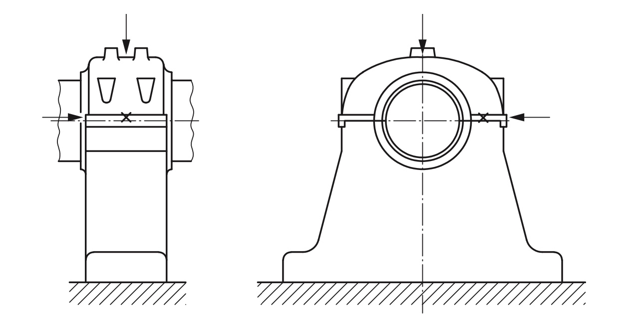
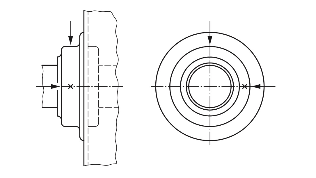
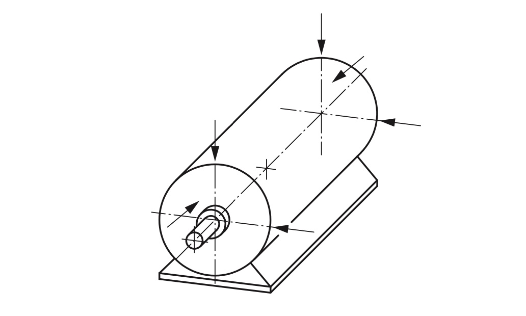
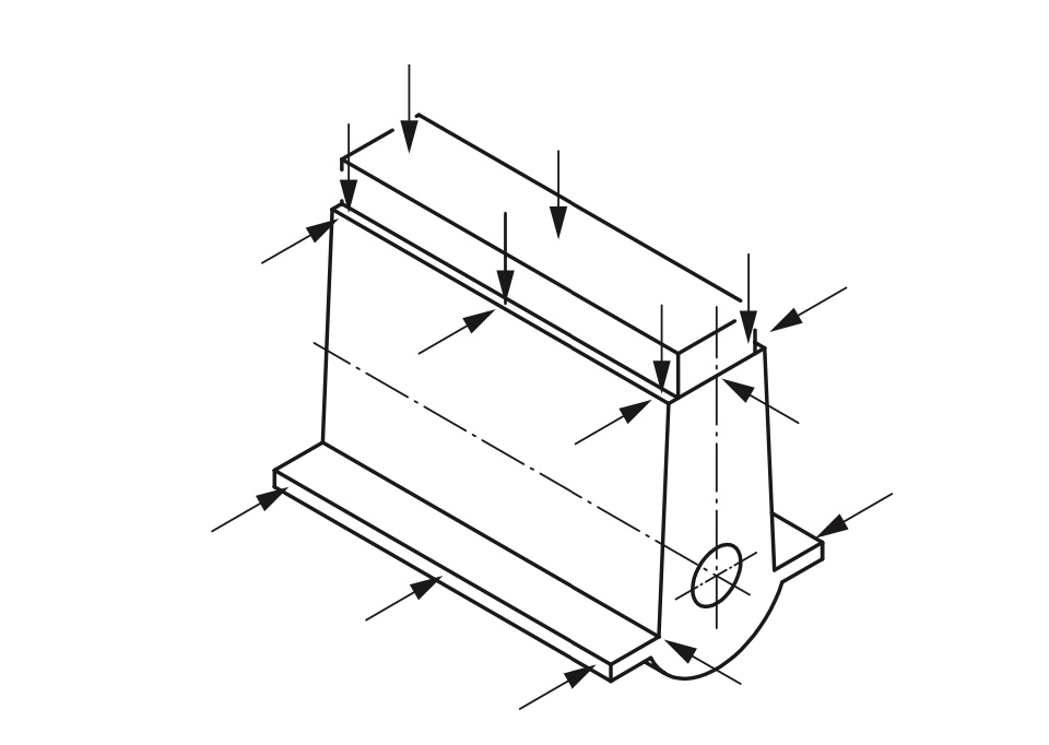
|
Figure 8. Measuring points for vertical machine sets |
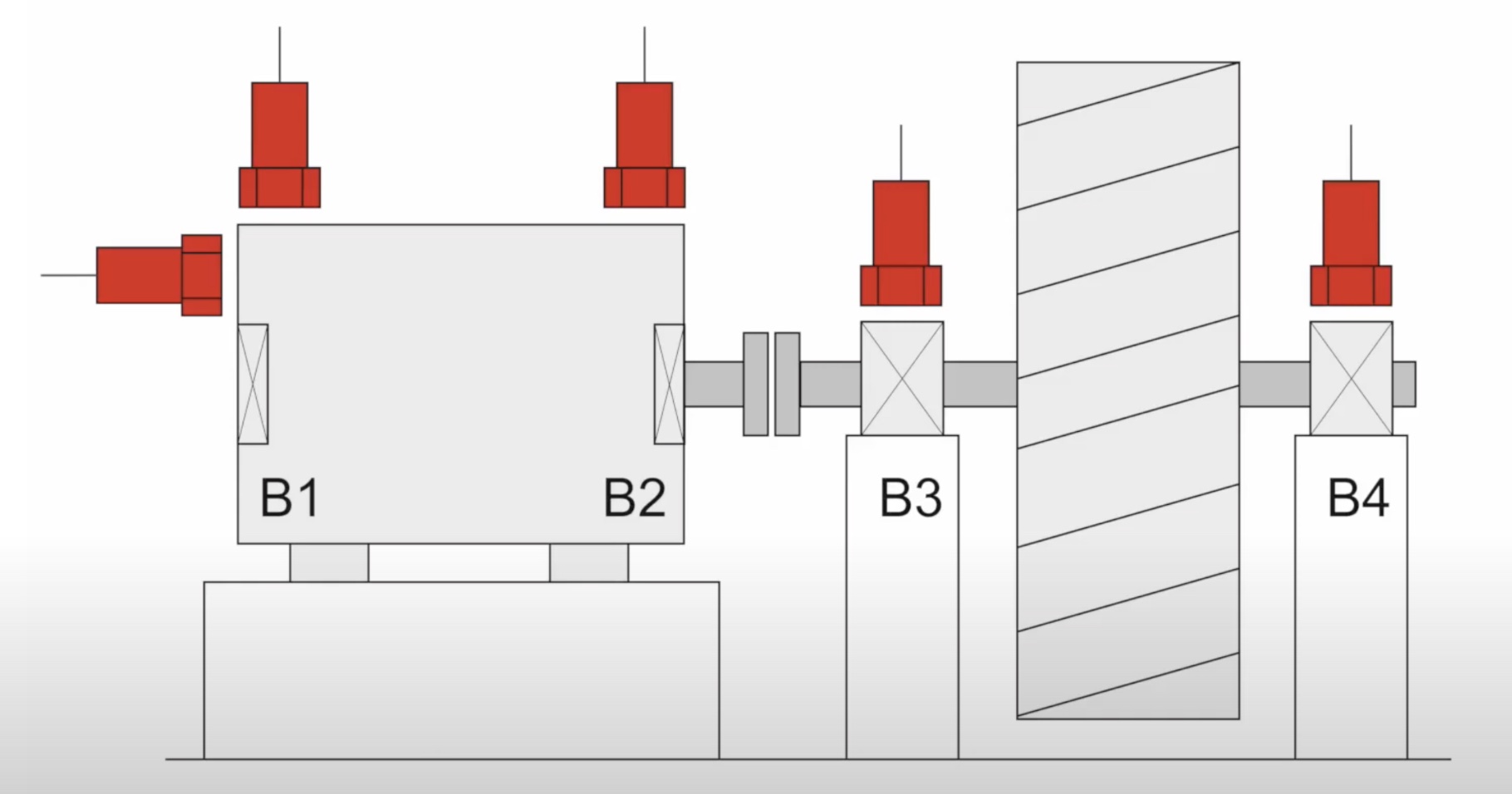
Figure 9. A pump system with 4 bearings and 5 positions of vibration monitoring |
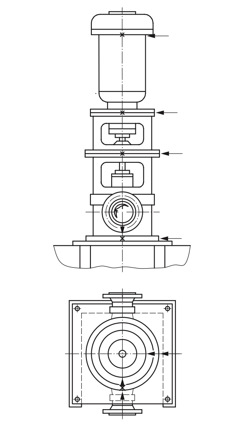
5.2 Mounting the sensor on the equipment's surface
The V1A sensor has the inner threads M6 and there is an M6 screw that comes with the sensor as standard.
There are 02 cases of mounting:
5.2.1 There are male threads or female threads at the place to mount the sensor:
- The V1A can be installed directly on the equipment's surface via an M6 screw or an adapter if the threads on the equipment are not M6. Please see the below figures.
|
Figure 10. There is inner threads M6 on the motor casing |
Figure 11. Mount the sensor on the M6 screw |
.png)
5.2.2 There are no male threads or female threads at the place to mount the sensor:
- If the drilling is allowed, please make a drilled hole and then tap the inner threads M6 on the surface of the equipment so that you can install the V1A directly on the surface of the equipment. Please see the below figure.
.png)
Figure 12. Drilling and tapping an inner threads M6 on motor casing
- if the drilling is NOT allowed, you can use the adhesive base (Item code: ACC-V1A-BASE-01) for mounting the V1A on the equipment. Please contact us for more information about this accessory.
Here are the steps to attach the adhesive base to the equipment's surface.
* Use sandpaper to remove the deposit or paint layer on the surface of the equipment;
* Clean the surface with alcohol;
* Mix 2-part of putty epoxy. Refer the instruction to mix 2-part of putty epoxy on the label of putty epoxy package.
* Apply the 2-part putty epoxy on the bottom surface of the base;
* Place the base on the surface;
* Use the leveling meter to level the surface of the base in 02 directions X and Y;
LEAVE IT COMPLETELY DRY AND HARDEN IN AT LEAST 24 HOURS
* Screw the M6 screw and install the sensor module.
|
Figure 13. Place the base with Epoxy on the equipment's surface |
Figure 14. Leveling it in the X direction |
|
Figure 15. Leveling it in the Y direction |
Figure 16. Leave it dry for 24 hours before installing the sensor |
.png)
.png)
.png)
.png)
Note: the adhesive base is for a flat surface only or a curved surface with a radius larger than 500mm.
5.3 Connect the M12 cable (for LoRaWAN of Sigfox Version)
Figure 13. Connect the M12 cable to the sensor module
6. Troubleshooting for the V1A Sensor
| No. | Phenomena | Reason | Solutions | |
| 1 |
The wireless transmitter is still running and sending data, however, all the measurement parameters are not updated with new values |
1.1 | The connection between the V1A sensor and the wireless transmitter is broken! |
For LoRaWAN or Sigfox version: check the M12 connector and the cable to see any abnormal or looseness.
For the WS433 version: check the looseness of connection between sensor and transmitter. |
| 1.2 | The battery is almost draining off. | Check the battery status and replace it when necessary. | ||
| 2 | The measured values are not as expected | 2.1 | The installation is not correct or not suitable for the sensor design. | Please recheck the installation. |
| 2.2 | The sensor is drifting. | Re-calibrate the sensor. Please contact us. | ||
| 3 | The reading values are very noisy even though there is no vibration. | 3.1 | The sensor V1A got a problem. | Please consult the manufacturer for a warranty or replacement. |
| 4 | From system: HW_Error = 1 | 4.1 | The lost connection between the sensor V1A and the wireless transmitter |
For LoRaWAN or Sigfox version: check the M12 connector and the cable to see any abnormal or looseness.
For the WS433 version: check the looseness of connection between sensor and transmitter. |
| 4.2 | The sensor V1A got a problem. | Please consult the manufacturer for a warranty or replacement. |
7. Maintenance of the V1A Vibration Sensor
- There are no moving parts or consumed parts in the V1A Vibration Sensor. Therefore there is no need to do maintenance.
- However, the sensor may be drifting over time. We do recommend customer to re-calibrate it every 12 months. Please follow the calibration procedure in this link.
8. Default configuration
The V1A Vibration Sensor has the default configuration. The user can change the configuration on the wireless transmitter so that the complete sensor (sensor + wireless) delivers the proper output values. Below are some configuration parameters that store in the flash memory of the wireless transmitter.
| Description | Unit | Default | Format | Property | Comment |
| CONSTANT_A | 1 | Float | R/W |
Constant a for calibrating the velocity RMS and thus calibrating the whole vibration sensor |
|
| ENB_DATAGRAM | 1 | Uint16 | R/W | bit0: enable datagram 0 bit1: enable datagram 1 bit2: enable datagram 2 |
|
|
TEMPERATURE_OFFSET_X10 |
oC | 0 | int16 | R/W |
Offset adjustment for measured temperature value |
END.
Daviteq AG Tilt Sensor
1. Overview
Daviteq AG Tilt Sensor is an Euler angle measurement sensor that utilizes the advanced MEMS acceleration sensor to measure the Euler angles in three directions. The acceleration sensor has high resolution and low noise allowing it to deliver very high resolution and low-temperature drift.
The AG can be integrated into the wireless transmitter from Daviteq such as Sub-GHz WS433, LoRaWAN WSLRW, and Sigfox WSSFC to build the complete Wireless Tilt Sensors.
The AG is also powered by the batteries in the wireless transmitter.
2. Detail measurement principle and its specification
AG utilizes the three-axis high accuracy MEMS acceleration sensor to calculate the static Euler angles of the object it is mounted on.
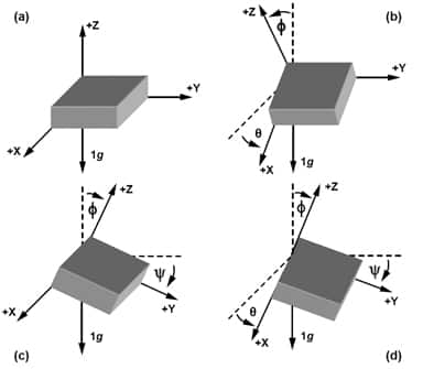
The microprocessor of the Wireless transmitter will capture the raw signal of 3-axis acceleration the calculate the tilt angle of X, Y, and Z. Here are the final output values of the device.
|
X Tilt value |
16-bit signed integer X_TILT_VALUE = X_TILT_VALUE_X10 / 10 Range: -90.0 to 90.0 |
|
Y Tilt value |
16-bit signed integer Y_TILT_VALUE = Y_TILT_VALUE_X10 / 10 Range: -90.0 to 90.0 |
|
Z Tilt value |
16-bit signed integer Z_TILT_VALUE = Z_TILT_VALUE_X10 / 10 Range: -90.0 to 90.0 |
AG Tilt Sensor's specification
| Sensing technology | MEMS acceleration |
| X/Y/Z tilt angle range | -90.0 to 90.0 degree |
|
Resolution |
0.01 o for AG-02 and 0.1 o for AG-01 |
| Repeatability | +/- 0.01 o for AG-02 and +/- 0.25 o for AG-01 |
| Within +/- 2.5 degrees of Tilt (for AG-02 version) | |
| Max Temperature drift | +/- 0.00065 o per oC |
| Max Non-linearity | +/- 0.0622 o |
| Total error in 20 oC deviation | +/- 0.075 o |
|
Parameter Measurement |
X tilt angle Y tilt angle Z tilt angle |
3. Calibration of the Daviteq AG Tilt Sensor
The Daviteq AG Tilt Sensor is calibrated at the factory. We highly recommend customers perform the offset adjustment on Software.
4. Application notes for the Daviteq AG Tilt Sensor
The Daviteq AG Tilt Sensor together with a wireless transmitter to be used to measure the Tilt angle of any object, for example:
- Tree;
- Bridge;
- Pole;
- Tower;
- Crane;
- Building...
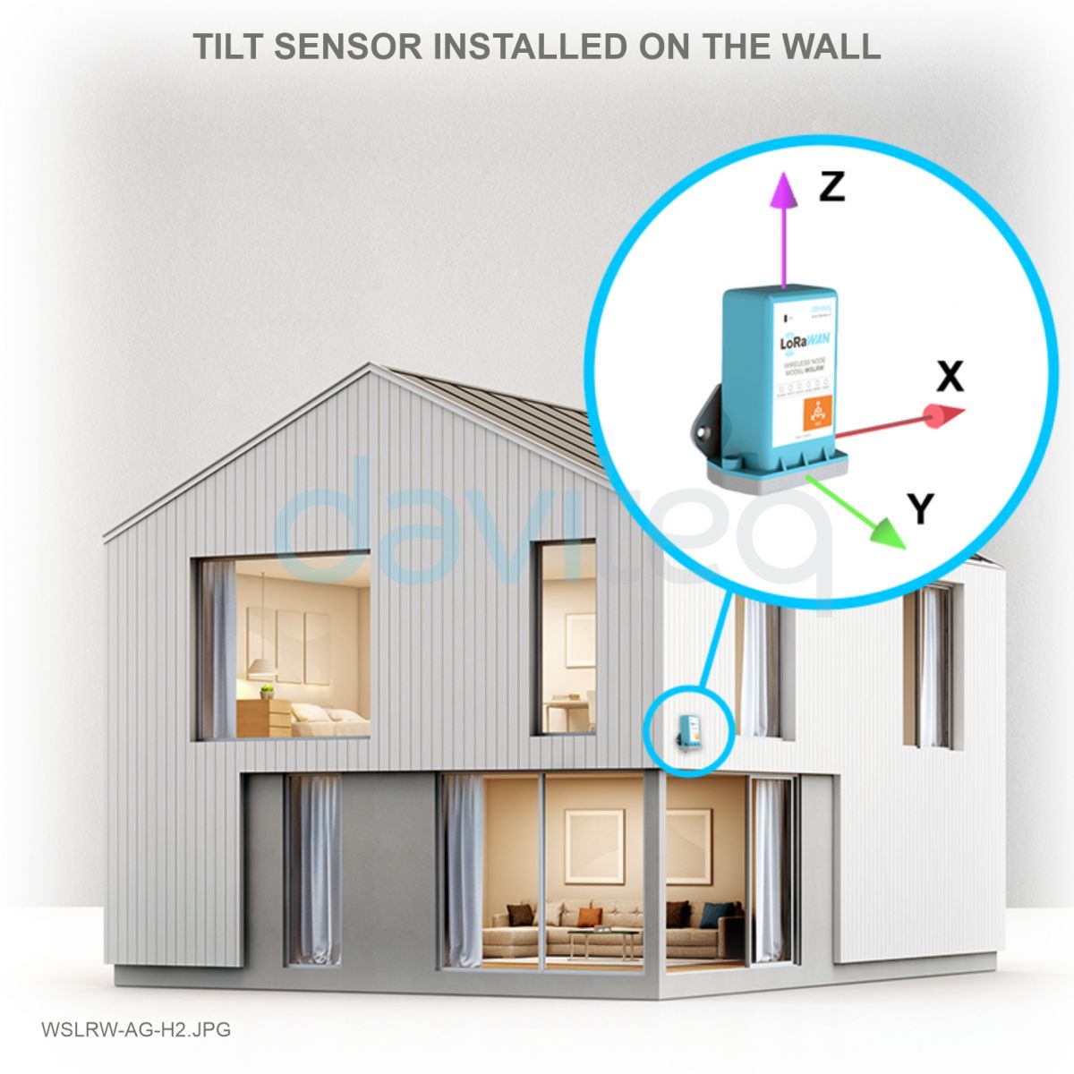 |
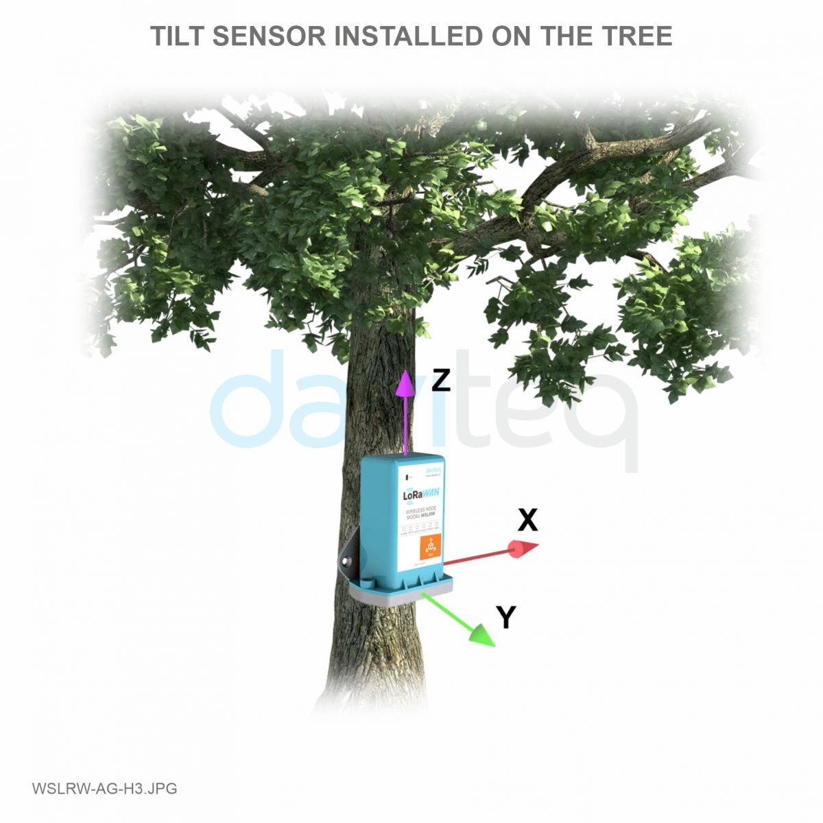 |
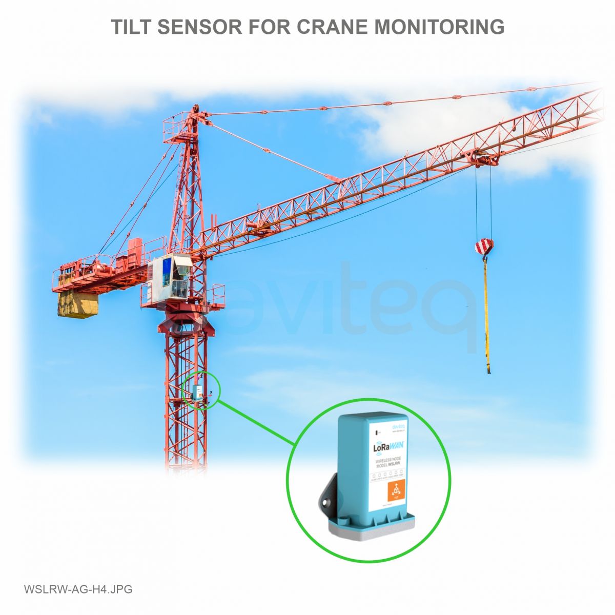 |
5. Installation
The AG sensor is built-in with the wireless transmitter. Therefore please refer to the installation procedure in the manual for the wireless transmitters.
6. Troubleshooting for the AG Tilt Sensor
| No. | Phenomena | Reason | Solutions | |
| 1 |
The wireless transmitter is still running and sending data, however, all the measurement parameters are not updated with new values |
1.1 | The connection between the AG tilt sensor and the wireless transmitter is broken! |
Please consult the manufacturer for a warranty or replacement. |
| 1.2 | The battery is almost draining off. | Check the battery status and replace it when necessary. | ||
| 2 | The measured values are not as expected | 2.1 | The installation direction is not correct. | Please recheck the installation. |
| 2.2 | The sensor is drifting. | Please consult the manufacturer for a warranty or replacement. | ||
| 3 | The reading values are very noisy even though the sensor is in a standstill position. | 3.1 | The sensor AG tilt sensor got a problem. | Please consult the manufacturer for a warranty or replacement. |
| 4 | From system: HW_Error = 1 | 4.1 | The lost connection between the sensor AG sensor and the wireless transmitter |
Please consult the manufacturer for a warranty or replacement. |
| 4.2 | The sensor AG sensor got a problem. | Please consult the manufacturer for a warranty or replacement. |
7. Maintenance of the AG Tilt Sensor
- There are no moving parts or consumed parts in the AG tilt Sensor. Therefore there is no need to do maintenance.
8. Default configuration
There is no configuration required for the AG tilt sensor. There is only configuration for the Wireless transmitter, please refer to the wireless transmitter's manual.
END.
Daviteq Pressure Measurement Technologies
Daviteq ULP Air/Gas Ultra-low Pressure Digital Sensor
1. Overview
Daviteq ULP Sensor is the digital, ultra-low pressure sensor offering state-of-the-art MEMS pressure transducer technology and CMOS mixed signal processing technology to produce a digital, fully conditioned, multi-order pressure and temperature compensated sensor. It is available in a gauge and a differential pressure configuration.
The total error band after autozero is less than 1%FS.
This ULP sensor module will be integrated with a transmitter module to give a suitable output like RS485 ModbusRTU, 4-20mA, 0-10V, Sub-GHz wireless, LoRaWAN, Sigfox, NBIoT...It is also powered by that transmitter.
Typical Applications of this Ultra-low Pressure Sensor:
-
Gas Flow Instrumentation
-
Air Flow Measurement
-
HVAC / VAV
-
Pressure Monitoring
- Negative Pressure Room Monitor
- Positive Pressure Room Monitor
- Filter Clogging Monitor
-
Safety Cabinets
2. Detail measurement principle and its specification
ULP can measure gauge pressure or differential pressure, please refer to below specification.
| Type | Min Pressure (Pa) | Max Pressure (Pa) | Total Error Band * (% FS) |
| ULP-G300 | 0 | +300 | +/- 1.0 |
| ULP-G600 | 0 | +600 | +/- 1.0 |
| ULP-D125 | -125 | +125 | +/- 1.25 |
| ULP-D250 | -250 | +250 | +/- 1.0 |
Common specification
| Operating Temperature | -20 .. + 85 oC |
| Compensation Temperature | -20 .. + 85 oC |
| Max allowable static pressure | 7 Kpa |
| Burst static pressure | 20 Kpa |
| Process connection | 6mm tube quick fittings |
| Electrical Connector | Integral PG9 connector or M12-M connector (for remote version) |
| Housing Material | Engineering Plastic |
| Process connection | 6mm tube quick fittings |
| Working Humidity | 0 .. 100%RH |
| IP Rating | IP67 |
3. Calibration of the Daviteq AFD Air/Gas Flow Sensor
The Daviteq ULP pressure sensor is calibrated at the factory.
The customer is recommended to re-calibrate the sensor every 12 months by the Ultra-low pressure calibrator or by a 3rd-party.
Notes:
* The calibration and configuration can only be done when the ULP module is used with a transmitter like Sub-GHz (WS433-M12F-AFD) or LoRaWAN (WSLRW-M12F-AFD) or Sigfox (WSSFC-M12F-AFD, or ModbusRTU
* After that, use the offline tool or downlink to configure A & B to the device.
4. Application notes for the Daviteq ULP Ultra-low Pressure Sensor
The Daviteq ULP Ultra-low Pressure Sensor together with a transmitter to be used in the following cases:
-
Gas Flow Instrumentation
-
Air Flow Measurement
-
HVAC / VAV
-
Pressure Monitoring
- Negative Pressure Room Monitor
- Positive Pressure Room Monitor
- Filter Clogging Monitor
-
Safety Cabinets
5. Installation
5.1 Mounting Direction
The sensor can be mounted in any direction. After fixing, please perform the zero calibration to get a correct reading.
5.2 Connect tubing
Use the 6mm OD plastic tubes to connect to the H and L pressure ports of the sensor.
5.3 Mounting Position
- The mounting position must be chosen such that access to the Device is always possible;
- Please take note of the specification of the ULP sensor and its transmitter to ensure the complete set of devices is suitable for the process and environment of the installation.
6. Troubleshooting for the ULP Sensor
| No. | Phenomena | Reason | Solutions | |
| 1 | The pressure value is always very small or zero. | 1.1 | The tubes are bending or breaking | Check the tubes and connection |
| 1.2 | The connection between the sensor and transmitter is not firm | Check the electrical connection of the sensor module | ||
| 1.3 | The pressure sensor got a problem or the transmitter got a problem. | Please consult the manufacturer for a warranty or replacement. | ||
| 2 | From system: HW_Error = 1 | 2.1 | The lost connection between the sensor and the transmitter | Check the electrical connection of the sensor module |
| 2.2 | The sensor module got a problem. | Please consult the manufacturer for a warranty or replacement. |
7. Maintenance of the ULP Sensor
- There are no moving parts or consumed parts in the ULP Sensor. Therefore there is no need to do maintenance.
- However, the pressure sensor will drift over time. We do recommend customer to re-calibrate it every 12 months.
8. Default configuration
This ULP Sensor has the default configuration. The user can change the configuration on the transmitter so that the complete device (sensor + transmitter) delivers the proper output values. Below are some configuration parameters stored in the transmitter's flash memory.
| Description | Unit | Default | Format | Property | Comment |
| CONSTANT_A | 1 | Float | R/W |
Constant a for scaling pressure value (in Pa) |
|
| CONSTANT_B | 0 | Float | R/W |
Constant b for scaling pressure value (in Pa) |
|
| HIGH_CUT | 1E+09 | Float | R/W |
High cut value for scaled value |
|
| LOW_CUT | 0 | Float | R/W |
Low cut value for scaled value |
|
| SENSOR_BOOT_TIME | mS | 200 | Uint32 | R/W |
Boot time of sensor/input, in ms |
|
TEMPERATURE_OFFSET_X10 |
oC | 0 | int16 | R/W |
Offset adjustment for measured temperature value |
END.
Instructions for Grounding of Pressure Sensor
| DEC-2022 |
CONNECTING GND FOR SENSOR
Step 1: Open the blue housing of the sensor

Step 2: Locate the GND point on the PCB (same GND point of Battery);
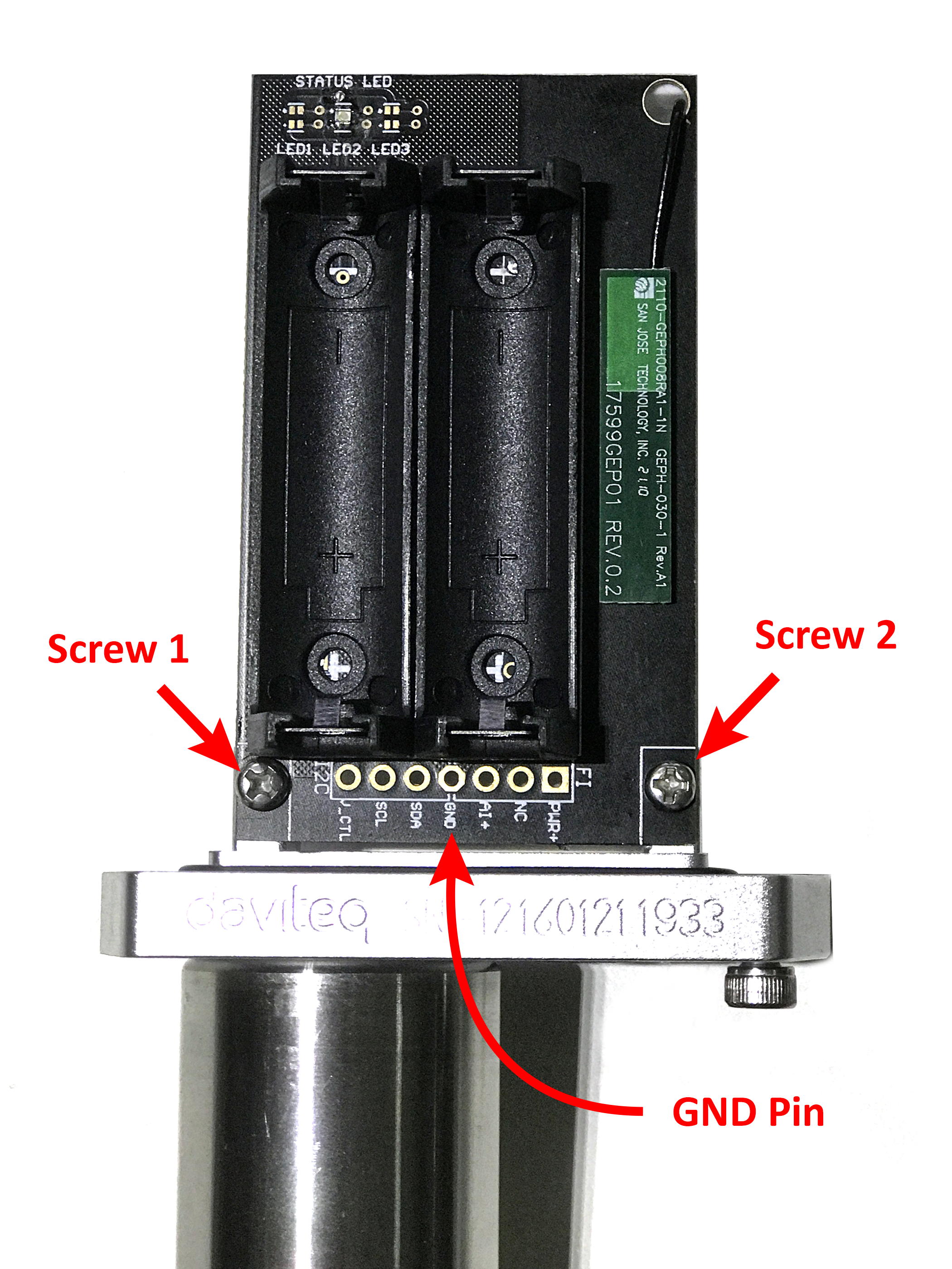
Step 3: Solder a wire to this GND point; the other end of the wire will be screwed to 1 of 2 screws on the aluminum base;
.jpeg)
Step 4: Outside of the aluminum base there is another screw → make a wire connection from this screw to the body of pressure sensor (stainless steel cylindrical body) → Use a hose clamp or stainless steel pipe bracket to lock the connection between the wire and the housing.
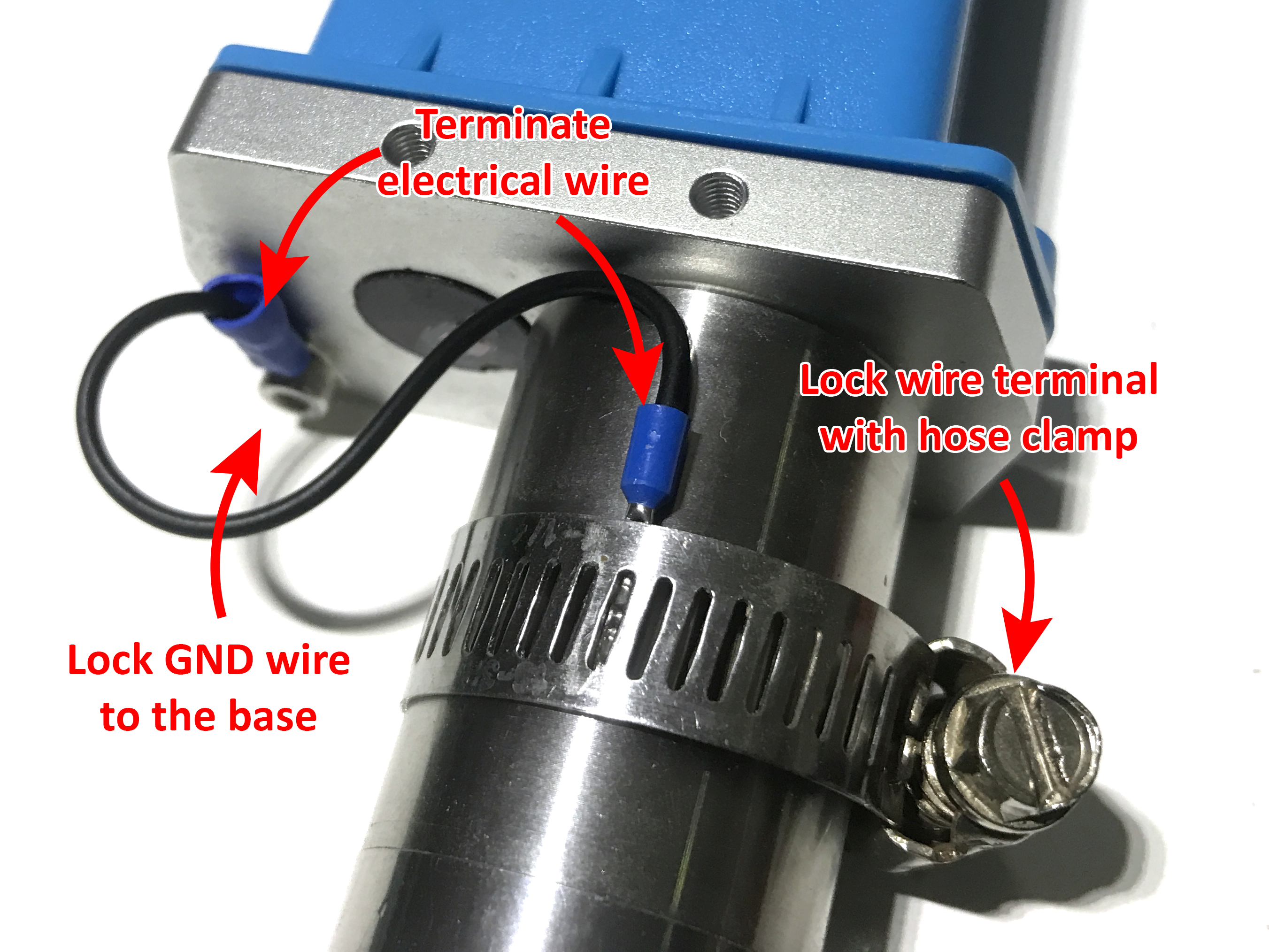
Support contacts
Manufacturer
![]()
Daviteq Technologies Inc
No.11 Street 2G, Nam Hung Vuong Res., An Lac Ward, Binh Tan Dist., Ho Chi Minh City, Vietnam.
Tel: +84-28-6268.2523/4 (ext.122)
Email: info@daviteq.com | www.daviteq.com
Daviteq Soil Measurement Sensors
Daviteq SMT Soil Moisture and NPK Sensor - Measurement Principle
1. Introduction
1.1 Overview
Daviteq SMT is a Soil Moisture and NPK sensor that can simultaneously monitor soil temperature, humidity, conductivity, salinity, nitrogen, phosphorus, and potassium values in soil. By measuring the dielectric constant of the soil, it can directly and stably reflect the true moisture content of various soils. It can measure the volume percentage of soil moisture, which is a soil moisture measurement method that meets the current international standards. By measuring the electrical conductivity of the soil, the salinity reflects the salinity of the soil in time, and by measuring the nitrogen, phosphorus, and potassium content of the soil, it reflects the nutrient status of the soil in time, providing data basis for scientific planting.
It has ultra-low power consumption to allow it to be integrated with Wireless Devices such as Sub-GHz transmitter, Sigfox transmitter, LoRaWAN transmitter, RS485 output transmitters, etc.
1.2 Highlight Features
-
- The seven parameters of soil water content, electrical conductivity, salinity, temperature and nitrogen, phosphorus, and potassium are combined into one;
- Low threshold, few steps, fast measurement, no reagents, unlimited detection times;
- It can also be used for the conductivity of water and fertilizer-integrated solutions, and other nutrient solutions and substrates;
- The electrode is made of specially processed alloy material, which can withstand strong external impact and is not easy to damage;
- Completely sealed, and resistant to acid and alkali corrosion can be buried in soil or directly into the water for long-term measuring;
- High precision, fast response, good interchangeability, probe plug-in design to ensure accurate measurement and reliable performance;
- Typical Applications of Daviteq SMT Soil sensor.
1.3 Typical Applications of Daviteq SMT Soil Sensor
The SMT sensor is suitable for soil moisture monitoring, scientific experiments, water-saving irrigation, greenhouses, flowers and vegetables, grassland pastures, soil rapid testing, plant cultivation, sewage treatment, and precision agriculture...
1.4 Specification
| Sensor Types | SMT-07 | SMT-01 |
| Sensor technology | FDR Capacitance | FDR Capacitance |
| Measurement Parameters |
Soil moisture, Temperature, EC, Salinity, and NPK |
Soil moisture, and Temperature |
| Temperature measuring range / Resolution / Accuracy |
-40° C~80° C / 0.1 / +/- 0.5 |
-40° C~80° C / 0.1 / +/- 0.5 |
| Soil Moisture range / Resolution / Accuracy |
0 - 100% vol. / 0.1 / 0-50%: ±2%; 53%-100%: ±3% |
0 - 100% vol. / 0.1 / 0-50%: ±2%; 53%-100%: ±3% |
| Electrical Conductivity range / Resolution / Accuracy | 0 - 20.000 us/cm / 1 / +/- 3% of reading | N/A |
| Salinity range / Resolution / Accuracy | 0 - 10.000 ppm / 1 / +/- 3% of reading | N/A |
| N,P,K range / Resolution / Accuracy | 1 - 1999 mg/kg / 1 / +/- 2% of Full scale | N/A |
| Response Time | < 15s | < 15s |
|
Conductivity temperature compensation |
Built-in compensation in range 0 - 50 oC | N/A |
| Working temperature | -40 .. + 80 oC | -40 .. + 80 oC |
| Working humidity | 0 - 100 %RH | 0 - 100 %RH |
| Ingress Protection | IP68 | IP68 |
| Housing materials | ABS plastic with potting | ABS plastic with potting |
| Electrode material | 316SS | 316SS |
2. Principle of operation
FDR (Frequency Domain Reflectometry) type sensor is mainly composed of a parallel arrangement of the metal bar as a capacitor. In which the soil acts as a dielectric, the capacitor and oscillator are composed of a high-frequency tuning circuit. The electromagnetic wave through the coaxial cable arrives at the probe, and the resonance frequency is detected by the frequency sweep circuit. The dielectric constant of the soil can be measured so that the soil water content is obtained. The dielectric constant of water is 80 F m-1 and the soil solid dielectric constant is 2~5 F m-1; the dielectric constant of water is much bigger than soil. Therefore, the dielectric constant of soil is mainly affected by soil moisture content. Moisture content increases, the soil dielectric constant will increase accordingly, and the frequency of the electromagnetic wave propagation will change.
Besides the moisture content, the sensor also can measure the electrical conductivity of the soil and calculate the other parameters like Salinity, N, P, and K.
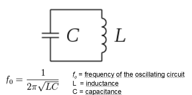
Operating principle for soil water content measurements.
Sensor and soil act as oscillating circuits with an inductor and capacitor.
3. Calibration of the Daviteq SMT Soil Sensor
The Daviteq SMT Soil Sensor is pre-calibrated with standard soil before shipping. Users can make further adjustments/calibrations in their software or reading device to meet higher accuracy for their specific soil.
4. Application notes for the Daviteq SMT Soil Sensor
- FDR sensors need to have good contact with the medium they measure with no air gaps;
- Since the electrode directly measures the conductivity of the soluble salt ions in the soil, the soil volumetric water content must be higher than about 20% when the soluble ions in the soil can accurately reflect the conductivity of the soil. In the long-term observation, the measured value after irrigation or rainfall is closer to the true level. If you are performing a quick test, you can water the soil to be tested first, and perform the measurement after the water is fully penetrated;
- The sensor should be protected from severe vibration and impact, let alone knocked with hard objects;
- Because the sensor has a black housing, the sensor will heat up sharply (up to 50°C) under strong sunlight. In order to prevent excessive temperature from affecting the temperature measurement of the sensor, please pay attention to shading and protection when using it in the field.
5. Installation notes
General Notes:
* All the metal electrodes must be inserted into the soil during measurement;
* Avoid direct sunlight on the sensor, which will cause excessive temperature;
* Do not bend the metal electrodes violently, do not pull the sensor lead wire with force, and do not beat or violently impact the sensor;
* The protection grade of the sensor is IP68, which can soak the sensor in water;
5.1 Soil Surface Measurement:
- Clean the soil surface by removing the debris, and vegetation...
- Insert the electrodes completely in the soil, as in the below picture;
- If you measure on a hard surface, you should drill a hole first (the hole diameter should be smaller than the probe diameter), then insert it into the soil and compact the soil before measuring;
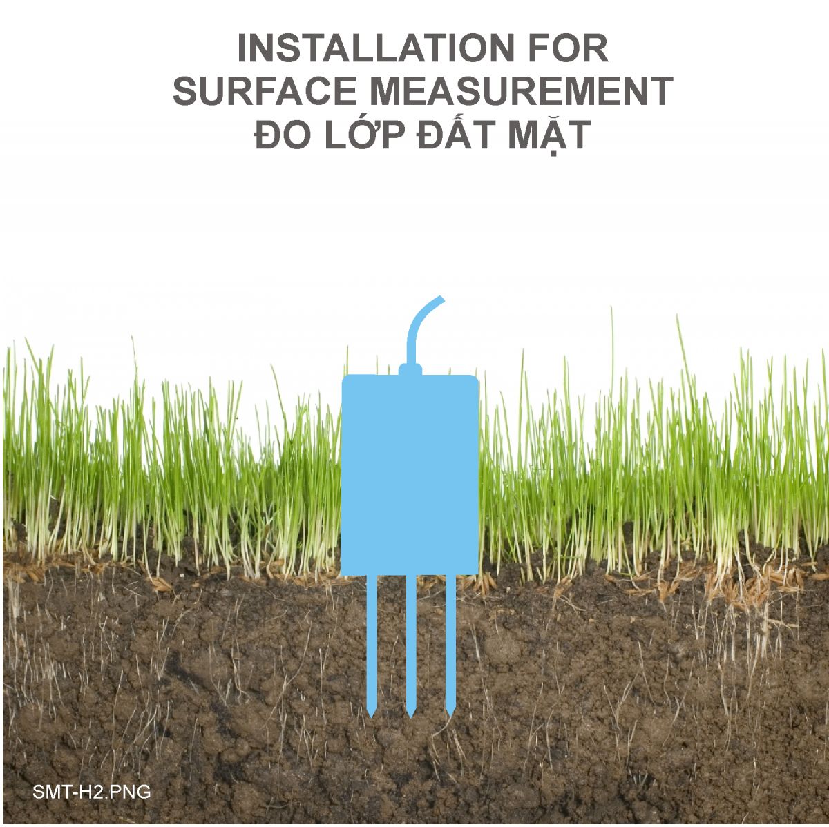
5.2 Multi-layer Measurement
- Make a soil profile in the vertical direction, slightly deeper than the installation depth of the bottommost sensor, between 20cm and 50cm in diameter;
- Insert the probes horizontally at different layers of soil;
- After the installation is completed, the excavated soil is backfilled in order, layered, and compacted, and horizontal installation is guaranteed.
| 3-layer measurement | 6-layer measurement |
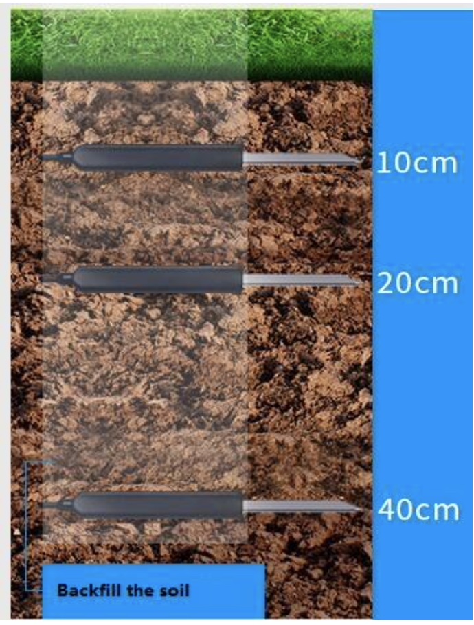 |
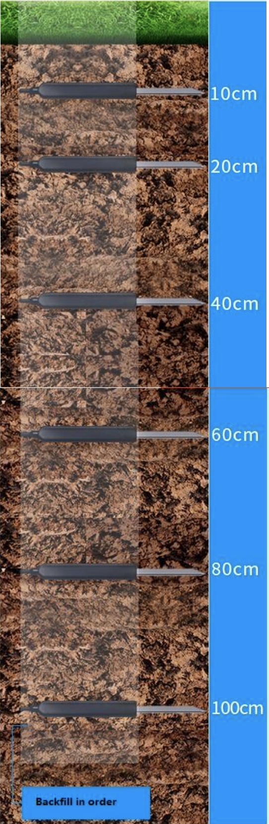 |
6. Troubleshooting for the Daviteq SMT Soil Sensor
| No. | Phenomena | Reason | Solutions | |
| 1 | The measured value is not within the expected value. | 1.1 | The soil is not compact. | Make sure the soil is compact and there are no air gaps between the soil and electrodes |
| 1.2 | The soil is special | Calibrate or adjust the reading values on software or reading device based on the actual values of that soil. | ||
| 1.3 | The sensor was spoiled. | Please consult the manufacturer for a warranty or replacement. | ||
| 2 | The measured values of EC, Salinity, and NPK are always zero or near zero. | 2.1 | The soil moisture is too low, less than 20%. Therefore the circuit cannot measure the electrical conductivity of the soil | Watering the soil and/or keep holding the last values of EC, Salinity, and NPK in the Software system or reading device. |
| 2.2 | The sensor was spoiled. | Please consult the manufacturer for a warranty or replacement. | ||
| 3 | HW_Error = 1 | 3.1 | Loosed connection of sensor probe and wireless transmitter. | Check the sensor cable and connector. |
| 3.2 | The sensor probe got a problem. | Please consult the manufacturer for a warranty or replacement. |
7. Maintenance of the Daviteq SMT Soil Sensor
The SMT soil sensor is a maintenance-free sensor.
8. Default configuration
This SMT soil sensor has the default configuration, however, those parameters can be changed. The user can change the configuration on the wireless transmitter so that the complete sensor (transducer + wireless) delivers the proper output value. Below are some configuration parameters that store in the flash memory of the wireless transmitter.
8.1 For SMT-07
| Description | Unit | Default | Format | Property | Comment |
8.2 For SMT-01
| Description | Unit | Default | Format | Property | Comment |
END.