GAS MEASUREMENT LIST
- ELECTRO-CHEMICAL GAS SENSORS
- DAVITEQ ETHYLENE C2H4 GAS SENSOR, 1500 PPM, SERI-4
- DAVITEQ CARBON MONOXIDE CO GAS SENSOR, 200 PPM, SERI-4
- DAVITEQ HYDRO SULFIDE H2S GAS SENSOR, 50 PPM, SERI-4
- DAVITEQ AMMONIA NH3 GAS SENSOR, 100 PPM, SERI-4
- DAVITEQ CHLORINE Cl2 GAS SENSOR, 20 PPM, SERI-4
- DAVITEQ NITROGEN DIOXIDE NO2 GAS SENSOR, 20 PPM, SERI-4
- DAVITEQ OXYGEN O2 GAS SENSOR FOR HIGH HUMIDITY 0-30%, SERI-4
- DAVITEQ OXYGEN O2 GAS SENSOR 0-30%, SERI-4
- DAVITEQ TRACE OXYGEN O2 GAS SENSOR 0-1%, SERI-4
- Daviteq Electro-Chemical Gas Sensor
- DAVITEQ FORMALDEHYDE GAS SENSOR CH2O, 10 PPM, SERI-4
- PID GAS SENSORS
- NDIR GAS SENSOR
ELECTRO-CHEMICAL GAS SENSORS
DAVITEQ ETHYLENE C2H4 GAS SENSOR, 1500 PPM, SERI-4
SENSOR SPECIFICATION
| MEASURING SPECIFICATION | |
| Sensor type | Seri-4 electro-chemical gas sensor |
| Nominal range | 0-1500 ppm |
| Maximum overload | 3000 ppm |
| Resolution | 4 ppm |
| T80 response time | < 60 s |
|
Typical Baseline Range (pure air, 20°C) |
-10 ppm .. + 35 ppm |
| Repeatability | < 2% of reading |
| Accuracy | +/- 5% of reading |
| Zero Stability | 0 .. 35ppm in pure Air, 20oC |
| Temperature compensation | Yes |
| WORKING CONDITIONS | |
| Relative humidity range |
15 % to 90 % RH non-condensing |
| Temperature range |
-40 °C to 50 °C |
| Pressure range |
Atmospheric ± 10% |
| SENSOR LIFETIME | |
|
Expected Operation Life |
2 years in the air |
|
Expected Long Term Output Drift in air |
< 5 % of reading loss per month |
CROSS SENSITIVITY DATA
|
Interfering Gas |
Cross-Sens. [%] |
|
CO |
< 60 |
DAVITEQ CARBON MONOXIDE CO GAS SENSOR, 200 PPM, SERI-4
SENSOR SPECIFICATION
| MEASURING SPECIFICATION | |
| Sensor type | Daviteq Seri-4 electro-chemical gas sensor |
| Nominal range | 0-200 ppm |
| Maximum overload | 500 ppm |
| Filter | Inboard filter to remove acidic gases |
| Resolution | 0.1 ppm |
| T90 response time | < 35 s |
|
Typical Baseline Range (pure air, 20°C) |
-0.5 ppm .. + 0.7 ppm |
| Repeatability | < 2% of reading |
| Accuracy | +/- 5% of reading |
| Zero Stability | 0 .. 0.5 ppm in pure Air, 20oC |
| Temperature compensation | Yes |
| WORKING CONDITIONS | |
| Relative humidity range |
15 % to 90 % RH non-condensing |
| Temperature range |
-40 °C to 50 °C |
| Pressure range |
Atmospheric ± 10% |
| SENSOR LIFETIME | |
|
Expected Operation Life |
3 years in the air |
|
Expected Long-Term Output Drift in air |
< 2 % of reading loss per month |
We have other ranges: 500 ppm, 1000 ppm, and 2000 ppm.
CROSS SENSITIVITY DATA
|
Interfering Gas |
Concentration (ppm) | Reading (ppm) |
|
C2H4 |
1000 | < 250 |
|
H2 |
100 | < 60 |
|
H2S |
20 | 0 |
|
NO |
50 | 0 |
|
NO2 |
5 | 0 |
|
SO2 |
5 | 0 |
DAVITEQ HYDRO SULFIDE H2S GAS SENSOR, 50 PPM, SERI-4
SENSOR SPECIFICATION
| MEASURING SPECIFICATION | |
| Sensor type | Daviteq Seri-4 electrochemical gas sensor |
| Nominal range | 0-50 ppm |
| Maximum overload | 100 ppm |
| Resolution | 0.1 ppm |
| T90 response time | < 25 s |
|
Typical Baseline Range (pure air, 20°C) |
-0.1 ppm .. + 0.1 ppm |
| Repeatability | < 2% of reading |
| Accuracy | +/- 5% of reading |
| Zero Stability | 0 .. 0.2 ppm in pure Air, 20oC |
| Temperature compensation | Yes |
| WORKING CONDITIONS | |
| Relative humidity range |
15 % to 90 % RH non-condensing |
| Temperature range |
-40 °C to 50 °C |
| Pressure range |
Atmospheric ± 10% |
| SENSOR LIFETIME | |
|
Expected Operation Life |
2 years in the air |
|
Expected Long-Term Output Drift in air |
< 2 % of reading loss per month |
We have other ranges: 100 ppm, 200ppm, 500ppm, and 2000 ppm
CROSS SENSITIVITY DATA
The table below does not claim to be complete. Interfering gases should not be used for calibration.
|
Interfering Gas |
Concentration (ppm) | Reading (ppm) |
|
CO |
100 | < 1 |
|
H2 |
300 | < 1.2 |
|
Methyl Mercaptan (MM, CH3SH) |
10 | ~ 5 |
|
Tert-Butyl Mercaptan (TBM, (CH3)3CSH) |
10 | ~ 3.5 |
DAVITEQ AMMONIA NH3 GAS SENSOR, 100 PPM, SERI-4
SENSOR SPECIFICATION
| MEASURING SPECIFICATION | |
| Sensor type | Daviteq Seri-4 electrochemical gas sensor |
| Nominal range | 0-100 ppm |
| Maximum overload | 200 ppm |
| Resolution | 0.1 ppm |
| T90 response time | < 35 s |
|
Typical Baseline Range (pure air, 20°C) |
-3.0 ppm .. + 3.0 ppm |
| Repeatability | < 3% of reading |
| Accuracy | 5% of Reading |
| Zero Stability | 0 .. 0.2 ppm in pure Air, 20oC |
| Temperature compensation | Yes |
| WORKING CONDITIONS | |
| Relative humidity range |
15 % to 90 % RH non-condensing |
| Temperature range |
-10 °C to 50 °C |
| Pressure range |
Atmospheric ± 10% |
| Humidity effect (Abrupt changes in rel. humidity causes a short-term transient signal) |
< 4 ppm |
| SENSOR LIFETIME | |
|
Expected Operation Life |
2 years in the air |
|
Expected Long-Term Output Drift in air |
< 5 % of reading loss per 6 months |
CROSS SENSITIVITY DATA
The table below does not claim to be complete. Interfering gases should not be used for calibration.
|
Interfering Gas |
Concentration (ppm) | Reading (ppm) |
| Cl2 | 20 | -55 |
| CO | 300 | 0 |
| CO2 | 20000 | 0 |
| H2 | 200 | 0 |
| H2S | 20 | 7 |
| NO | 20 | -1 |
| NO2 | 20 | -20 |
| SiH4 | 10 | 0 |
| SO2 | 20 | -7 |
Important Application Notes
Long-term exposures at high concentrations of SO2, H2S, NO, NO2, and Cl2 can affect the performance characteristics.
DAVITEQ CHLORINE Cl2 GAS SENSOR, 20 PPM, SERI-4
SENSOR SPECIFICATION
| MEASURING SPECIFICATION | |
| Sensor type | Daviteq Seri-4 electrochemical gas sensor |
| Nominal range | 0-20 ppm |
| Maximum overload | 200 ppm |
| Resolution | 0.01 ppm |
| T80 response time | < 60 s |
|
Typical Baseline Range (pure air, 20°C) |
-0.1 ppm .. +0.2 ppm |
| Repeatability | < 2% of reading or 0.05ppm whichever greater |
| Accuracy | +/- 5% of reading |
| Zero stability | 0 .. 0.05 ppm in pure Air, 20oC |
| Temperature compensation | Yes |
| WORKING CONDITIONS | |
| Relative humidity range |
15 % to 90 % RH non-condensing |
| Temperature range |
-40 °C to 50 °C |
| Pressure range |
Atmospheric ± 10% |
| Humidity effect |
None |
| SENSOR LIFETIME | |
|
Expected Operation Life |
2 years in the air |
|
Expected Long-Term Output Drift in air |
< 2 % of reading loss per month |
CROSS SENSITIVITY DATA
The table below does not claim to be complete. Interfering gases should not be used for calibration.
| Interfering Gas | Concentration (ppm) | Reading (ppm) |
| Br2 | 10 | 2.5 |
| C2H4 | 100 | 0 |
| CH2O | 7 | 0 |
| ClO2 | 3 | ~3 |
| CO | 300 | 0 |
| Ethanol (C2H5OH) | 60 | 0 |
| F2 | 8 | ~8 |
| H2 | 100 | 0 |
| H2S | 20 | < -20 |
| HCl | 20 | 0 |
| NH3 | 80 | 0 |
| NO | 50 | 0 |
| NO2 | 20 | ~20 |
| O3 | 1 | ~1 |
| SO2 | 5 | 0 |
DAVITEQ NITROGEN DIOXIDE NO2 GAS SENSOR, 20 PPM, SERI-4
SENSOR SPECIFICATION
| MEASURING SPECIFICATION | |
| Sensor type | Daviteq Seri-4 electro-chemical gas sensor |
| Nominal range | 0-20 ppm |
| Maximum overload | 40 ppm |
| Filter | Inboard filter to remove acidic gases |
| Resolution | 0.1 ppm |
| T90 response time | < 40 s |
|
Typical Baseline Range (pure air, 20°C) |
-0.1 ppm .. + 0.2 ppm |
| Repeatability | < 2% of reading |
| Accuracy | +/- 5% of reading |
| Zero Stability | 0 .. 0.2 ppm in pure Air, 20oC |
| Temperature compensation | Yes |
| WORKING CONDITIONS | |
| Relative humidity range |
15 % to 90 % RH non-condensing |
| Temperature range |
-40 °C to 50 °C |
| Pressure range |
Atmospheric ± 10% |
| SENSOR LIFETIME | |
|
Expected Operation Life |
2 years in the air |
|
Expected Long Term Output Drift in air |
< 2 % of reading loss per month |
CROSS SENSITIVITY DATA
|
Interfering Gas |
Concentration (ppm) | Reading (ppm) |
|
C2H4 |
100 | 0 |
|
CH2O |
7 | 0 |
|
Cl2 |
20 | 15 |
|
CO |
100 | 0 |
|
ETHANOL (C2H5OH) |
60 | 0 |
|
H2 |
100 | 0 |
|
H2S |
20 | < - 20 |
|
HCL |
20 | 0 |
|
NH3 |
80 | 0 |
|
NO |
50 | 0 |
|
O3 |
1 | 1 |
|
SO2 |
5 | 0 |
DAVITEQ OXYGEN O2 GAS SENSOR FOR HIGH HUMIDITY 0-30%, SERI-4
KEY FEATURES
• For high-humidity environments
• Long-Life sensor with no consumable parts and lead-free (RoHS compliant)
APPLICATIONS
• Oxygen Monitoring in Diffusion Mode
• Continuous Air Quality Monitoring
• Safety and Environmental Control
SENSOR SPECIFICATION
| MEASURING SPECIFICATION | |
| Sensor type | Daviteq Seri-4 electrochemical gas sensor |
| Nominal range | 0-30% |
| Maximum overload | 100% |
| Filter | come with the main device |
| Resolution | 0.1% |
| T90 response time | < 30s (via filter) |
|
Typical Baseline Range (20°C) |
< 0.1% in pure N2 |
| Repeatability | < 2% of reading |
| Accuracy | +/- 5% of reading |
| Zero Stability | 0 .. 0.1 % in pure Nitrogen, 20oC |
| Temperature compensation | Yes |
| WORKING CONDITIONS | |
| Relative humidity range |
50 % to 95 % RH non-condensing |
| Temperature range |
-40 °C to 50 °C |
| Pressure range |
Atmospheric ± 10% |
| SENSOR LIFETIME | |
|
Expected Operation Life |
3 years in the air |
|
Expected Long-Term Output Drift in air |
< 1.33 % of reading loss per year |
CROSS SENSITIVITY DATA
|
Interfering Gas |
Concentration (ppm) | Reading (%) |
|
C2H4 |
1000 | 0 |
|
CO |
2000 | 0.05 |
|
H2 |
1000 | 0.01 |
|
H2S |
500 | -0.02 |
|
SO2 |
200 | -0.01 |
DAVITEQ OXYGEN O2 GAS SENSOR 0-30%, SERI-4
KEY FEATURES
• Fast equilibration time
• Long-Life sensor with no consumable parts and lead-free (RoHS compliant)
APPLICATIONS
• Oxygen Monitoring in Diffusion Mode
• Continuous Air Quality Monitoring
• Safety and Environmental Control
SENSOR SPECIFICATION
| MEASURING SPECIFICATION | |
| Sensor type | Daviteq Seri-4 electrochemical gas sensor |
| Nominal range | 0-30% |
| Maximum overload | 100% |
| Filter | come with the main device |
| Resolution | 0.1% |
| T90 response time | < 28s (via filter) |
|
Typical Baseline Range (20°C) |
< 0.1% in pure N2 |
| Repeatability | < 2% of reading |
| Accuracy | +/- 5% of reading |
| Zero Stability | 0 .. 0.1 % in pure Nitrogen, 20oC |
| Temperature compensation | Yes |
| WORKING CONDITIONS | |
| Relative humidity range |
15 % to 90 % RH non-condensing |
| Temperature range |
-40 °C to 50 °C |
| Pressure range |
Atmospheric ± 10% |
| SENSOR LIFETIME | |
|
Expected Operation Life |
3 years in the air |
|
Expected Long-Term Output Drift in air |
< 1.33 % of reading loss per year |
CROSS SENSITIVITY DATA
|
Interfering Gas |
Concentration (ppm) | Reading (%) |
|
C2H4 |
1000 | 0 |
|
CO |
2000 | 0.05 |
|
H2 |
1000 | 0.01 |
|
H2S |
500 | -0.02 |
|
SO2 |
200 | -0.01 |
DAVITEQ TRACE OXYGEN O2 GAS SENSOR 0-1%, SERI-4
KEY FEATURES
• Fast equilibration time
• Long-Life sensor with no consumable parts and lead-free (RoHS compliant)
APPLICATIONS
• Trace oxygen measurements
• Continuous Air Quality Monitoring
• Safety and Environmental Control
SENSOR SPECIFICATION
| MEASURING SPECIFICATION | |
| Sensor type | Daviteq Seri-4 electrochemical gas sensor |
| Nominal range | 0-1% |
| Maximum overload | 21% |
| Filter | come with the main device |
| Resolution | 0.01% |
| T90 response time | < 30s (via filter) |
|
Typical Baseline Range (20°C) |
< 0.01% in pure N2 |
| Repeatability | < 2% of reading |
| Accuracy | +/- 5% of reading |
| Zero Stability | 0 .. 0.01 % in pure Nitrogen, 20oC |
| Temperature compensation | Yes |
| WORKING CONDITIONS | |
| Relative humidity range |
15 % to 90 % RH non-condensing |
| Temperature range |
-40 °C to 50 °C |
| Pressure range |
Atmospheric ± 10% |
| SENSOR LIFETIME | |
|
Expected Operation Life |
3 years in the air |
|
Expected Long-Term Output Drift in air |
< 1.33 % of reading loss per year |
Daviteq Electro-Chemical Gas Sensor
1. Introduction
1.1 Overview
Daviteq Electro-chemical (EC) Gas sensor module is a gas measuring module that utilizes the Seri-4 electrochemical sensor with a high sensitivity to low concentrations of detected gas, high selectivity, and a stable baseline. It has an ultra-low noise amplifier to amplify the nano-ampere current signal from the sensor and delivers the stable and high-resolution output to the reading devices such as Sub-GHz transmitter, Sigfox transmitter, LoRaWAN transmitter, RS485 output transmitter, etc.
The module can support various types of gas sensors such as CO, NO, NO2, H2S, NH3, O2, O3, SO2, Cl2, HCHO...
Typical Applications: Gas, toxic gas detecting, air quality monitoring for the facility, building, pump station, HVAC...
* For some applications with high humidity ambient all the time, the sensor can come with a heater to control the humidity within the working range of the sensor.
1.2 Specification
| Sensor technology | Seri-4 electrochemical gas sensor. Please check this link for the specifications of each gas type. |
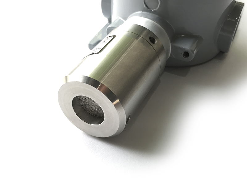
| Sensor housing / Rating |
SS316/SS304 housing with 316SS sintered filter / for Indoor use (buy the optional accessory rain-guard for outdoor installation) Exd versions for Zone 1/21 and 2/22. |
Note: Do not install the sensor where the ambient humidity is higher than 90% RH most of the time! It will cause the sensor to malfunction.
1.3 Cross-Sensitivity Data
What is cross-sensitivity?
The electrochemical sensor is normally affected by other gas. It meant the sensor not only measure the target gas but also the other gases. If there is a concentration of other gas, it would also cause the change in sensor output with a factor listed in the below table.
Please check the cross-sensitivity data of each gas type in this link.
2. Detail measurement principle
A special amplifier circuit amplifies the very low current from the gas sensor to deliver stable and high resolution.
The special mechanism provides noise filtering to deliver a very stable output. The ADC chip can provide a resolution from 16-bit to 24-bit.
The circuit will deliver the digital output to the reading device.
With an ultra-low-power design, it can run on battery for 10-20 years!
The EC sensor module will deliver 02 values:
- Gas concentration, in ppm or ppb.
- The temperature of the circuit board, in oC.
3. List of Measureable Gas/Volatile
| Index | Gas | Range (PPM) | Remarks |
| 1 | AsH3, Arsine | 0-1 | |
| 2 | CH2O, Formaldehyde | 0-10, 0-50, 0-1000 | |
| 3 | C2H4, Ethene, Ethylene | 0-10, 0-200, 0-1500 | |
| 4 | C2H4O, Ethylene Oxide | 0-10, 0-100, 0-1000 | |
| 5 | RCOOH, Organic Acids | 0-100 | |
| 6 | R3COH, Alcohols | 0-200 | |
| 7 | CO, Carbon Monoxide | 0-200, 0-500, 0-1000, 0-2000 | |
| 8 | CS2, Carbon Disulfide | 0-100 | |
| 9 | Cl2, Chlorine, Br2, Bromine | 0-20, 0-200 | |
| 10 | ClO2, Chlorine Dioxide | 0-5 | |
| 11 | H2, Hydrogen | 0-1000, 0-4000, 0-40000 | |
| 12 | H2O2, Hydrogen Peroxide | 0-100, 0-500, 0-2000, 0-5000 | |
| 13 | H2S, Hydrogen Sulfide | 0-50, 0-100, 0-500, 0-2000 | |
| 14 | HCl, Hydrogen Chloride | 0-20, 0-200 | |
| 15 | HF, Hydrogen Fluoride | 0-10 | |
| 16 | HCN, Hydrogen Cyanide | 0-50 | |
| 17 | NH3, Ammonia | 0-100, 0-500, 0-1000, 0-2000, 0-5000, 0-10000 | |
| 18 | NO, Nitric Oxide | 0-25, 0-250, 0-1000 | |
| 19 | NO2, Nitrogen Dioxide | 0-20, 0-100, 0-500 | |
| 20 | O2, Oxygen | 0-1%, 0-30%, | |
| 21 | O3, Ozone | 0-5, 0-100 | |
| 22 | PH3, Phosphine | 0-5, 0-20, 0-200, 0-2000 | |
| 23 | SiH4, Silane | 0-50 | |
| 24 | SO2, Sulfur Dioxide | 0-20, 0-100, 0-200, 0-1000, 0-2000, 0-10000 | |
| 25 | VOC, Volatile Organic Compound | 0-20, 0-2000 (equivalent Isobutylene) |
Applicable for: * Alcohols: Isopropanol, Methanol, Ethanol * Aldehydes and Ketones: Formaldehyde, Acetone, * Aromatic Hydrocarbons: Xylene, Toluene * Organic acids: Formic acid, Acetic acid, Commercial vinegar * Unsaturated Hydrocarbons: Isobutylene, Ethylene |
Please consult us to get detail specification of Gas sensor
4. Calibration of the Daviteq EC Gas Sensor
The Daviteq EC Gas Sensor must be connected to a reading device; normally, it is a wireless transmitter like Sub-GHz, Sigfox, or LoRaWAN.
In the reading device, the following parameter is configured in advance:
Sensor+amplifier sensitivity (mV/ppm): it is the voltage output of the amplifier circuit = Sensor current output (nA/ppm) x R_gain
For example, with an NH3 gas sensor, the default value of the Sensor current output is 110nA/ppm and R_gain = 100 Kohms.
Therefore, the default NH3 Sensor+amplifier sensitivity = 11 mV/ppm
Depending on the sensor type and R_gain value, the sensor sensitivity must be calculated and pre-configured into the reading device.
4.1 Why do we need to calibrate the gas sensor? There are some reasons:
- The sensor current output of a sensor is different from the other sensor. It is not the same value for all sensors after manufacturing.
- The sensor current output of a sensor will be changed over time. For example, the NH3 sensor current output will be reduced by about 5% of the signal per six months in clean air at 25 oC temperature.
- The R_gain of the circuit also has a 0.1% or 0.05% tolerance;
Therefore, users must calibrate the sensor before use or in a pre-defined interval (6 or 12 months, for example).
4.2 How to calibrate the EC Gas sensor?
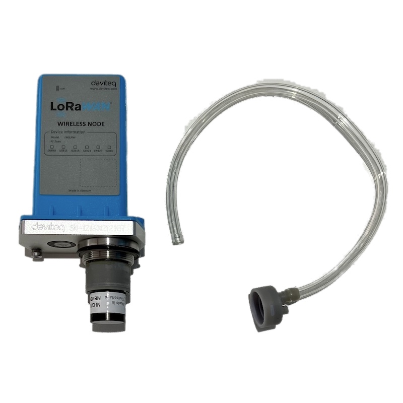
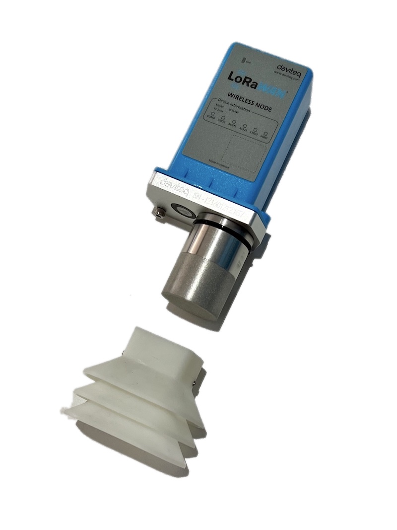
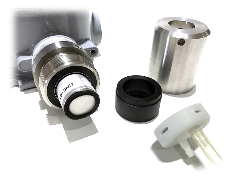
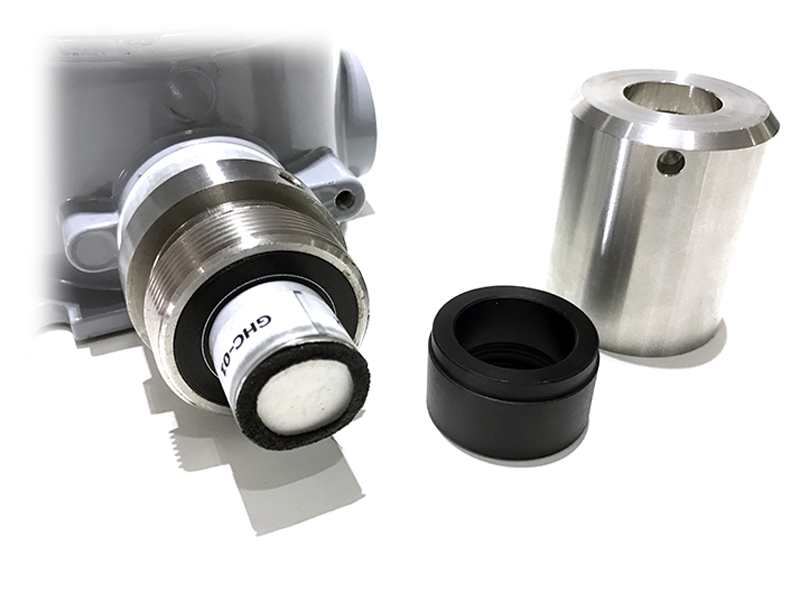
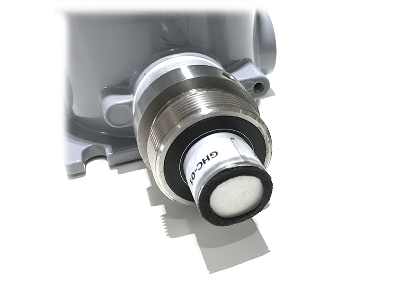
Instructions to attach the calibration cap onto the sensor module to get Zero or Span values.
|
Step 1. Remove the Filter and prepare the calibration cap
|
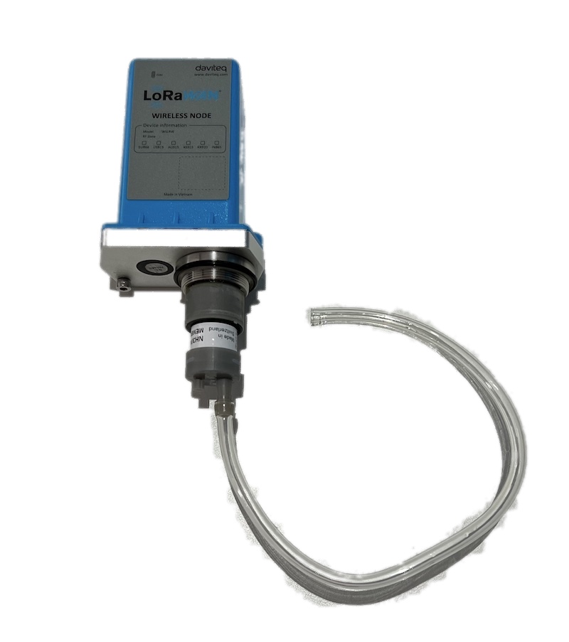
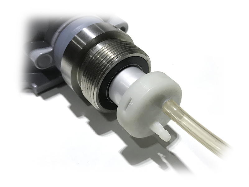
Step 2. Attach the calibration cap to the sensor head
|
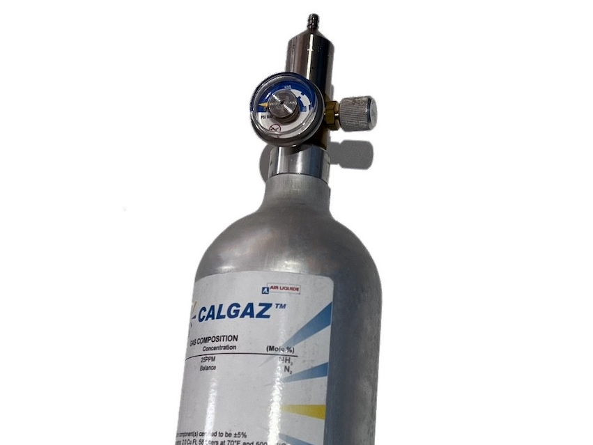
|
Step 3. Installed the Regulator to the Gas cylinder
|
Step 4. Attach the tube to the regulator
|
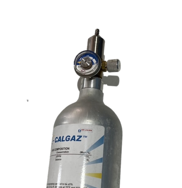
Please use the Flow Regulator with a flow rate of 2.5 LPM or 5.0 LPM.
With the 2-point calibration method, the user can define the A and B factors. Please find below the steps of calibration.
Step 1: Get the Zero value.
- Power ON the device;
- Place the device in a clean-air environment (the target value is nearly zero) at a temperature from 20 - 30 oC, in at least 60 minutes. Using the 99.99% Nitrogen gas as zero gas is better than clean air.
- After 60 minutes, force the device to send data, read and record the Raw_value.
- Recommendation: Record many Raw values at least 10 minutes apart (10 values).
Zero value is the average of the recorded Raw values
Note: the Raw_value can be positive or negative; it will be in the range of -3.00 to +3.00 ppm
Step 2: Get the Span value
Note: Keep the sensor Power ON all the time;
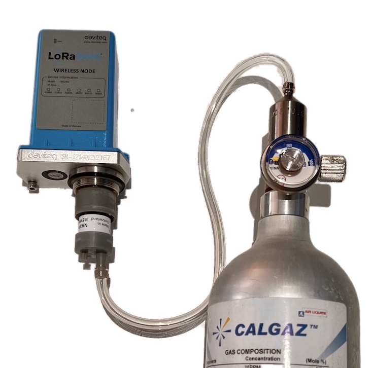
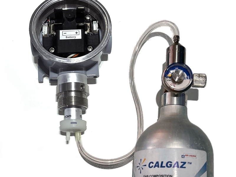
- Use the standard gas cylinder with a known concentration (for example, NH3 in N2 with a concentration of 25ppm or 50ppm) to supply the gas to the sensor;
- Use the calibration cap as above pictures to attach to the sensor and connect the tubing to the gas cylinder;
- Open the valve on the Cylinder slowly and make sure the gas has reached the sensor. Please use the Flow regulator 2.5 LPM or 5.0 LPM.
Notes:
- The tube length is short as possible to reduce the gas loss.
- Press a timer to start counting the time;
- After 2 minutes, force the device to send data once every minute, and stop forcing at 5 minutes. The highest Raw_value is the Span value.
Note: Get one value for Span
- After that, immediately turn OFF the valve to save the gas;
- Remove the calibration cap from the sensor;
- Place the sensor in clean air again.
Note: Always keep the sensor Power ON all the time;
DO NOT PLACE THE SENSOR IN THE SPAN GAS FOR MORE THAN 5 MINUTES; IT WILL SATURATE THE SENSOR OUTPUT AND DEGRADE THE SENSOR LIFE QUICKLY.
Step 3: Calculate the new A and B
-The calculation of new A and B values based on the basic linear formula: y = A * x + B
Where:
A and B are calibration coefficients
x is the sensor process value (example gas level in ppm) read on the reading device (RAW_VALUE in the payload), such as on the application server/network server, on the offline tool
y is the correct value. y is the value of standard gas/standard condition
Which condition of Zero value: y0=A * x0 + B
Which condition of Span value: ys=A * xs+ B
From the two formulas, the calculation of A and B as below
A = (y0 - ys) / (x0 - xs)
B = (ys * x0 - y0 * xs)/ (x0 - xs)
-Example of A, B calculation for LoraWAN Ammonia Gas sensor (item code WSLRW-G4-NH3-100-01):
* With the condition of a clean-air environment at a temperature from 20 - 30 oC, there is no ammonia gas (y0 = 0); while the NH3 level on the reading device (RAW_VALUE in the payload) is -0.25 (x0 = -0.25)
* When the sensor is connected to a standard gas cylinder having an ammonia level of 25 ppm (ys = 25); while the NH3 level on the reading device (RAW_VALUE in the payload) is 18.66 (xs = 18.66)
*The calculation of A and B for the Ammonia gas sensor:
A = (0 - 25) / (-0.25 - 18.66) =1.32205
B = (ys * x0 - y0 * xs)/ (x0 - xs) = (25 * (-0.25) - 0 * 18.66)/ (-0.25 - 18.66) = 0.33051
The factory default A = 1 and default B = 0
Use RAW_VALUE in the payload on the reading device for calibration
Step 4: Configure the new A and B into the device
- User can use the off-line tool or downlink to write the values of A and B;
- Writing the new A and B successfully meant you had done the calibration process. Congratulation!
5. Application notes for the Daviteq EC Gas Sensor
The applications will differ depending on the type of gas sensor used in the EC gas module. Please refer to some applications:
| Gas type | Typical applications |
| NH3 Ammonia Gas | NH3 leakage detection for HVAC, Chiller... NH3 concentration in the toilet NH3 concentration in the animal farms; chicken, pig, cow... NH3 concentration in the ambient air (Air quality monitor) |
| H2S |
H2S gas monitor for the sewage treatment system H2S gas monitor for basement floor H2S gas monitor for solid waste treatment plant... |
| Cl2 Chlorine gas |
Chlorine gas leakage detection in the chemical process plant Chlorine gas monitoring in ambient air in the water treatment plant Chlorine toxic gas monitoring in the City ... |
6. Installation notes
Notes:
* Avoid the place with humidity higher than 90% RH all the time (a short time in 2-3 days is acceptable)
* if the Sensor is intended to install outdoors, please use a rain guard to protect the sensor from rain and direct sunlight. Please contact us to buy this accessory.
- Place the sensor in the area to monitor the target gas concentration. Please always check the gas molecular weight v.s the air.
- For example, NH3 gas has a lighter weight than air, so the sensor must be placed at a height higher than the source of NH3 leakage. Normally, the sensor will be mounted at a height of 1.6m from the ground.
- For NH3 Odor detection in the toilet, users can place the sensor from 1.6m on the wall or on the ceiling which a height <= 2.6m
Note for Outdoor installation: For outdoor installation, please use the Rain guard to protect the sensor from raindrops or snowflakes. Please find below the steps for the installation
|
Step 1. Prepare the rain guard.
|
Step 2. Insert the rain guard into the sensor filter and tighten the locking screws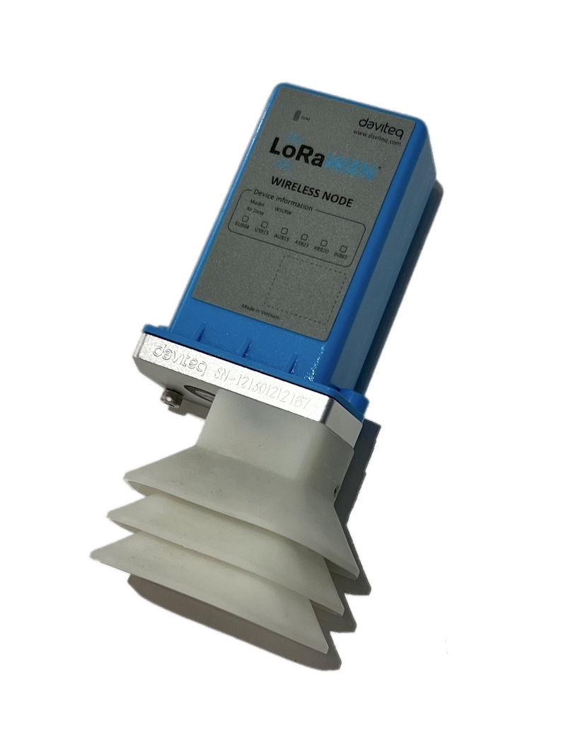 |
7. Troubleshooting for the Daviteq G4 Gas Sensor
| No. | Phenomena | Reason | Solutions | |
| 1 | The measured value is not within the expected value. | 1.1 | The sensor is drifted by time. | Re-calibrate the sensor |
| 1.2 | The sensor was continuously in a high-humidity environment (> 90% RH) for more than 03 days. | Place the sensor in low humidity for its recovery. It may take up to 30 days to recover. If the sensor cannot recover after 30 days, please replace the new sensor module. | ||
| 2 | The measured value is always zero or near zero. | 2.1 | The sensor module was removed. | Please check the sensor. |
| 2.2 | The sensor is at the end of its life. | Replace the sensor module | ||
| 3 | HW_Error = 1 | 3.1 | Loosed connection of sensor module and wireless transmitter. | Check the internal wiring. |
| 3.2 | The measuring module got a problem. | Please consult the manufacturer for a warranty or replacement. |
8. Maintenance of the Daviteq G4 Gas Sensor
| What? |
How? |
When? |
| Cleaning the Filter |
Check and clean the filter every few months, depending on the environment. Clean the filter with warm water and soap, then use compressed air to purge it from the inside out. |
Approx. 6-12 months (< 1 month for mining applications) |
| Re-calibration |
The gas sensor may be drifting over time. Please check the sensor specification to identify the interval time for the re-calibration sensor. Please follow the calibration procedure in section 3 above. |
Approx. 6-12 months |
| Sensor replacement |
Replace the new sensor module after 02 years of operation (please check the sensor specification of each gas type). Please see the below instructions. |
Approx. 2 years |
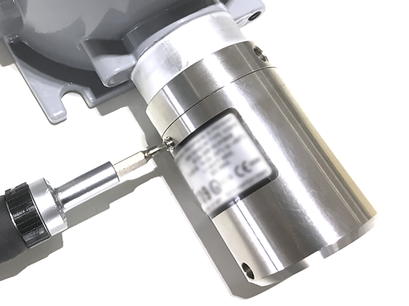
Sensor replacement instructions:
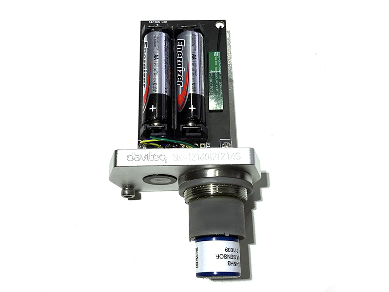
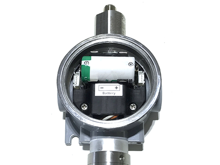
* Please remove the batteries before doing the following steps
|
Step 1. Remove the filter
|
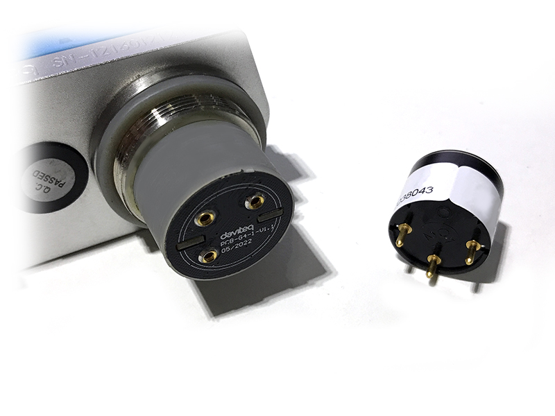
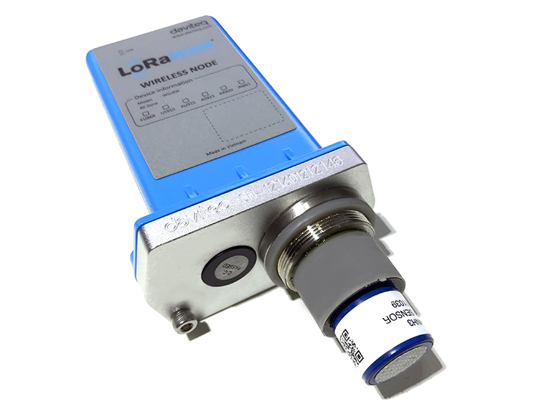
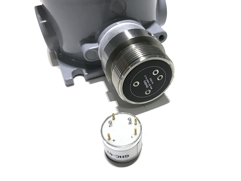
Step 2. Unplug the sensor module
|
|
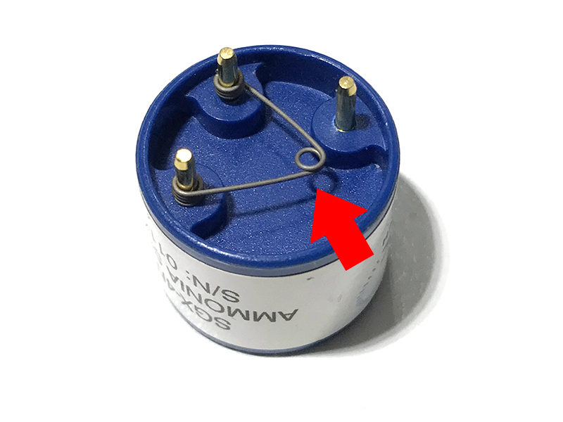
Step 3. Remove the spring clip on the new sensor module.
|
Step 4. Plug the new sensor module into the PCB
|
|
Step 5. Insert the batteries and start calibration of the new sensor as per section 3.
|
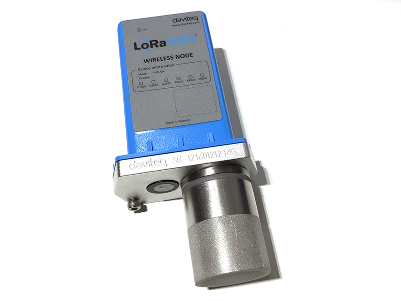
Step 6. Place the filter back.
|
9. Default configuration
This G4 gas sensor module has the default configuration. However, those parameters can be changed. The user can change the configuration on the wireless transmitter so that the complete sensor (transducer + wireless) delivers the proper output value. Below are some configuration parameters that store in the flash memory of the wireless transmitter.
| Description | Unit | Default | Format | Property | Comment |
| CONSTANT_A | 1 | Float | R/W |
Constant a for scaling measured value |
|
| CONSTANT_B | 0 | Float | R/W |
Constant b for scaling measured value |
|
| HIGH_CUT | 1E+09 | Float | R/W |
High cut value for scaled_value |
|
| LOW_CUT | 0 | Float | R/W |
Low cut value for scaled_value |
|
| SENSOR+AMPLIFIER SENSITIVITY | mV | Float | R/W |
Default = 11 for NH3 gas sensor |
END.
DAVITEQ FORMALDEHYDE GAS SENSOR CH2O, 10 PPM, SERI-4
SENSOR SPECIFICATION
| MEASURING SPECIFICATION | |
| Sensor type | Daviteq Seri-4 electro-chemical gas sensor |
| Nominal range | 0-10 ppm |
| Maximum overload | 30 ppm |
| Filter | - |
| Resolution | 0.01 ppm |
| T90 response time | < 30 s |
|
Typical Baseline Range (pure air, 20°C) |
-0.1 ppm .. + 0.1 ppm |
| Repeatability | < 2% of reading |
| Accuracy | < +/- 5% of reading |
| WORKING CONDITIONS | |
| Relative humidity range |
15 % to 90 % RH non-condensing |
| Temperature range |
-40 °C to 50 °C |
| Pressure range |
Atmospheric ± 10% |
| SENSOR LIFETIME | |
|
Expected Operation Life |
3 years in the air |
|
Expected Long-Term Output Drift in air |
< 2 % of reading loss per month |
We have other ranges: 50 ppm, and 1000 ppm.
CROSS SENSITIVITY DATA
|
Interfering Gas |
Concentration (ppm) | Reading (ppm) |
|
CO2 |
100 | < 20 |
|
Ethanol (C2H5OH) |
30 | 1 |
| H2 | 100 | 5 |
| H2S | 20 | ~ 20 |
| Methanol (CH3OH) | 80 | 10 |
| Methyl Mercaptan (MM, CH3SH) | 10 | ~6 |
| Tert-Butyl Mercaptan (TBM, (CH3)3CSH) | 10 | ~6 |
PID GAS SENSORS
Miniature PID Gas Sensor
Features
-
Patented ‘fence’ electrode for excellent humidity resistance (from iOnScience)
-
Anti-contamination design
-
Reliable lamp ignition – illuminates at low temperatures
-
Superior lamp life – 10.6 and 10.0 eV => 10,000 hours
-
User-replaceable electrode stack in event of corrosive or mechanical damage
-
Lamp out error detection (for Range 0-4000 PPM only)
Applications
-
Industrial hygiene & safety monitoring
-
Soil contamination and remediation
-
Hazmat sites and spills
-
Leak detection
-
EPA Method 21 and emissions monitoring
-
Arson investigation
-
Indoor air quality monitoring
-
Outdoor air quality monitoring
1. Selectable Ranges (Isobutylene equivalent) & Performances:
- Range: >10,000 ppm. Minimum detection limit: 500 ppb (10.6 eV Lamp). Response time in diffusion mode (T90) < 3s
- Range: 0 to 4000 ppm. Minimum detection limit: 100 ppb (10.6 eV Lamp). Response time in diffusion mode (T90) < 3s
- Range: >200 ppm. Minimum detection limit: 20 ppb (10.6 eV Lamp). Response time in diffusion mode (T90) < 8s
- Range: 0 to >100 ppm. Minimum detection limit: 5 ppb (10.0 eV Lamp). Response time in diffusion mode (T90) < 8s
- Range: 0 to >100 ppm. Minimum detection limit: 100 ppb (11.7 eV Lamp). Response time in diffusion mode (T90) < 8s
- Range: 0 to >40 ppm. Minimum detection limit: 1 ppb (10.6 eV Lamp). Response time in diffusion mode (T90) < 8s
- Range: 0 to 3 ppm. Minimum detection limit: 0.5 ppb (10.6 eV Lamp). Response time in diffusion mode (T90) < 12s
Environment:
- Relative humidity range: 0 - 99% RH, non-condensing;
- Operating Temp Range: -40 °C to +55 °C ( except 0 - 40 °C for Range 3PPM sensor)
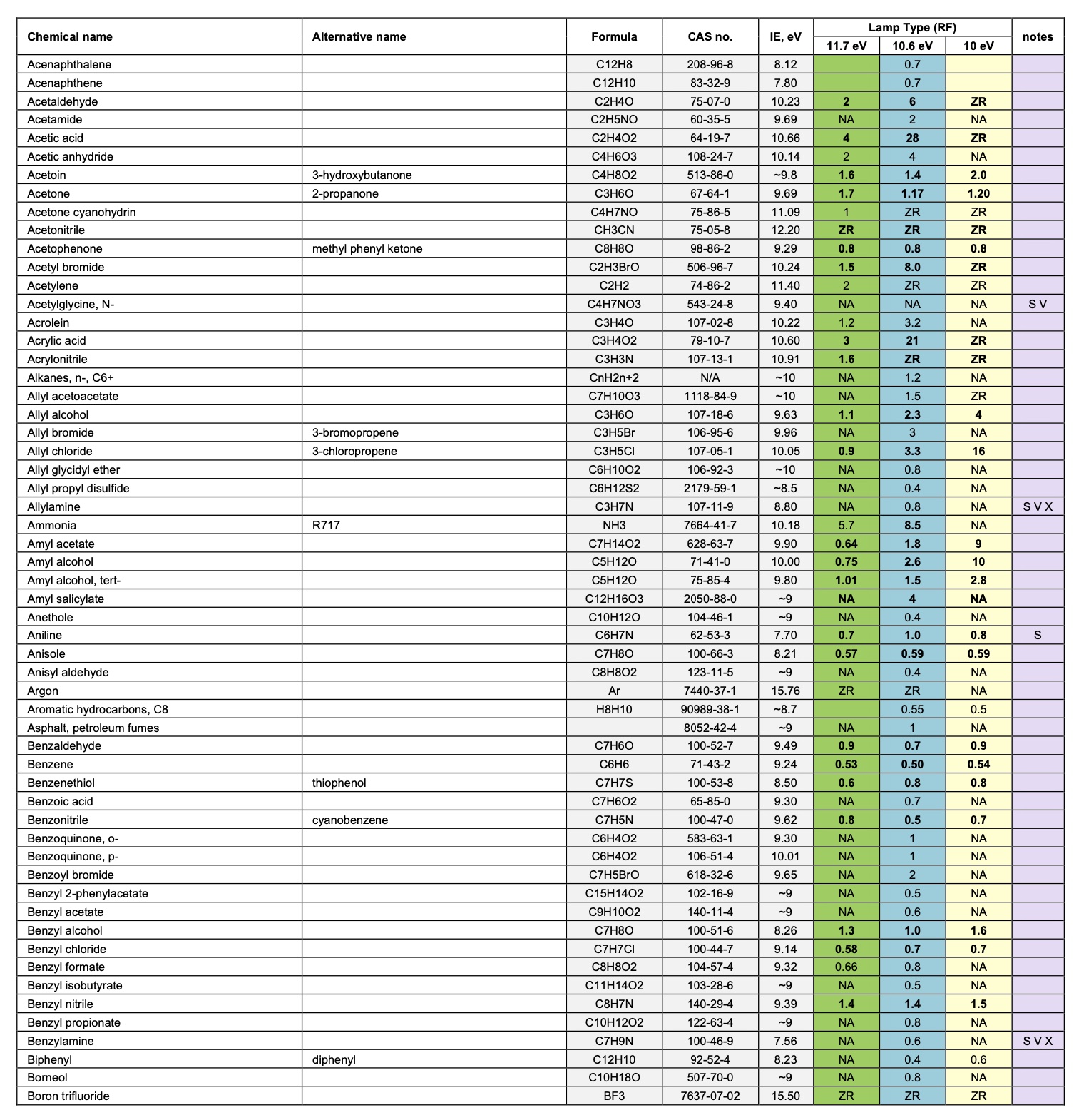
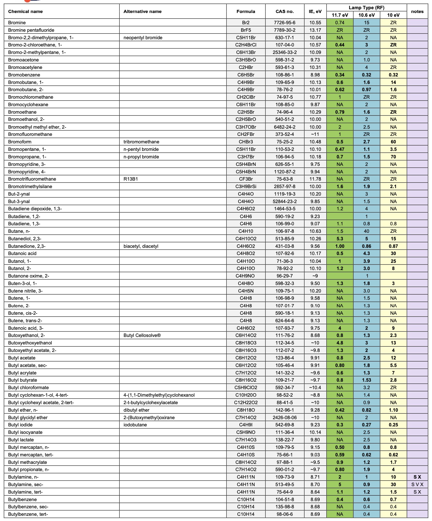
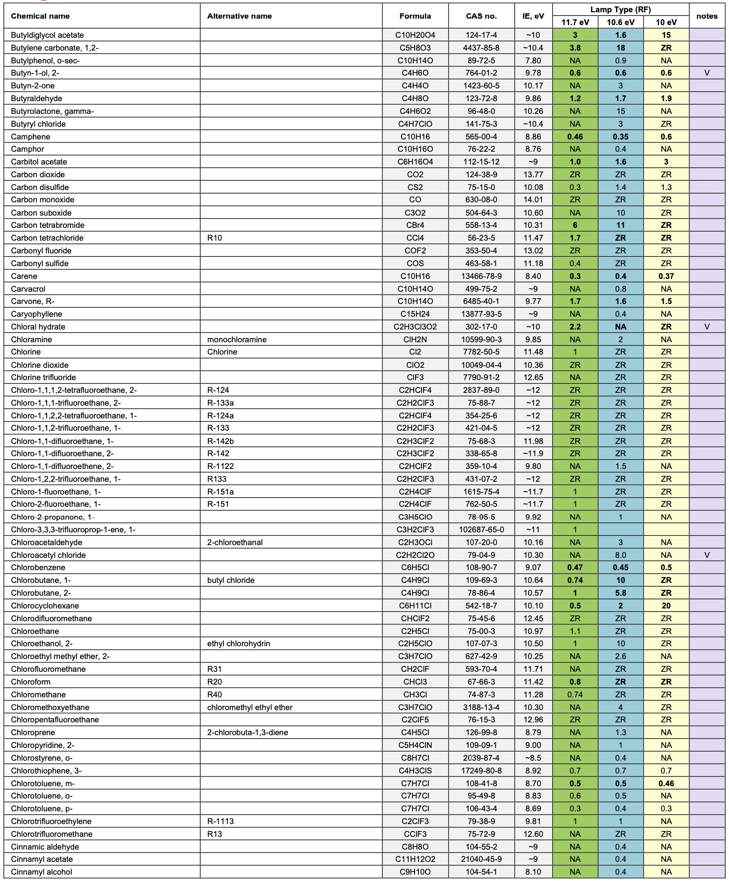
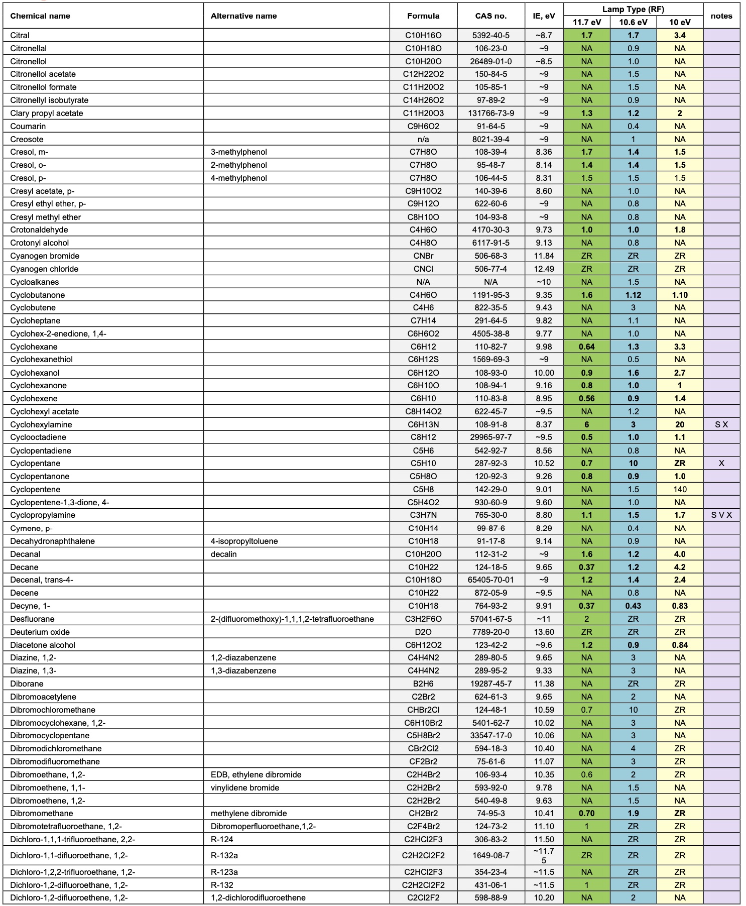
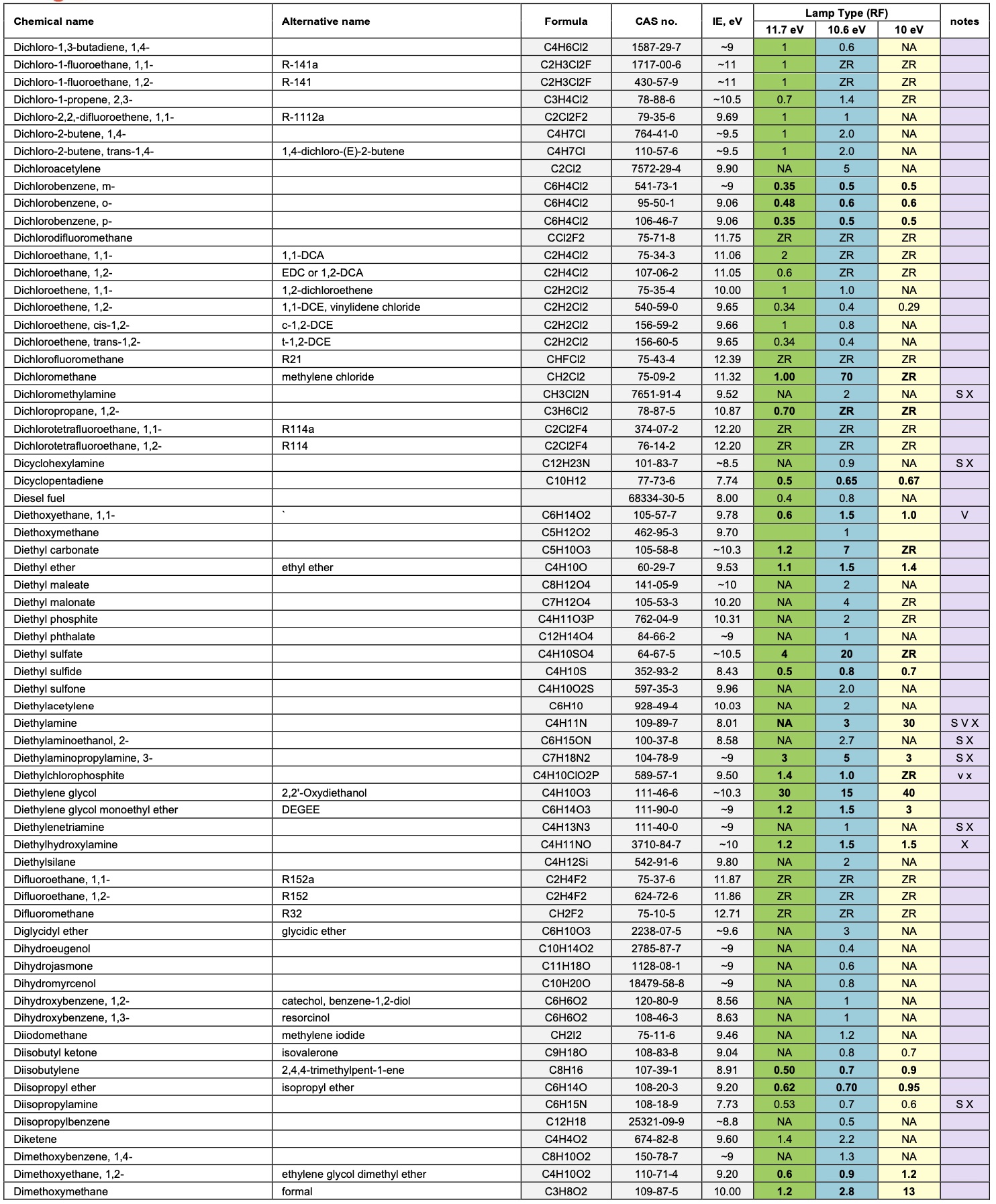
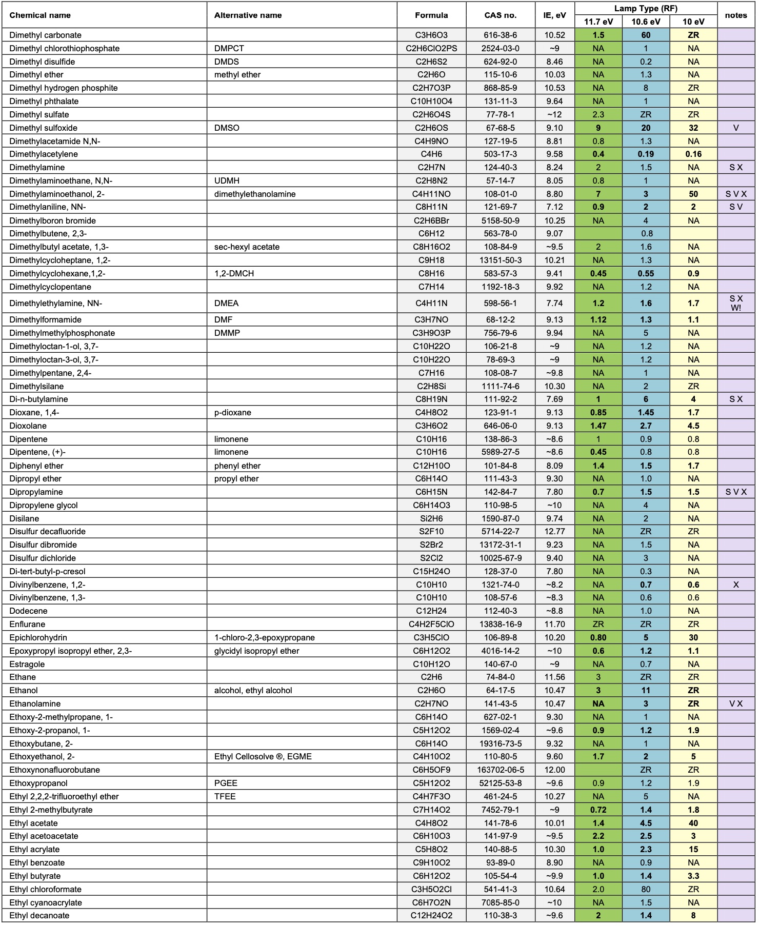
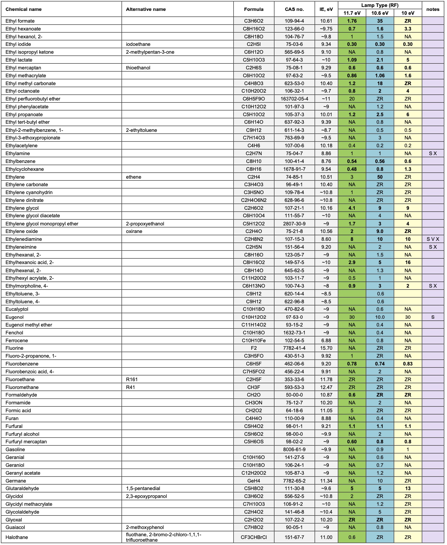
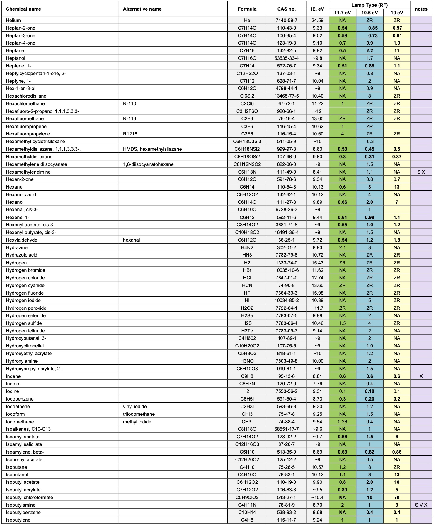
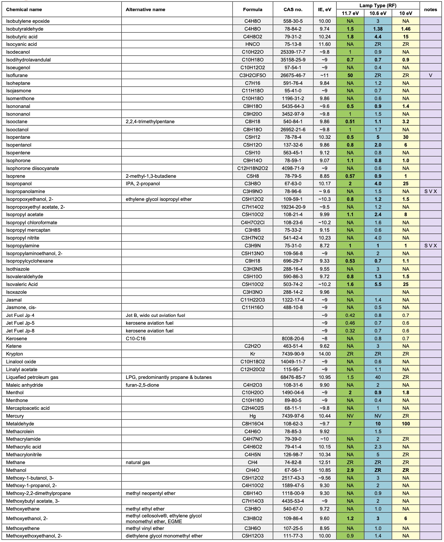
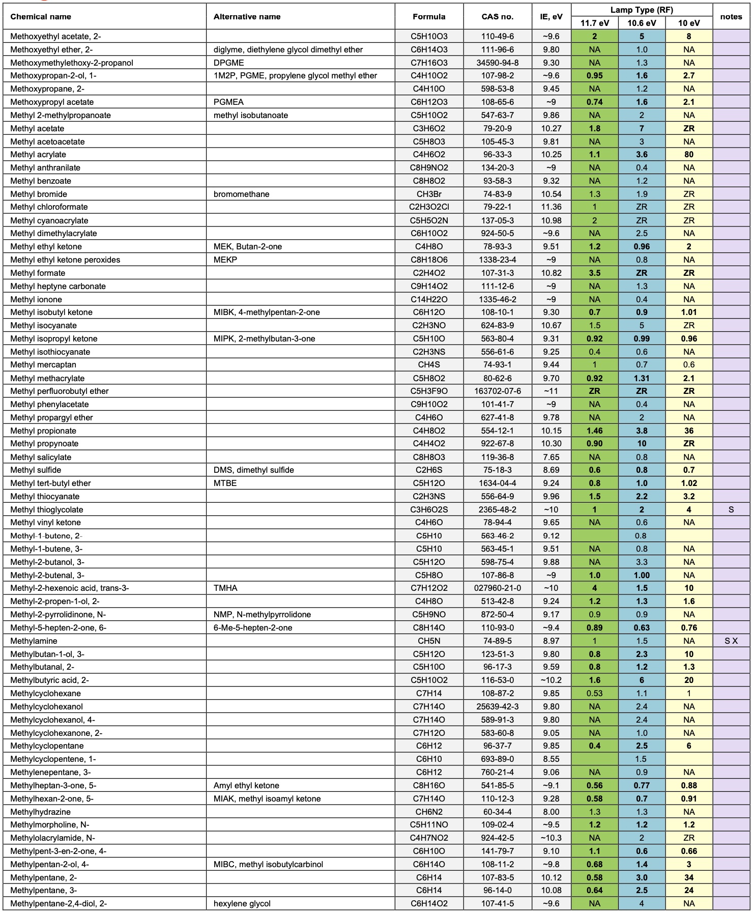
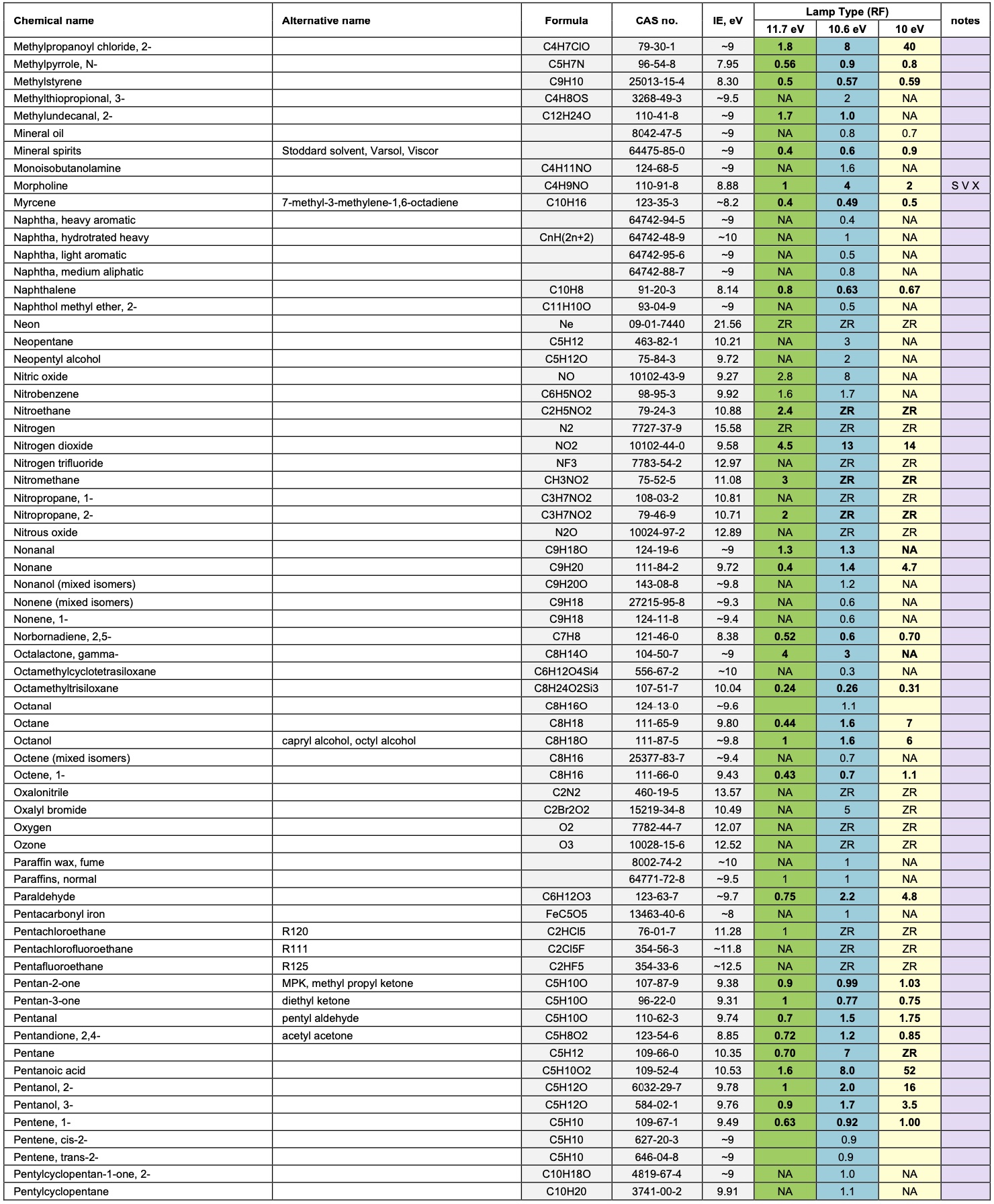
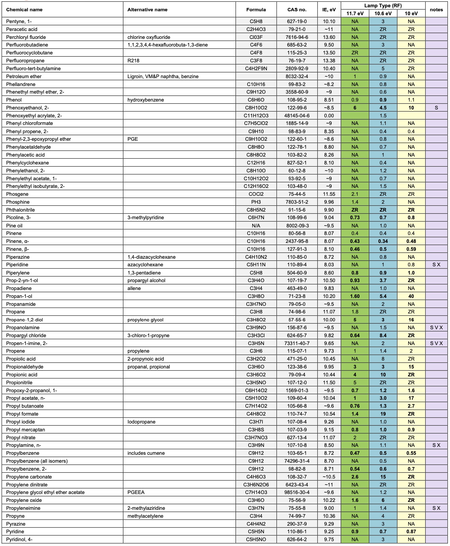
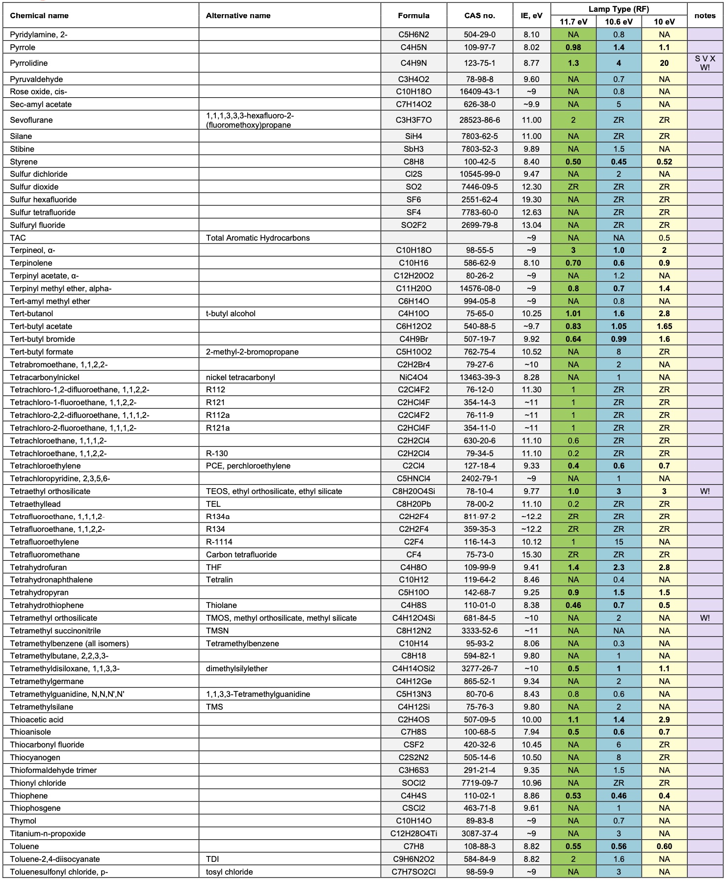
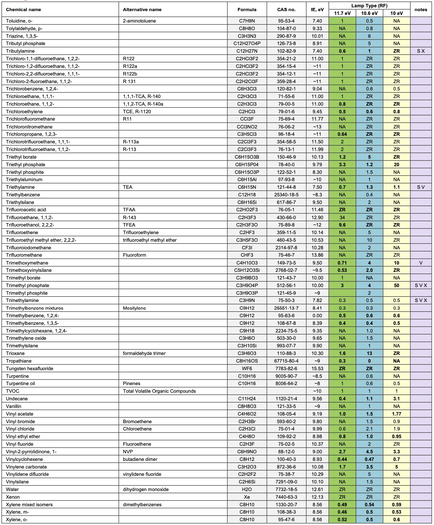
2. Response Factors for other Gases:
Our PIDs are calibrated using isobutylene, but PID is a broadband detection method with a variable sensitivity to each VOC. The relative sensitivity to each compound also varies significantly with PID photon energy (10, 10.6 or 11.7 eV). It varies much less with PID design and lamp output.
Response Factors (RFs) provide an indication of the relative sensitivity of PID to specific VOCs, relative to isobutylene. The RF of a VOC is used to convert the calibrated response of the sensor with isobutylene into a concentration of the target VOC.
Example: Toluene
-
A PID 10.6 eV sensor is calibrated with isobutylene and found to have a sensitivity of 1 mV ppm-1.
-
If the sensor is exposed to 100 ppm isobutylene the output will be 100 mV.
-
The response factor for toluene using 10.6 eV is listed as 0.56.
-
If the sensor is exposed to 56 ppm toluene then the displayed uncorrected concentration will be 100 ppm
isobutylene. The corrected concentration would be 100 multiplied by the RF, 0.56, which gives the correct result of 56ppm toluene.
A complete list of response factors is shown below.
If response factors are programmed into an instrument, it is possible for target VOC to be specified, and the instrument can then display and record a concentration for that target volatile.
The Notes column below identifies the following:
S: slow. PID requires at least 30 s for a stable response.
V: Variable response. The response is susceptible to small changes in ambient conditions, particularly humidity.
X: Temporarily contaminating. PID responsivity may be suppressed for at least 30 min after 100 ppm-min exposure.
W!: Expected to cause PID lamp window fouling. May require regular bump tests and window cleaning.

Calculating the sensor responsivity to VOC mixtures
A volatile organic compound, or VOC, is a carbon-containing chemical, which is significantly or completely vaporised at ambient temperatures.
Occasionally you will be measuring a mixture of VOCs. If the total concentration is within the linear range of the PID, then it is reasonable to assume that the concentrations are additive without interference between the different VOCs:
The correction factor for a gas mix containing PID detectable gases A, B, C... with response factors RF(A), RF(B), RF(C), in fractional proportions a:b:c is given by:
RF mix = 1/[a/RF(A) + b/RF(B) + c/RF(C)...]
Example: A gas mix to be monitored contains 1 part isopropanol to 4 parts acetone:
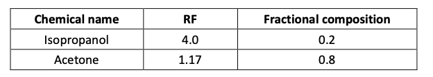
Therefore the RF of the mix will be:
RF mix = 1/[(4.0 x 0.2) + (1.17 x 0.8)] = 1/(0.8 + 0.936) = 0.58
Important: remember that if you are measuring a combination of VOCs then accurate measurement of one of these VOCs will be difficult; without careful data analysis you will get only a RF averaged measurement. Also, note that in the volatilisation of mixtures of VOC’s of different volatility, the more volatile fraction volatilises most rapidly, and the least volatile most slowly, leading to a change in the composition of the liquid and vapour mix.
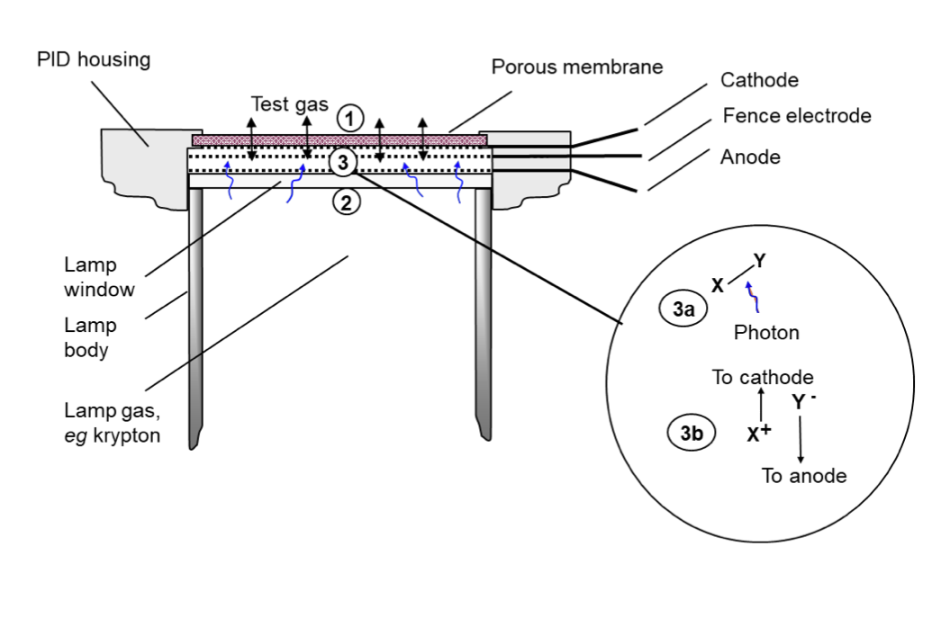
How PID Sensor works?
The PID sensor measures volatile organic compounds (VOCs) in air by photoionisation detection (PID). The sensing mechanism is shown schematically below. Test gas (1) is presented to the external face of a porous membrane, through which it freely diffuses, into and out of a gaseous enclosure, (shown by double headed arrows). From the opposite face of the enclosure, (2) an illuminated lamp emits photons of high energy UV light, transmitted through a crystal lamp window (wavy arrows). Photoionisation occurs in the enclosure when a photon collides with a photoionisable molecule (3a) to generate two electrically charged fragments or ions, one positively charged, X+, and one negatively charged, Y- (3b). These are separated at, oppositely charged metal electrodes, being a cathode and anode, generating a tiny electric current. The current is amplified in an electric circuit (not shown) and presented as a sensor voltage output which depends on the concentration of photoionisable gas. The MiniPID 2 includes a third fence electrode which ensures that the amplified current does not include significant contributions due to other current sources such as electrolytic salt films on the chamber walls.
Volatile organic compounds (VOCs) sensed by PID sensor
Most VOCs can be detected by PID sensor. Notable exceptions are low molecular weight hydrocarbons.
Every VOC is characterised by an Ionisation Energy (IE). This is the minimum energy required to break the VOC into charged fragments or ions. Volatiles and gases in air are photo-ionised, and hence detected, when exposed to light of photon energy greater than their IE. PID sensor is provided with a light source of three different photon energies: 10.0 eV, 10.6 eV or 11.7 eV.
Standard PID sensors (PPM, PPB and HS) engage an unfiltered krypton light source, which delivers 10.6 eV UV light. The sensors respond to about 95% of volatiles, notable exceptions being most volatiles of one carbon atom, acetylene, ethane, propane and saturated (H)CFC’s
The PID 11.7 eV, which employs an argon lamp light source, responds to almost all VOCs: the few exceptions are methane, ethane and saturated fluorocarbons. 11.7 eV PID is less selective but particularly of interest in measuring formaldehyde, methanol and the lighter hydrocarbons, for which scant other sensing technology is available.
Finally, PID 10.0 eV, which engages a krypton light source and a crystal filter, responds to more limited range of VOC’s. Aromatics and most other unsaturated molecules are most readily detectable with this lamp, whereas most saturated hydrocarbons, with which they often occur, are sensed more weakly or not at all.
For detection of a volatile compound, it must be sufficiently volatile. A fairly large molecule such as alpha-pinene, (a constituent of turpentine), saturates in air at about 5000 ppm at 20 oC; this is the maximum concentration of the alpha-pinene that can be measured at 20 oC. Some compounds, e.g. machine oils and plasticisers, generate a fraction of a ppm of vapor at ambient temperatures. Because the diffusion of such large molecules is also very slow, in most scenarios they are not detectable. Organic compounds of boiling points 275 to 300 oC (at 1 atm.) are considered to be semi-volatiles and marginally detectable. Compounds of boiling point > 300 oC are considered non-volatile and undetectable.
Installation Notes
-
If the PID is deployed in a wall mountable detector, the sensor is ideally located in the instrument to be as far from the wall mountings as possible, to minimise condensation phenomena caused by the air vs wall temperature disparity (consider the accumulation of particulates and heavy volatiles on shelves and kitchen units).
-
The sensor should be pointing downwards or sideways, to avoid slow accumulation of volatile in the sensor cavity, and dust.
Error States
| Sensor Types |
Fault Condition
|
Recommended Action |
|
| 0-4000 ppm Sensor | All others | ||
| Error 4 | N/A |
Lamp not illuminated |
Change or clean lamp |
| Electrode stack not fitted correctly |
Ensure electrode stack is fitted correctly |
||
| Error 3 | Error 3 |
Oscillator not working |
Change the PID |
|
Misplaced electrode stack |
Change electrode stack |
||
| Error 2 | Error 2 |
Oscillator overloaded |
Change electrode stack and/or PID |
| Error 1 | Error 1 |
Power removed |
Consult manufacturer |
Calibration Guidelines
PID sensor naturally produces ozone in air, which over time acts to remove organic detritus from within the PID cavity. In many domestic and light industrial environments, the PID is self-cleaning. Re-calibration is then only needed to adjust for any decay in the PID lamp output on which the photoionisation measurement depends. In a fixed instrument, typically this will be every one to two months of cumulative sensor operation. However, when first deploying a PID instrument in a new environment, end users should be encouraged to bump test and re-calibrate as necessary. Since portable PID instruments are exposed to unknown environments, their calibration may be required more often.
Calibration of instruments containing PID usually demand measurements of ‘zero gas’, containing near zero concentrations of VOCs, and a span gas, used to calibrate the PID sensor in its linear range. Both gases are usually prepared with a ‘balance’ gas of artificial air, comprising ~80% nitrogen and ~20% oxygen. Do not use pure nitrogen as a balance gas as this delivers up to 20% more responsivity than air.
Appropriate end user calibration gases for the various MiniPID 2 sensors are identified below:
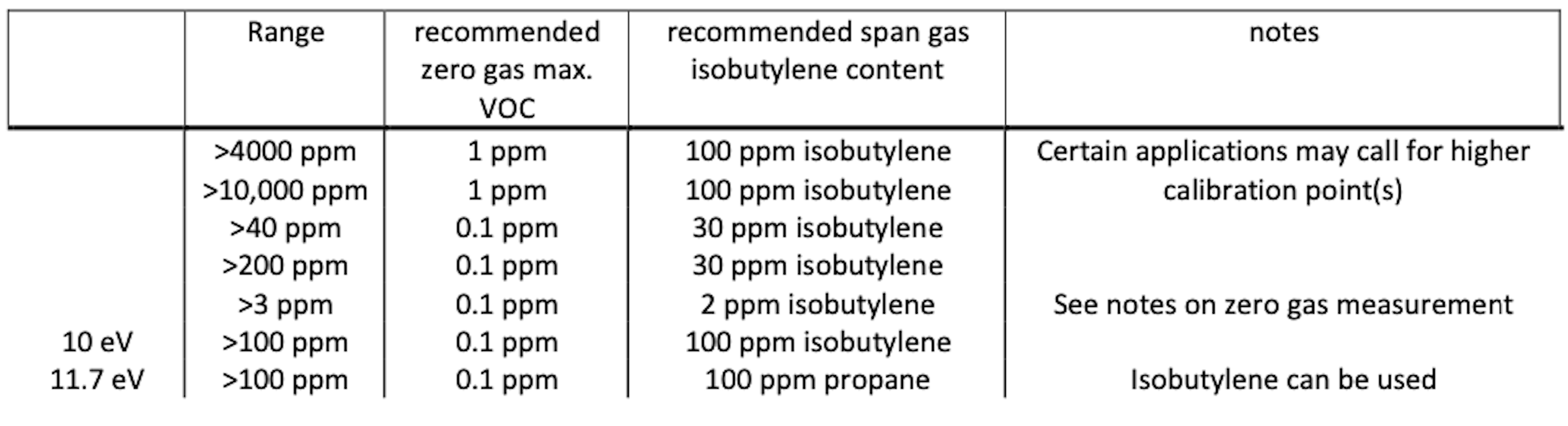
Zero gas of <0.1 ppm VOC is usually provided by ultrahigh purity (UHP) air. To enable frequent calibration, purified gas systems providing the same gas purity can be used. Lubricating oils in compressed air lines should be avoided as they will foul PIDs if exposed to the gas stream for extended times.
Some gases absorb UV light without causing any PID response (e.g. methane, ethane). In ambient atmospheres where these gases are present the measured concentration of target gas will be less than is present. Methane absorbs UV strongly, so for accurate measurements in methane containing atmospheres, calibrate with a calibration gas containing the expected methane concentration.
The HS sensor requires particular care in handling as identified in the technical article TA-14. Since air may contain semi-volatiles which give rise to a significant and slowly moving sensor response, calibration of a high sensitivity VOC detector must always be undertaken after burn-in using clean air. This will provide the zero point calibration reading.
Maintenance
Routine Maintenance
The electronics in the PID sensor are not accessible and designed to be maintenance-free.
The electrode stack is easily replaced and inexpensive. The PID stack will operate for years in most non-corrosive environments. It is recommended that end users of instruments containing PID carry at least one electrode stack in stock. The electrode stack is not toxic. Due procedures should be considered for safe disposal in the event of the stack being exposed to toxic environments.
Unscheduled Maintenance
The PID should be dismantled and stack and lamp inspected in the following circumstances:
-
On exposure of the sensor to very humid, acidic (sour) and salty environments. This may cause inorganic salts to accumulate on PID enclosure walls, which ultimately compromises the screening potential of the PID fence electrode. This is often indicated by a moisture sensitive signal.
-
Visual indications of liquid ingress into the electrode stack.
-
A sensor error 4 indicates a failure of contact has developed between the sensor pins and the stack pads. The wings on the PID stack may fail after repeated dis- and re-assembly. It may also be caused by failure of the stack to engage fully with the sensor body, which may be corrected by refitting the lamp and stack. The PID lamp should be cleaned and replaced as necessary if the responsivity of the sensor, as measured in bump tests or during calibration, decreases unexpectedly. Note that exposure of the sensor to amines is liable to temporarily contaminate the PID lamp. Instrument design should cater for this.
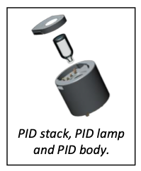
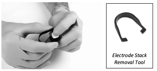
Removing the electrode stack and lamp
CAUTION: Only use the electrode stack removal tool. Any other tools (for example screwdrivers) may damage your PID body and will invalidate your warranty.
-
-
Wear gloves. Carefully remove the sensor from instrumentation.
-
Locate electrode stack removal tool in the side slots of the PID and squeeze together until electrode stack and lamp are released.
-
Lift carefully the PID body away from the electrode stack and lamp.
-
Occasionally the lamp may be temporarily lodged in the sensor body and will need to be freed carefully with tweezers. Occasionally the small spring behind the lamp will come out when the lamp is removed from the sensor. Simply replace it into the sensor body.
-
Inspecting the PID stack
On removal of the electrode stack, carefully inspect the underside. The visible electrodes should be shiny and metallic. If there are any signs of corrosion or water ingress the stack should be replaced.
Inspecting and cleaning the PID
NOTE: Alumina polishing of lamps described below is appropriate for all
PID lamps except the PID 11.7 eV lamp.
Inspection of the PID lamp, as shown in the illustration, may reveal a fine film of contamination on the lamp window. However, it should be noted that window contamination is frequently not visible. Black or metallic deposits on the interior face of the lamp cannot be removed. If the deposits are extensive, the lamp must be replaced.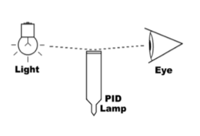
To clean the lamp, use of PID lamp cleaning kit A-31063. Validity of lamp warranty is compromised if lamp cleaning maintenance is not followed and lamp has obvious fouling/contamination.
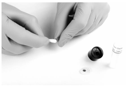
-
Wear gloves. Never touch the lamp window, even with gloves.
-
Open the container of alumina polishing compound.
-
With a clean cotton bud, collect a small amount of the powder.
-
Use this cotton bud to polish the PID lamp window. Use a circular action, applying light pressure to clean the lamp window. Do not touch the lamp window with fingers.
-
Continue polishing until an audible “squeaking” is made by the cotton bud moving over the window surface. Usually this requires 15 to 30 s polishing.
-
Remove the residual powder from the lamp window with a clean cotton bud. Care must be taken not to touch the tips of cotton buds that are to be used to clean the lamps.
-
Ensure the lamp is completely dry and all detritus is removed before reassembling the lamp stack and body (see below).
-
Re-assemble the sensor lamp, stack and sensor body as described below, and reinstall sensor in the instrument.
-
Bump test the sensor. If the responsivity has recovered, then recalibrate the instrument. If not, replace the lamp.
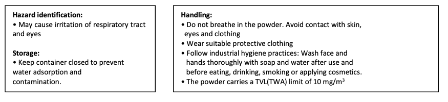
CAUTION: The lamp cleaning kit contains alumina (CAS Number 1344-28-1) as a very fine powder. Cleaning should be undertaken in a well-ventilated area. A full material safety data sheet MSDS is available on request from Ion Science Ltd. Key safety issues are identified below:
Assembly of MiniPID 2 electrode stack, lamp and body.
CAUTION: Do not assemble using a damaged lamp as this may rupture the stack’s lamp O-ring seal.
-
Lay the electrode stack front face down on a clean, flat surface and then screw the lamp down into the O-ring until it firmly abuts against the front electrode face.
-
Place the PID body carefully down over the lamp-stack sub-assembly so as not to disturb its seating within the electrode stack and then push the body firmly onto the face down electrode stack so that both wings engage with the PID body.
-
Inspect the sensor to confirm that both wings of the electrode stack have engaged with the PID body.
-
Refit the sensor into the sensing instrumentation.
-
Re-calibrate the equipment in accordance with manufacturer’s instructions.
Instrument Warranty and Service
Warranty
The standard warranty on a PID is 12 months.
Service and service centers
Daviteq is pleased to offer a number of service options for our PID product range that allows you to choose the cover that best suits your needs.
Contact Daviteq or your local distributor for service options in your area.
NDIR GAS SENSOR
Daviteq NDIR Gas Sensor
1. Introduction
1.1 Overview
Daviteq NDIR Gas sensor module is intended for automatically continuously measuring hydrocarbons or carbon dioxide concentration in the atmosphere. The sensor operating principle is based on NDIR technology, i.e., on selective absorption of LED-produced infrared radiation by gas molecules. The differential dual wavelength method allows the elimination of water vapor, optical elements contamination, and other non-selective hindrances influence.
It has ultra-low power consumption to allow it to be integrated with Wireless Devices such as Sub-GHz transmitters, Sigfox transmitters, LoRaWAN transmitters, RS485 output transmitters, etc.
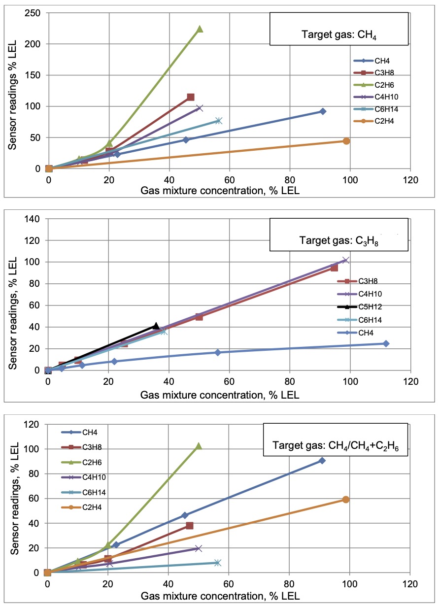
It can be calibrated with target gas like CO2, CH4, C3H8, C2H4, and C2H6...
Typical Applications: Flammable gas detection and CO2 gas monitor.
1.2 Specification
| Sensor technology | LED-based NDIR |
| Gas sampling method | Diffusion |
| Sensor housing / Rating |
SS316/SS304 housing with 316SS sintered filter / for Indoor use (buy the optional accessory rain-guard for outdoor installation), Exd approval for Zone 1/21 or Zone 2/22 installation. For mining applications: please add extra dust filter to protect (please contact us for this accessory) |
| Target gas | CO2, CH4, CH4/CH4+C2H6, C3H8, C2H4,... please consult us for other HC gases |
| Ambient Humidity | 0 - 98% |
| Temperature | -40 .. + 60 oC |
| Atmospheric pressure | 80 .. 120 kPa |
| Warm-up time | 120 sec |
| Measurement range, % vol. |
0...1.5 (CO2 or C3H8 sensors) 0...2.5 (CH4 or C3H8 sensors) 0...5 (CH4 or CO2 sensors) 0...100 (CH4 sensors) |
| Reading Stability in +20 .. + 25 oC |
± 0.1% vol. or ± 5% of readings (whichever is greater) for CH4 ± 0.05% vol. or ± 5% of readings (whichever is greater) for C3H8 / CO2 |
| Zero Stability in +20 .. + 25 oC |
for CH4: ± 0.1% vol. or ± 2% LEL |
| Response time T90 | <= 30 sec (with sintered metal filter) |
| Sensor lifetime | >= 10 years |
| Calibration interval | Recommend recalibrating zero and span at least every 30 months |
Detailed reading stability
| Calibration Gas |
Readings stability within a temperature range |
Additional variability due to pressure |
Additional variability due to humidity |
| CH4 |
± 0.1% vol. or ± 5% of readings (whichever is greater) within the range of +20...+25 °C; |
± 0.2% vol. or ± 30% of readings (whichever is greater) at 100 kPa (test: 80 kPa, 100 kPa, 120 kPa) |
± 0.2% vol. or ± 15% of readings (whichever is greater) at 40 °C (test: 20% RH, 50% RH, 90% RH) |
|
± 0.2% vol. or ± 10% of readings (whichever is greater) within the range of |
|||
|
± 0.4% vol. or ± 20% of readings (whichever is greater) within the range of |
|||
| C3H8 |
± 0.05% vol. or ± 5% of readings (whichever is greater) within the range of +20...+25 °C; |
± 0.1% vol. or ± 30% of readings (whichever is greater) at 100 kPa (test: 80 kPa, 100 kPa, 120 kPa) |
± 0.1% vol. or ± 15% of readings (whichever is greater) at 40 °C (test: 20% RH, 50% RH, 90% RH) |
|
± 0.1% vol. or ± 10% of readings (whichever is greater) within the range of |
|||
|
± 0.2% vol. or ± 20% of readings (whichever is greater) within the range of |
|||
| CO2 |
± 0.05% vol. or ± 5% of readings (whichever is greater) within the range of +20...+25 °C; |
± 0.1% vol. or ± 40% of readings (whichever is greater) at 100 kPa (tested at 80 kPa, 100 kPa, 120 kPa)
|
± 0.1% vol. or ± 15% of readings (whichever is greater) at 40 °C (tested at 20% RH, 50% RH, 90% RH)
|
|
± 0.1% vol. or ± 10% of readings (whichever is greater) within the range of -10...+20 °C and +25...+40 °C; |
|||
|
± 0.2% vol. or ± 20% of readings (whichever is greater) within the range of -20...-10 °C and +40...+50 °C. |
1.3 Cross-Sensitivity Data
What is cross-sensitivity?
The gas detection sensor is usually affected by other gas. It meant the sensor not only measure the target gas but also the other gases. A concentration of additional gas would also cause a change in sensor output with a factor listed in the table below.
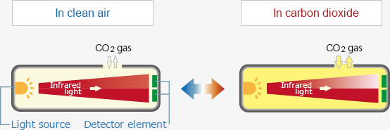
2. Principle of operation
When infrared radiation interacts with gas molecules, infrared light is absorbed by the gas molecules at a particular wavelength, causing vibration of the gas molecules. NDIR (Non-Dispersive Infrared) gas sensors detect a decrease in transmitted infrared light, which is in proportion to the gas concentration. This transmittance, the ratio of transmitted radiation to incident energy, depends on the target gas concentration.
NDIR gas sensors consist of an infrared source, detector, optical filter, gas cell, and electronics for signal processing. A single light source, dual wavelength type gas sensor has two detectors and two optical filters of different wavelengths, which are placed in front of each detector. The infrared light that is absorbed by a target gas passes through the active filter with a particular bandwidth to detect the target gas. The infrared light that does not interact with the target gas passes through the reference filter. The difference between transmitted light intensities in these two bandwidths is converted into gas concentration. The dual wavelength sensor ensures stable measurements for a long period of operation as the aging effects of the light source or the gas cell are automatically compensated by output signals at the reference wavelength.
Mid-infrared radiation through sample gas causes a resonance of gas molecules at their natural frequency with the infrared light in the spectrum region where the energy level of infrared is equivalent to the natural frequency of gas molecules, resulting in the absorption of infrared by gas molecules in the form of molecular vibration.
The relationship between infrared transmittance and gas concentration is expressed by the Lambert-Beer law:

Where T is transmittance, I is the intensity of light passed through sample gas and an optical filter, Io is the initial light intensity emitted from the source, ε is the molar attenuation coefficient, c is gas concentration, and d is the light path length.
Because ε of the target gas and the light pass length d are fixed with an NDIR sensor, gas concentration can be measured by measuring the target gas's transmittance within the spectrum region of the absorbed energy (wavelength).
The initial light intensity emitted from the light source Io is preset by calibration using zero gas which does not absorb infrared light. The initial value of the molar extinction coefficient ε is set by calibration using calibration gas of known concentration.
3. Calibration of the Daviteq NDIR Gas Sensor
The Daviteq NDIR Gas Sensor must be connected to a reading device, usually a wireless transmitter like Sub-GHz, Sigfox, or LoRaWAN.
3.1 Why do we need to calibrate the gas sensor? There are some reasons:
- The output value of a sensor is different from the other sensor. It is not the same value for all sensors after manufacturing.
- The output value of a sensor will be changed over time.
Therefore, users need to calibrate the sensor before use or in a pre-defined interval (30 months for example).
3.2 How to calibrate the NDIR Flammable Gas sensor?
NOTE: THE BELOW CALIBRATION PROCEDURE CAN ONLY BE DONE IN THE SAFE ZONE!!!
TO CALIBRATE THE SENSOR IN HAZARDOUS ZONES, PLEASE USE SUITABLE CALIBRATION CAP (PLEASE CONTACT US)
Instructions to attach the calibration cap onto the sensor module to get Zero or Span values.
|
Step 1. Remove the Filter and prepare the calibration cap
|
Step 2. Attach the calibration cap to the sensor head
|
|
Step 3. Installed the Regulator to the Gas cylinder
|
Step 4. Attach the tube to the regulator
|
Please select the flow regulator with a flow rate of 2.5 LPM or 5.0 LPM.
With the 2-point calibration method, the user can define the A and B factors. Please find below the steps of calibration.
Step 1: Get the Zero value.
- Power ON the device;
- Place the device in a clean-air environment (the target value is nearly zero) at a temperature from 20 - 30 oC, in at least 60 minutes.
- After 60 minutes, force the device to send data, read and record the Raw_value, so now you got the Zero_value = Raw value.
Recommendation: Record many Raw values at least 10 minutes apart (10 values).
Zero value is the average of the recorded Raw values.
Note: the Raw values can be positive or negative; Its value is usually 7 (%LEL)
Step 2: Get the Span value
Note: Keep the sensor Power ON all the time;
- Use the standard gas cylinder with a known concentration (for example, Eythylene Air 1.35% is equivalent to 50 %LEL ) to supply the gas to the sensor;
- Use the calibration cap as above pictures to attach to the sensor and connect the tubing to the gas cylinder;
- Open the valve on the Cylinder slowly and make sure the gas has reached the sensor. The flow regulator should be 2.5LPM or 5.0LPM.
Notes:
- The tube length is short as possible to reduce the gas loss;
- Press a timer to start counting the time;
- After 2 minutes, force the device to send data once every minute, and stop forcing at 5 minutes;
- The highest Raw_value is the Span value.
Note: just get one value for Span
- After that, immediately turn OFF the valve to save the gas;
- Remove the calibration cap from the sensor;
- Place the sensor in clean air again.
Note: Always keep the sensor Power ON all the time;
Step 3: Calculate the new A and B
-The calculation of new A, and B values based on the basic linear formula: y = A * x + B
Where:
A, and B is calibration coefficients
x is the sensor process value (for example gas level in ppm) read on a reading device such as an application server/network server, or on the offline tool. The process value is the RAW_VALUE in the payload
y is the correct value. y is the value of standard gas/standard condition
Which condition of Zero value: y0=A * x0 + B
Which condition of Span value: ys=A * xs+ B
From the two formulas, the calculation of A, and B as below
A = (y0 - ys) / (x0 - xs)
B = (ys * x0 - y0 * xs)/ (x0 - xs)
-Example of A, B calculation for LoraWAN Ammonia Gas sensor (item code WSLRW-G4-NH3-100-01):
* With the condition of a clean-air environment at a temperature from 20 - 30 oC, there is no ammonia gas (y0 = 0); while the NH3 level on the reading device (RAW_VALUE in the payload) is -0.25 (x0 = -0.25)
* When the sensor is connected to a standard gas cylinder having an ammonia level of 25 ppm (ys = 25); while the NH3 level on the reading device (RAW_VALUE in the payload) is 18.66 (xs = 18.66)
*The calculation of A, and B for the Ammonia gas sensor:
A = (0 - 25) / (-0.25 - 18.66) =1.32205
B = (ys * x0 - y0 * xs)/ (x0 - xs) = (25 * (-0.25) - 0 * 18.66)/ (-0.25 - 18.66) = 0.33051
The factory default A = 1 and default B = 0
The RAW_VALUE in the payload is used for calibration
Step 4: Configure the new A and B into the device
- User can use the off-line tool or downlink to write the values of A and B;
- Writing the new A and B successfully meant you had done the calibration process. Congratulation!
4. Application notes for the Daviteq NDIR Gas Sensor
-
Do not use a damaged sensor. It must be repaired only by personnel authorized by the manufacturer.
-
Keep the sensor out of contact with aggressive substances e.g., acidic environments, which can react with metals, and solvents, which may affect polymeric materials.
-
Diffusion holes of the sensor should be protected against the ingress of sprayed liquid or waterdrops.
-
The sensor is not intended to measure the target gas concentration contained in fluids.
-
Correct measurement is provided when the ambient temperature changes not faster than 0.6 °C/min.
- Inspection and maintenance should be carried out by suitably trained personnel.
-
Persons, who have studied this UM, must be briefed on safety precautions when operating electrical equipment intended for use in explosive areas in due course.
-
When dealing with a cylinder containing a gas mixture under pressure, it is necessary to follow safety regulations.
-
There is no risk of pollution or negative impact on human health. The sensor contains no harmful substances that may be released during its normal operation.
5. Installation notes
Notes:
* If a sensor has been kept in transport containers at temperatures below zero centigrade, leave it at +10...+35 °C for not less than one hour.
* if the Sensor is intended to install outdoors, please use a rain guard to protect the sensor from rain and direct sunlight. Please contact us to buy this accessory.
- Place the sensor in the area to monitor the target gas concentration. Please always check the gas molecular weight v.s the air.
Note for Outdoor installation: For outdoor installation, please use the Rain guard to protect the sensor from raindrops or snowflakes. Please contact us to buy the Rainguard.
6. Troubleshooting for the Daviteq NDIR Gas Sensor
| No. | Phenomena | Reason | Solutions | |
| 1 | The measured value is not within the expected value. | 1.1 | The sensor is drifted by time. | Re-calibrate the sensor |
| 1.2 | The sensor was spoiled. | Please consult the manufacturer for a warranty or replacement. | ||
| 2 | The measured value is always zero or near zero. | 2.1 | The sensor module was removed. | Please check the sensor. |
| 2.2 | The sensor is at the end of its life. | Replace the sensor module | ||
| 3 | HW_Error = 1 | 3.1 | Loosed connection of sensor module and wireless transmitter. | Check the internal wiring. |
| 3.2 | The measuring module got a problem. | Please consult the manufacturer for a warranty or replacement. |
7. Maintenance of the Daviteq NDIR Gas Sensor
| What? |
How? |
When? |
| Cleaning the Filter |
Check and clean the filter every few months, depending on the environment. Clean the filter with warm water and soap, then use compressed air to purge it from the inside out. |
Approx. 6-12 months (< 1 month for Mining applications) |
| Re-calibration |
The gas sensor may be drifting over time. Please check the sensor specification to identify the interval time for the re-calibration sensor. Please follow the calibration procedure in section 3 above. |
Approx. 30 months |
| Sensor replacement |
Replace the new sensor module only when the sensor cannot respond with standard calibration gas. |
> 10 years or when a problem occurs. |
Sensor replacement instructions:
* Please remove the batteries before doing the following steps. The replacement can only be done in Safe zones.
|
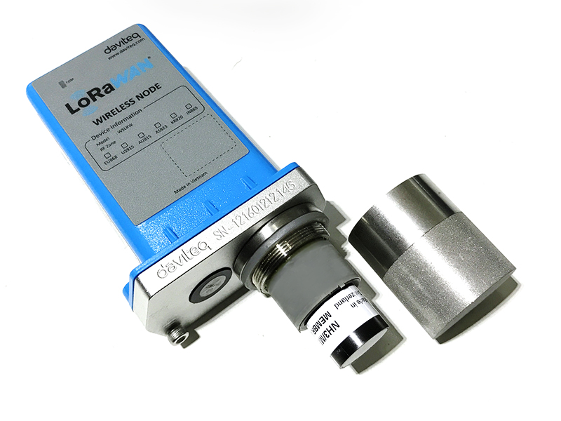
Step 1. Unscrew the housing
|
Step 2. Remove the filter
|
|
Step 3. Unplug the sensor module
|
Step 4. Plug the new sensor module into the PCB
|
|
Step 5. Insert the batteries and start calibrating the new sensor as per section 3.
|
Step 6. Place the filter back.
|
8. Default configuration
This NDIR gas sensor module has the default configuration. However, those parameters can be changed. The user can change the configuration on the wireless transmitter so that the complete sensor (transducer + wireless) delivers the proper output value. Below are some configuration parameters that store in the flash memory of the wireless transmitter.
| Description | Unit | Default | Format | Property | Comment |
| CONSTANT_A | 1 | Float | R/W |
Constant a for scaling measured value. This value would be changed after calibration. |
|
| CONSTANT_B | 0 | Float | R/W |
Constant b for scaling measured value. This value would be changed after calibration. |
|
| HIGH_CUT | 1E+09 | Float | R/W |
High cut value for scaled_value |
|
| LOW_CUT | 0 | Float | R/W |
Low cut value for scaled_value |
|
| SENSOR RESPONSE TIME | S | 100 | uint16 | R/W |
* Do not change this value |
| C_H_FACTOR | 4.4 | Float | R/W |
4.4 for CH4, 1.7 for C3H8 |
END.