USER GUIDE FOR LONG RANGE WIRELESS BRIDGES WS433-BL
| WS433-BL-MN-EN-01 |
DEC-2020 |
This document is applied for the following products
|
SKU |
WS433-BL |
HW Ver. |
2.4 |
FW Ver. |
2.0 |
|
Item Code |
WS433-BL-RS485-M2 |
Long Range Wireless Bridge, Master, RS485, external antenna 0 dbi, M12-Female connector, 4-pin, coding A |
|||
| WS433-BL-RS485-S2 |
Long Range Wireless Bridge, Slave, RS485, external antenna 0 dbi, M12-Female connector, 4-pin, coding A |
||||
1. Functions Change Log
| HW Ver. | FW Ver. | Release Date | Functions Change |
| 2.4 | 2.0 | JUL-2019 |
2. Introduction
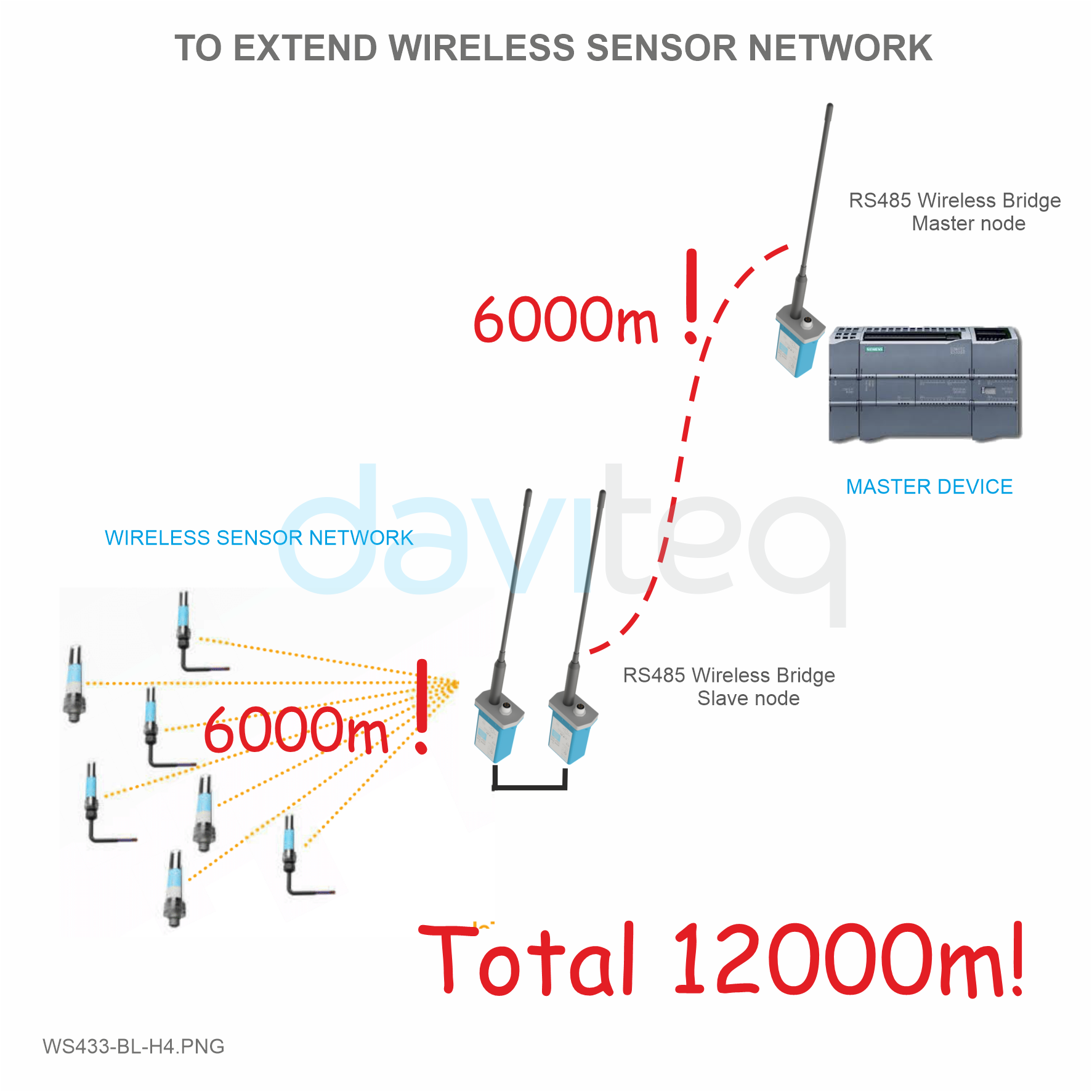
WS433-BL is a range of Sub-Ghz wireless bridges to replace the RS485 cable or network. This wireless technology will save time, labor cost & cable cost as well. LOS Distance is up to 6000m at baud rate 38400. Optional integrated IoT gateway (iConnector) allows easily configure & diagnose remotely or monitoring / controls via any IoT Platform as welll. The deployment of these wireless devices can be done in just 15 minutes!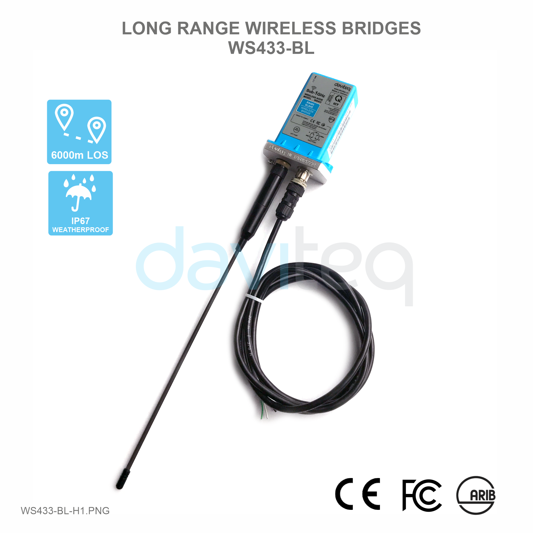
3. Specification
| Communication | RS485, RS232 (optional) |
| Wireless data rate | 50kbps (support baud rate 38400) |
| Tranmission distance | LOS 6000m @ 50 kpbs (lowest Antenna height is 4m) |
| Antenna | Standard external antenna -1.1 dBi for slave node, 3.0 dbi for master node (option 6 & 9 dbi) |
| Power supply | 7..48 Vdc @ 500mA max |
| Electrical connection | M12-female, 4-pin A-coding |
| RF frequency band | Free license ISM 433.92Mhz (for others 868, 915, 920Mhz, refer related datasheets) |
| Ready to comply | ETSI EN 300 220, EN 303 204 (Europe) FCC CFR47 Part15 (US), ARIB STD-T108 (Japan)** |
| Vietnam Type Approval Certification | QCVN 73:2013/BTTTT, QCVN 96:2015/BTTTT (DAVITEQ B00122019) |
| Data encryption | AES-128 |
| Ambient working temperature | -40oC..+85oC |
| Housing | Aluminum + Polycarbonate, IP67 |
| Mounting | Wall mounting holes |
| Product dimensions | H106xW73xD42 (excluded antenna) |
| Net weight | 190 grams |
| Packaging dimension | W160 x D150 x H100 mm |
| Gross weight | < 300 grams |
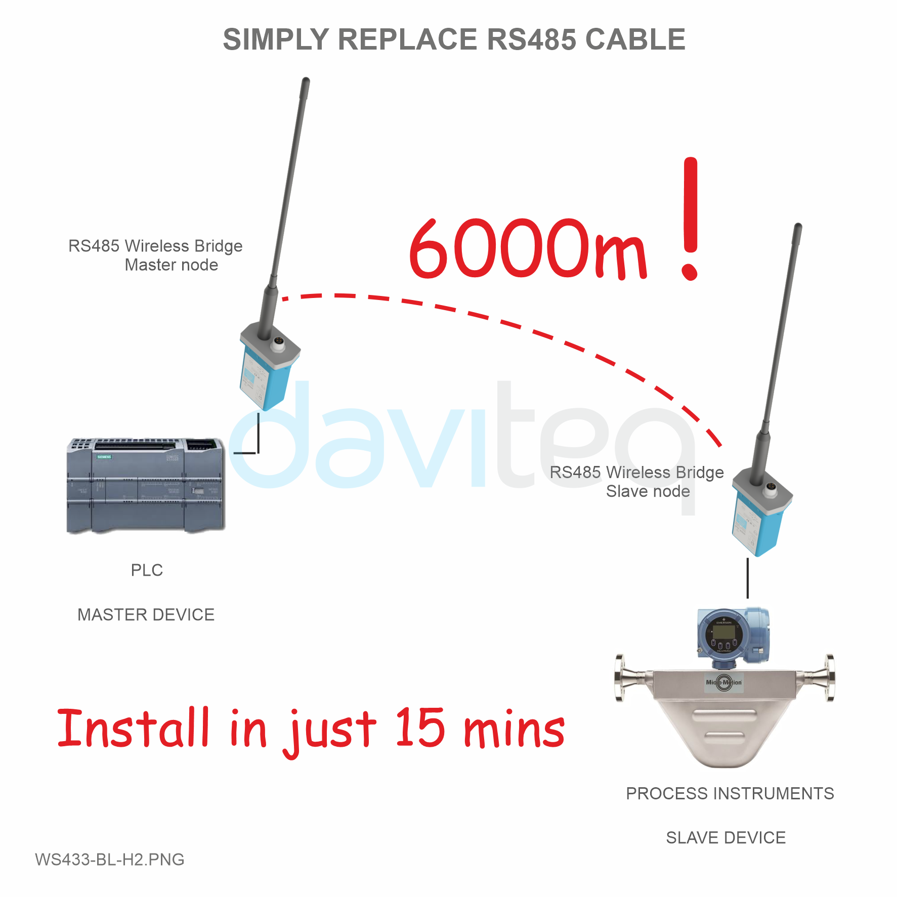
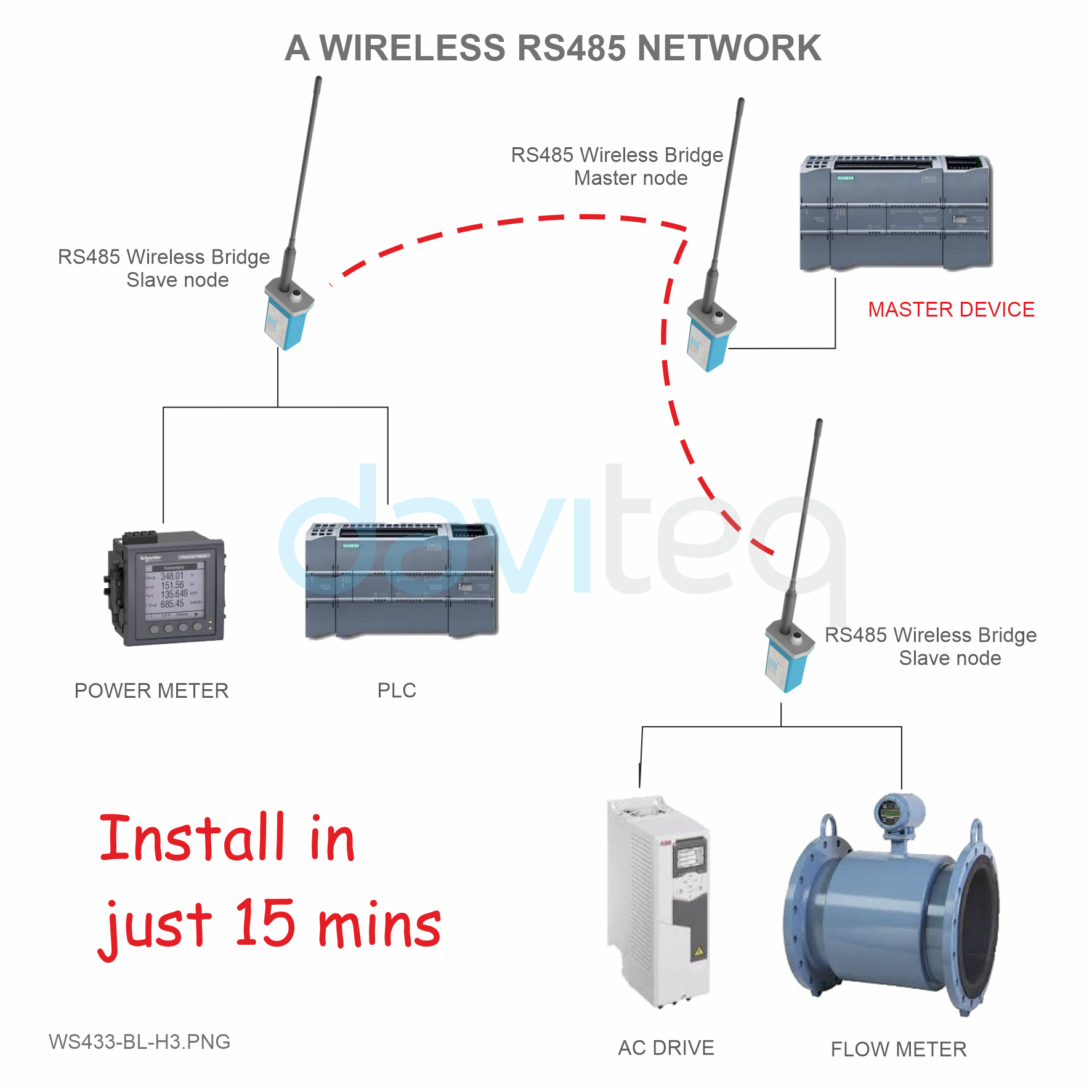
4. Applications
 |
 |
 |
|
5. Operation Principle
5.1 Add RS485 Wireless Bridge Slave into RS485 Wireless Bridge Master
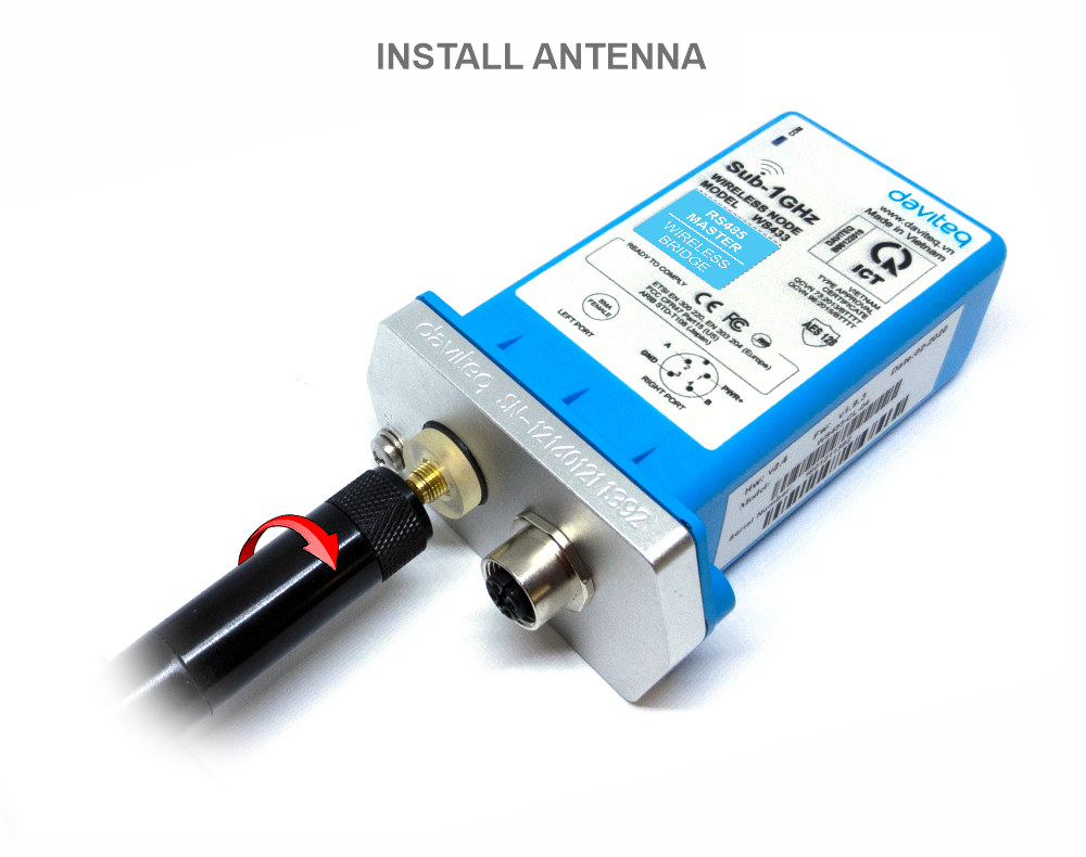
Step 1: Antenna settings for both master and slave
NOTE: Use your hand to tighten the antenna on the sensor, not using tools.
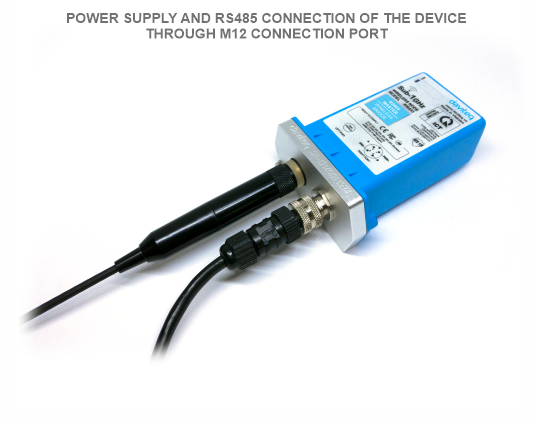
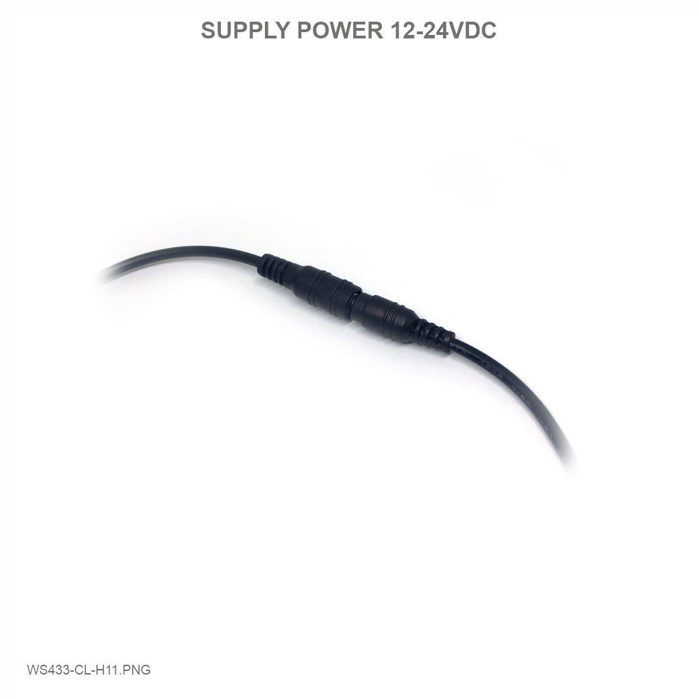
Step 2: 12-24VDC power supply for both slave and master via M12 connector
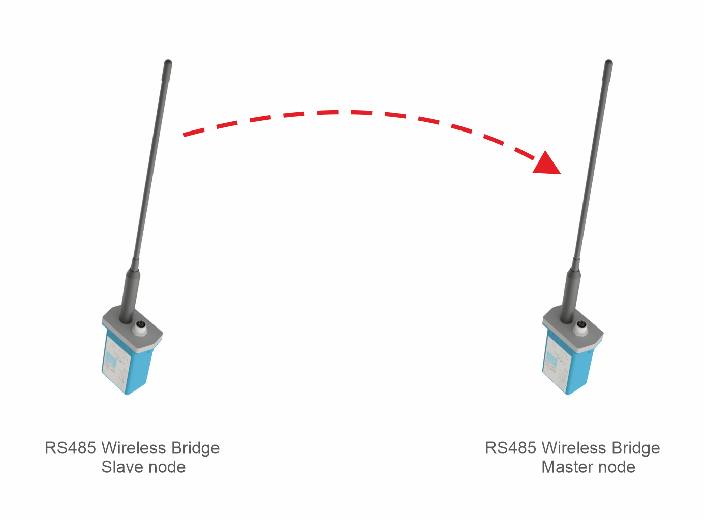
Step 3: Bring the antenna of Wireless bridge Slave closer to the antenna of Wireless bridge Master. If:
- Buzzer plays 1 peep sound, LED blink 1 time, that means registering Slave on Master successfully.
- Buzzer plays 2 peep sounds, LED blink 2 times, that this Wireless bridge Slave is already registered.
If you do not hear the "Peep" sound, please disconnect the power the Wireless bridge Slave, wait a few minute and try again.
Step 4: When you hear a beep indicating the successful registration of Slave to Master, you are ready to use the product.
WS433-BL replaces the traditional RS485 transmission line and wireless data transmission together. So after adding, the connection will be normal as traditional RS485 connection.
- WS433-BL Slave connects to the ModbusRTU device below (power meter, level meter,...);
- WS433-BL Master connects to the control device (PLC, IoT Gateway,..).
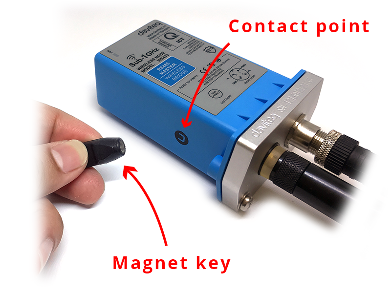
5.2 Hall sensor and button function
The Wireless Bridges are pre-configured, only use this feature when you really want to change the data rate.
Press and hold the push button or bring the magnet near the Hall sensor:
- For 2s => see the LED blink once or the buzzer will ring 1 Beep => Release the push button or Take the magnet out to set RF data rate RF 50 kbps
- For 5s => see the LED blink twice or the buzzer beep 2 Beep => release the push button or take the magnet out to set RF data rate RF 625 bps
- For 10s => see the LED blinking 3 times or the buzzer buzzes 3 Beep => release the push button or take the magnet to perform the User factory reset (User factory reset = reset frequency, RF transmit power, data rate, Slave ID, Modbus operating parameters, compare time for data status).
- If it takes more than 30 seconds, the button will be deactivated.

Default configuration:
- Frequency: 433.92 MHz
- RF transmit power: 15 dBm
- RF data rate: 50 kbps
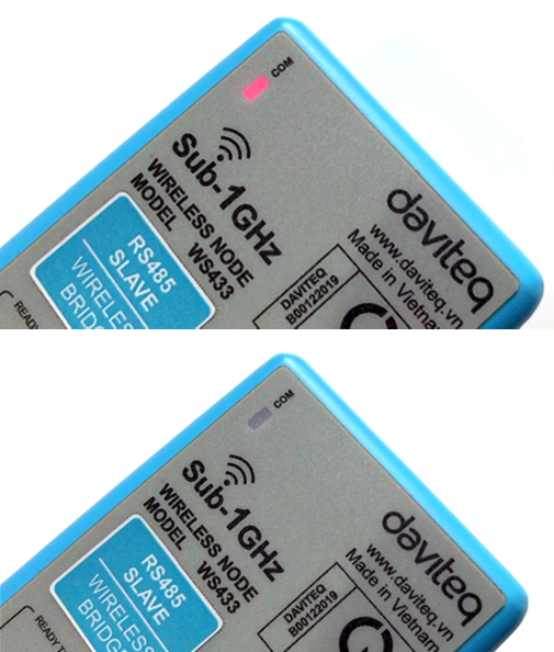
5.3 LED of WS433-BL
LED of WS433-BL will change state when RF data is received.
For example: when we read WS433-BL Slave data from WS433-BL Master, the LED on the Slave will change.
5.4 Checking connection with Modbus Tool
Default offline address:
The Wireless Bridge Master address is 200;
The Wireless Bridge Slave address is 201;
Other Modbus RTU devices have the address provided by the manufacturer.
First, you need to prepare

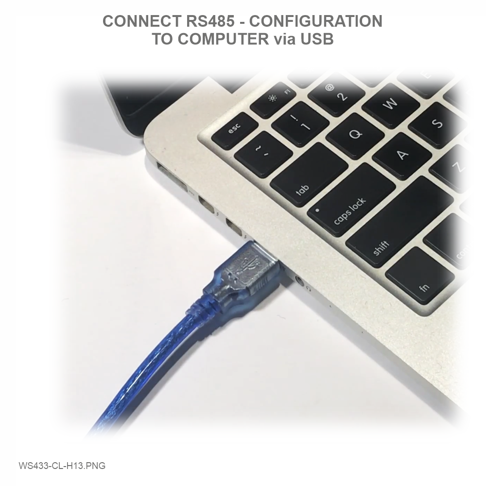
Step 1: Connect Antenna, RS485 - configuration cable and power supply the wireless bridge;
|
 |
 |
 |
Step 2: Open Modbus tool on PC
- You can download Daviteq Modbus Configuration Tool with the following link:
https://filerun.daviteq.com/wl/?id=BaX6RFlaEySKSYHX2j5nYHKBgeWckrox
Template File of WS433-BL Master: https://filerun.daviteq.com/wl/?id=cOS9c22bsg7PpRxNa1LAZZEVaZCuM3eq
Template File of WS433-BL Slave: https://filerun.daviteq.com/wl/?id=qBnH0kCshk4cRhawWGOauDAMDqHRhT4g
How to use the Modbus configuration software
- Unzip file and run file application "mb_master 1.1"

- Choose COM Port (the Port which is USB cable plugged in)
- Set the BaudRate: 9600, Parity: none
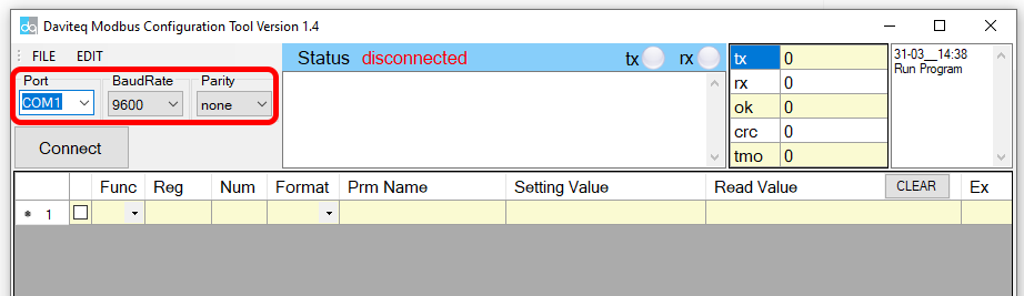
- Click “ Connect “ untill the Status displays “disconnected” to “connected“. It means the WS433-BL is being connected with computer;
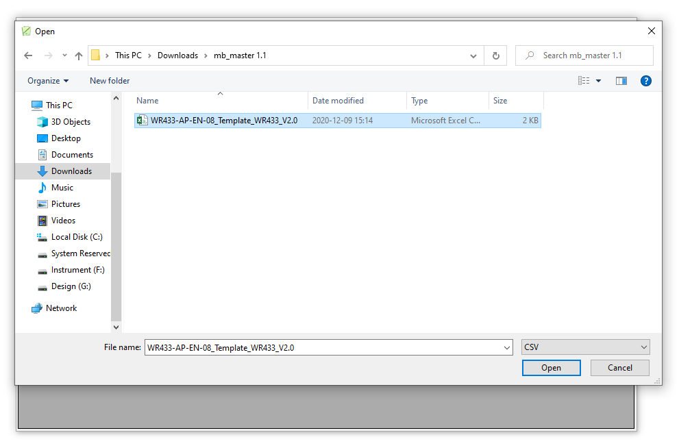
- Next, we need to import the configuration file for WS433-BL by importing the csv file: Go to MENU: FILE / Import New / => select the template file.
Please select the correct template to import into the tool
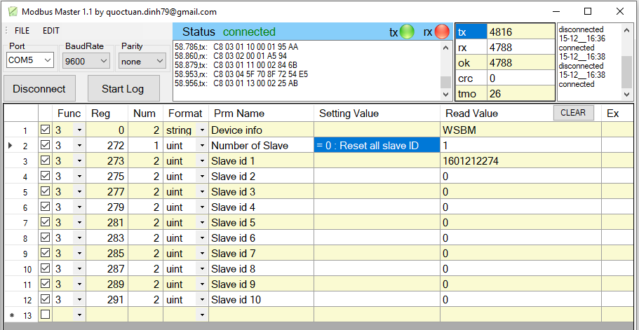
Step 3: We change the modbus address in column Slave (write in command 16 and read the value with command 3)
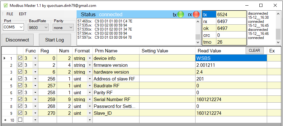
Example 1: We read the address of Wireless Bridge Master;
Example 2: We read the address of Wireless Bridge Slave;
6. Installation
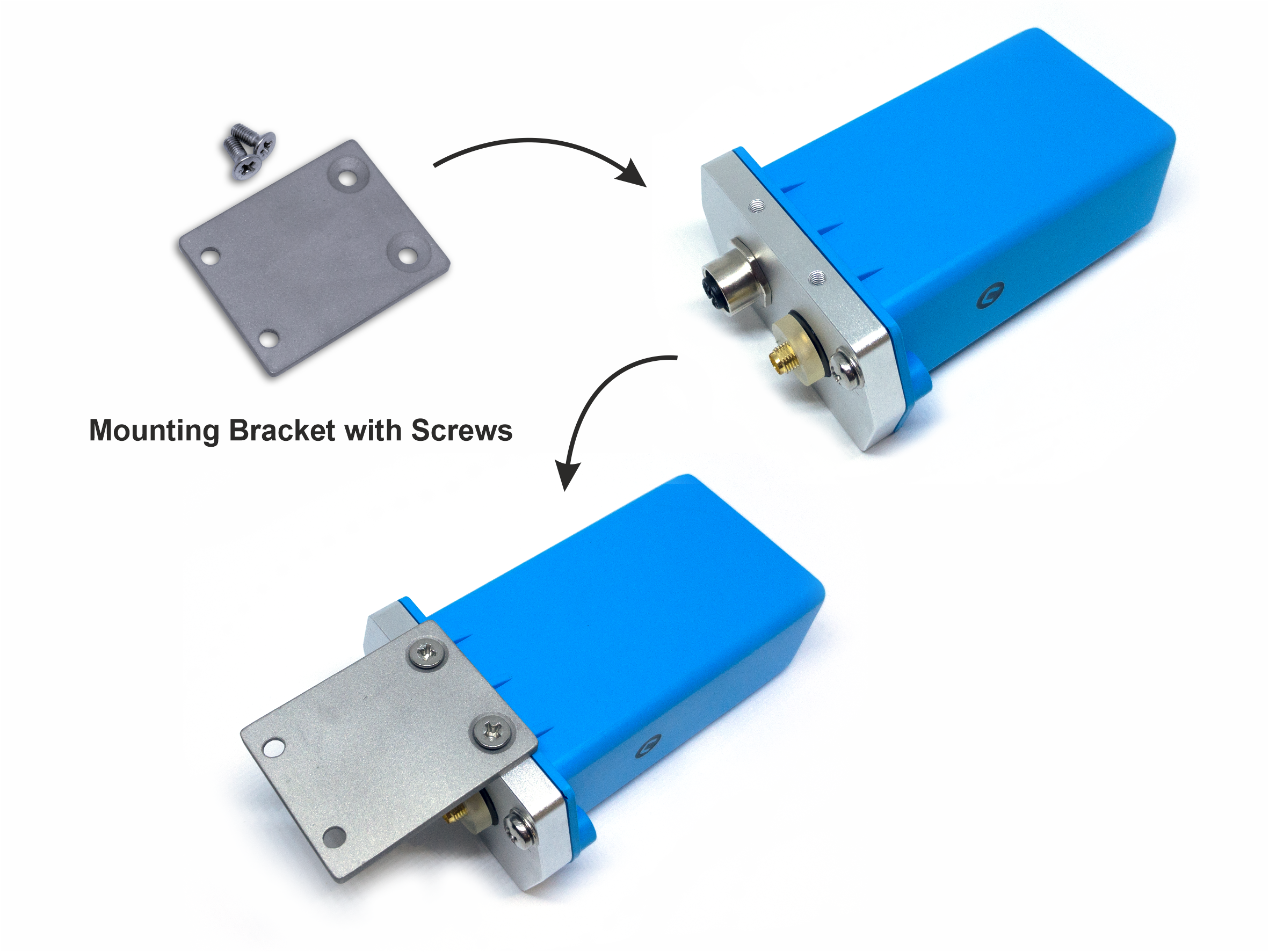
6.1 Mounting bracket installation
The mounting bracket is made from hard metallic material. Following to these steps as the below picture
6.2 IO Wiring
Please wiring as shown below:
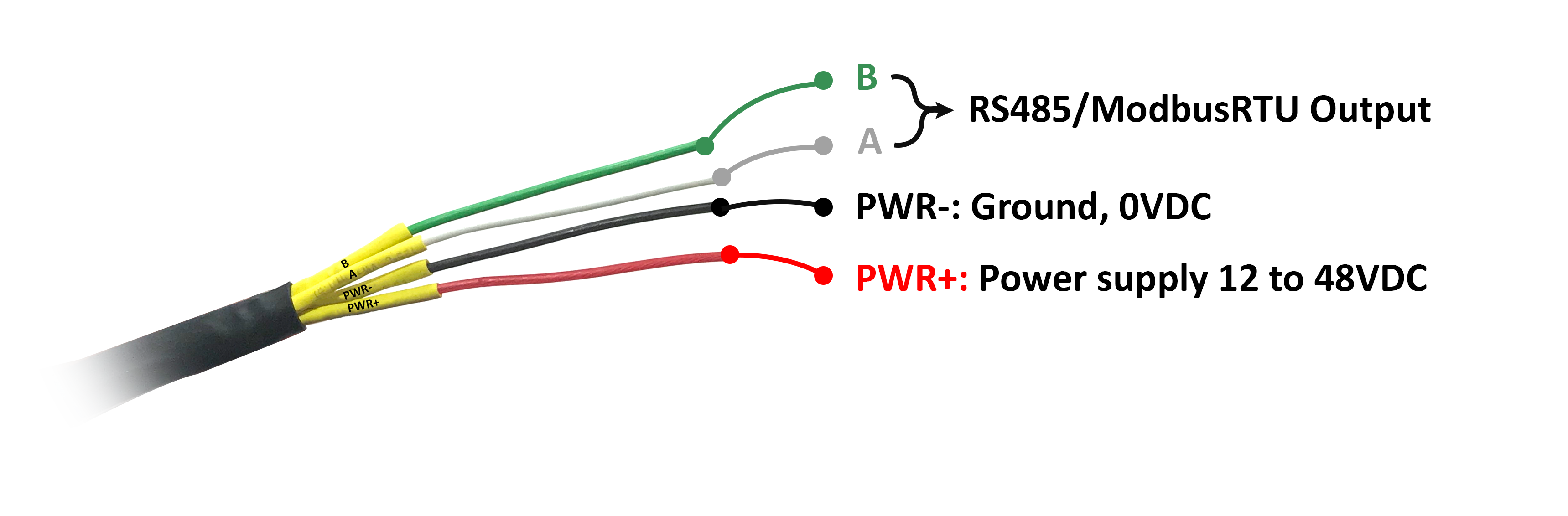
Each cable includes wires which are marked labels according to types of connection. (user should not cut these labels before installation to avoid confusing)
- Red: PWR+(12...48VDC)
- Black: PWR-(OVDC)
- Green: B
- White: A
Recommend to use 24VDC power.
The signal cable from sensor should be protected by corrugated hose or the Φ16 plastic tube, keep the cable avoid high temperature areas.
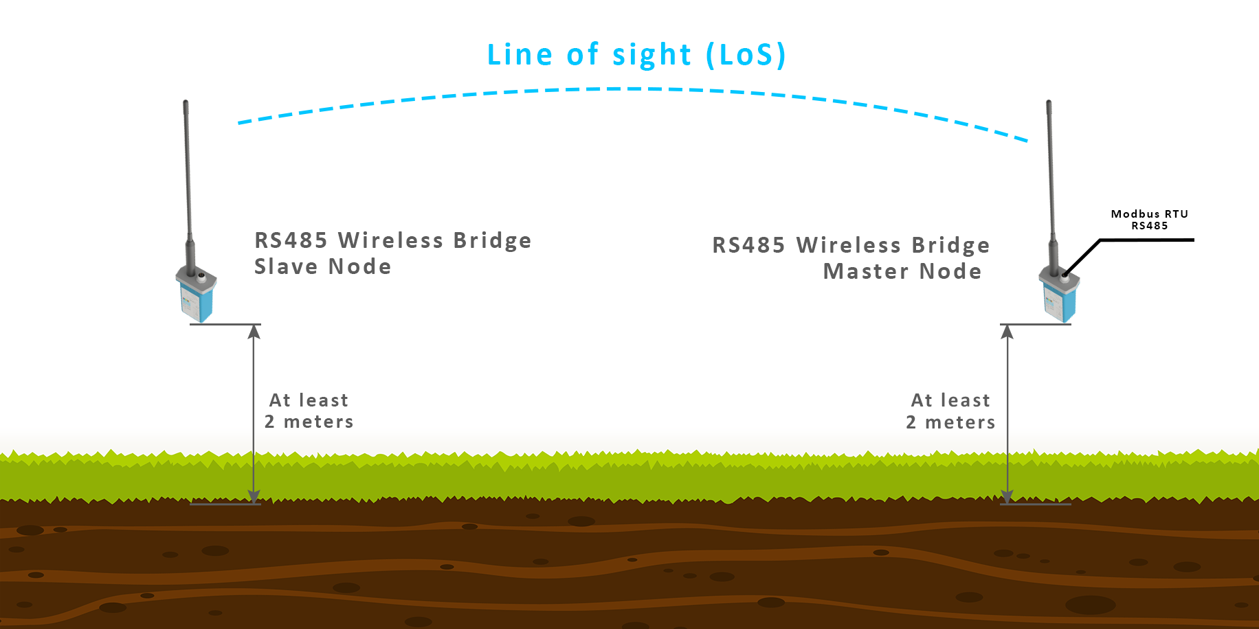
6.3 Installation location
The bracket will be fixed on the wall or material with a flat surface with 02 x M4 screws (supplied by the customer);
Please install the device at a height of 2 meters or less.
ATTENTION:
DO NOT install the Wireless bridge or its antenna inside a completed metallic box or housing, because the RF signal can not pass through the metallic wall. The housing is made from Non-metallic materials like plastic, glass, wood, leather, concrete, cement…is acceptable.
7. Troubleshooting
| No. | Phenomena | Reason | Solutions |
| 1 | Cannot read modbus |
|
|
| 2 | Cannot add slave into master |
|
|
8. Support contacts
|
Manufacturer
Daviteq Technologies Inc Email: info@daviteq.com | www.daviteq.com
|
Distributor in Australia and New Zealand
Templogger Pty Ltd Tel: 1800 LOGGER Email: contact@templogger.net |

No Comments