Manual for LoRaWAN Exd Design Gateway - GWLRWEX | FW9
I. QUICK GUIDE
This document is applied for the following products
|
SKU |
GWLRWEX |
|
SKU name |
LoRaWAN Exd Design Gateway |
|
Item Code
|
GWLRWEX-9; GWLRWEX-9-EG25-G; GWLRWEX-8; GWLRWEX-8-EG25-G |
1.1 Functions Change Log
| Firmware version
|
Hardware version |
Release Date |
Function Change |
|
9 |
2 | 28 Sep 26 |
1. Add Wi-Fi Configuration Mode (Access Point) on startup. 2. Change Packet Forwarder configuration. 3. Update LTE Watcher recovery mechanism. |
1.2 Introduction
The GWLRWEX is an Exd certified LoRaWAN® gateway designed for Oil & Gas, Petrochemical, and Energy industries. It supports up to 8 channels, handling high volumes of sensor data over ranges up to 10 km. With flexible connectivity options like Ethernet and LTE, and LoRa frequencies of 863∼870MHz and 902∼928MHz, it ensures seamless operation. Featuring built-in Network Server and Node-RED, it integrates directly with PLC, SCADA, or DCS systems. Its low-power design allows solar or battery operation, making it ideal for remote applications like wellhead monitoring, gas metering, and refinery facilities.
1.3 Application Notes
For Applications
Condition Based Monitoring, Energy Monitoring, Facility Monitoring, Gas Leakage Detection, Machine Health Monitoring, Production Monitoring, Temperature Monitoring, Vibration Monitoring
Notes
When selecting a LoRaWAN gateway, it is essential to choose the correct frequency band based on your region (e.g., 920–925 MHz or 863–870 MHz depending on local regulations). Ensure the gateway supports suitable network connectivity options such as Ethernet, Wi-Fi, or 4G/LTE, depending on the availability and reliability of internet access at the installation site. Also, consider whether the deployment is indoor or outdoor. The indoor gateways are compact and economy, while outdoor gateways should be weatherproof (e.g., IP67-rated) and capable of wider coverage. Choosing the right version ensures stable performance and long-term reliability.
1.4 What's in the Package?
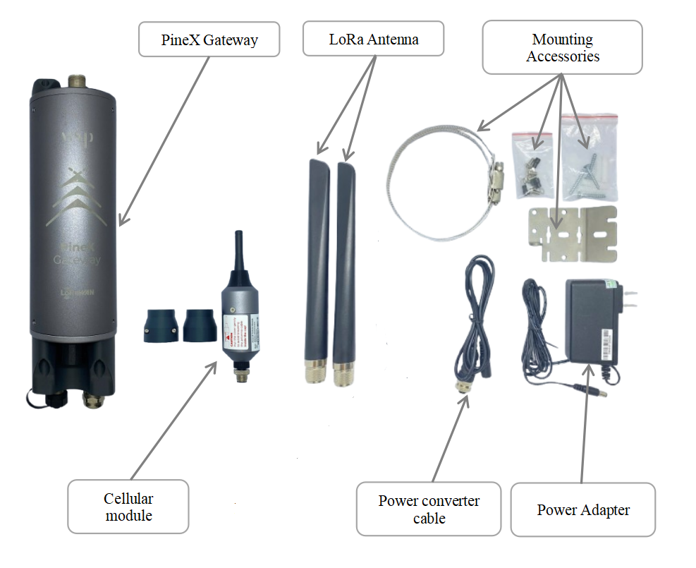
The package includes:
01 x LoraWAN Exd Design Gateway
02 x Lora Antenna
01 x Cellular module (optional)
01 x Power Adapter
01 x Converter cable
01 x Mounting Accessories
1.5 Product Overview
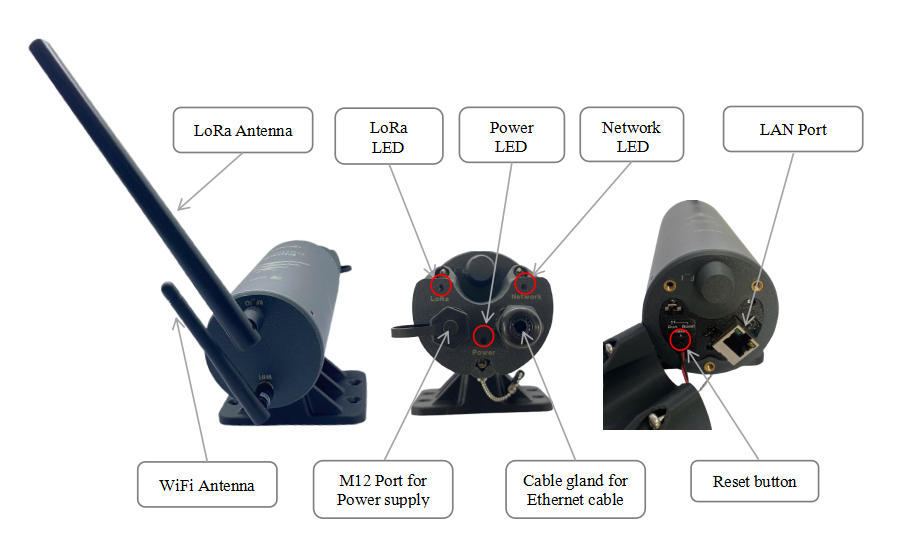
- LED Functions
| LED Functions | Constant | Flashing | Off |
| Power | Power On | None | OFF |
| Network | Initializing, High network traffic | Internet Available | Disconnected |
| LoRa | LoRa Working | Initializing | LoRa Not Working |
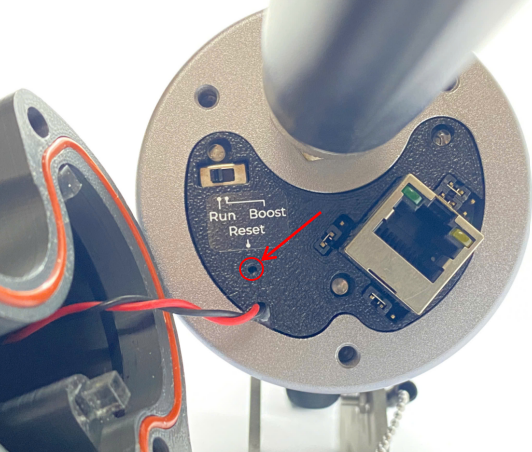
Some configuration such as Packet Forwarder settings, VPN settings, WAN settings will be restored to factory defaults when reset process completely taken.
Use a pointed stick to poke the button inside the hole and hold for 5 seconds. The gateway will automatically perform reset process. The whole process will take a few minutes.
Reset the device only when absolutely necessary
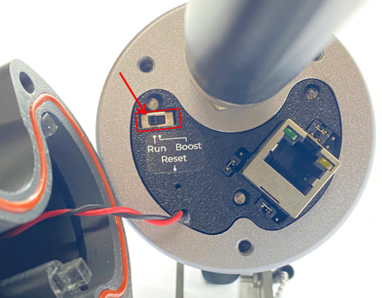
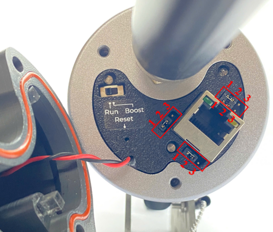
- Function switch
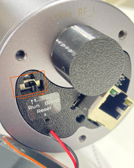
The switch have to be in Run position in normal operation. Boost mode uses for firmware update.
- Jumpers
There are four jumpers. Default position of four is connecting pin 1 and pin 2.
1.6 Power Supply
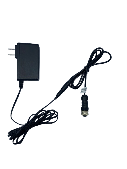
There are two ways to power the PineX Gateway. It is recommended to use the included power adapter ( 12VDC@2A) to power the gateway.
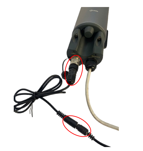
- Power the PineX gateway through the M12 Port
1.7 Guide for Quick Test
Startup the LoraWAN Gateway through the following steps
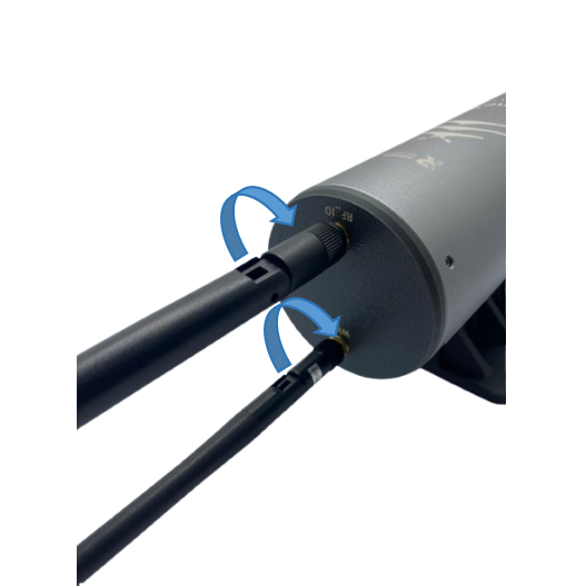
Step 1: Install the antenna of the LoRaWAN Gateway
Install the Lora antenna and WiFi antenna (optional) in the correct position. Make sure the antenna and Gateway are tightly connected.
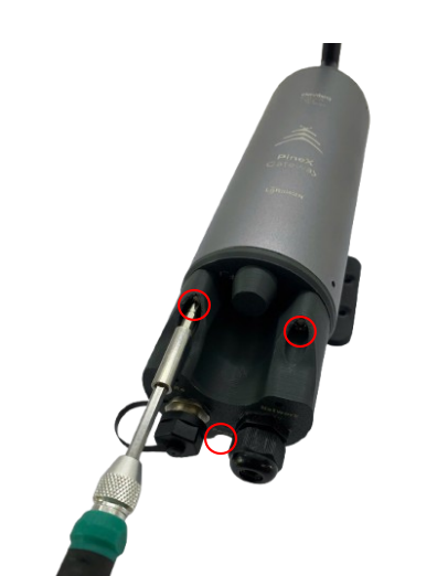
Step 2 :Use the screw driver to remove the three screws, then open the gateway cover.
Step 3: Connect the Ethernet cable to the Gateway
Connect the Ethernet cable into LAN port.
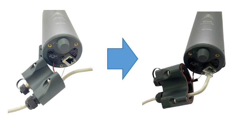
Step 4: Close the gateway's cover, then use the screw driver to lock the 3 screws.
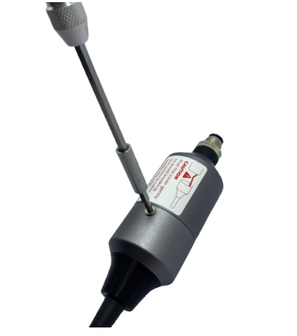
Step 5: Install the SIM card to Cellular module (optional)
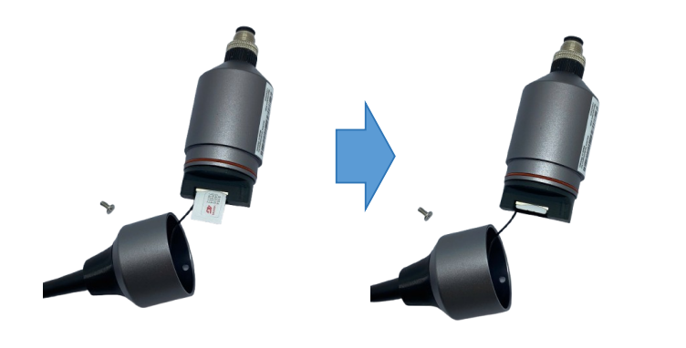
- Use the screw driver to remove the screw in the module, then carefully open the cap
- Insert the SIM card into the slot, pay attention to the direction of the Sim card
Step 6: Install the Cellular module to the gateway (optional)
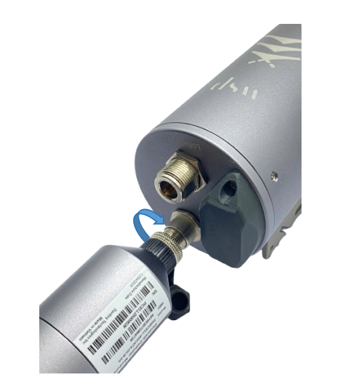
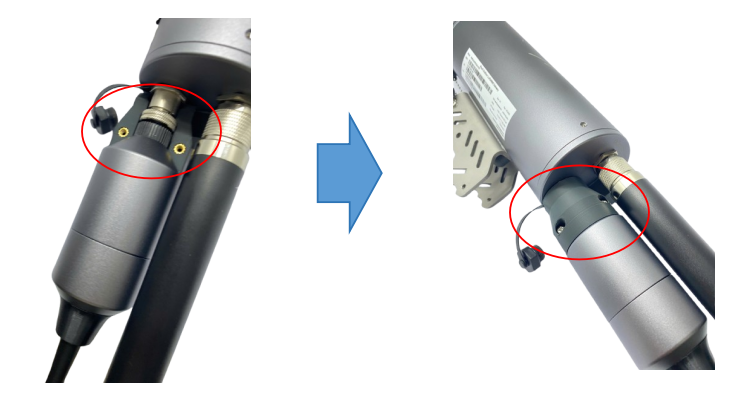
- Install the connection protection accessories
Step 7 : Power up the Gateway through M12 port
Step 8 : Access Gateway's GUI for configuration
There are two ways to access Gateway's GUI for configuration: via Wifi network or via Ethernet port
Access Gateway's GUI via Ethernet port
By default, the gateway is configured to use DHCP. Therefore, it must be connected to a network with an active DHCP server in order to access the Web GUI.
If the gateway is to be used in a static IP network without DHCP, it must firstly be connected to another active DHCP server to access the configuration interface to configure static IP for the gateway. Once the initial configuration is complete, the gateway can then be moved to the static IP network. Details of static IP configuration for the gateway are in sub-section of WAN SETTINGS in section of 2.2.6.2 Network WAN configuration
In some company with strict IT regulations, the gateway MAC address must be added to company network white list for proper connection.
- Use a computer to connect to the network that the gateway is connected. The computer can connect to that network via Ethernet.
- Use the IP scanning software to find the IP address of the gateway based on its Mac address that can be found on the back label.
Access this link to get a free IP scanning software on the internet
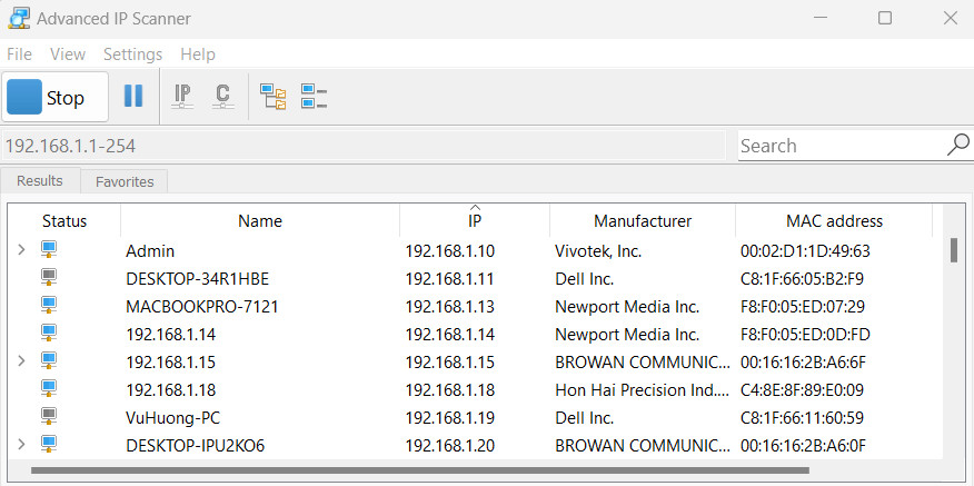
- Enter the IP address of the gateway in the web browser to access the configuration interface.
Must add port 4050 after the IP address. For example, If the IP address of the Gateway is 192.168.1.21 , you have to enter 192.168.1.21:4050 in web browser, then the GUI will be displayed.
The default username is admin and default password is public. Please check updated username and password on the gateway label.
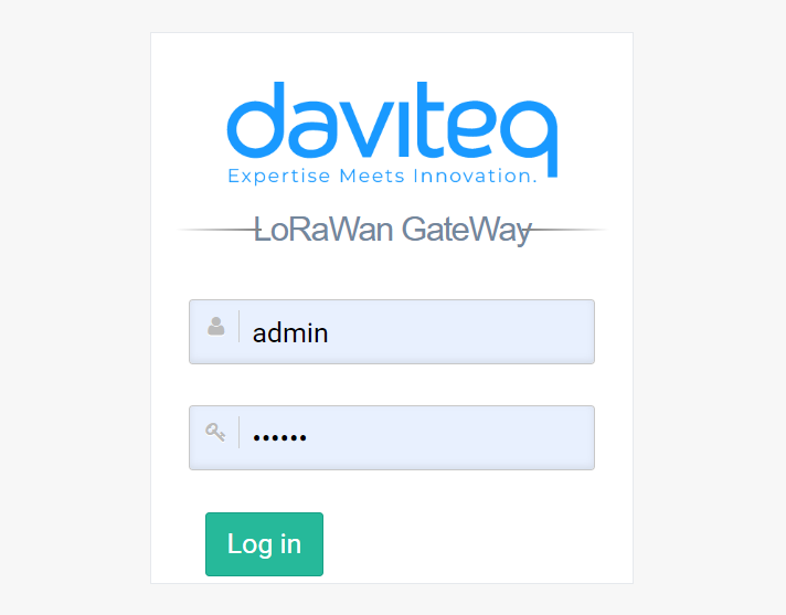
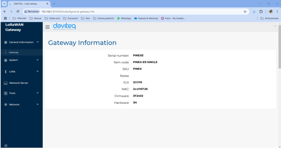
After login successfully, the general information of the gateway will be display at general information tab.
Access Gateway's GUI via gateway Wifi network
The gateway Wifi access point will be off automatically when user's PC has disconnect from this Wifi network
Step 9: Lora Settings
Package Forwarder
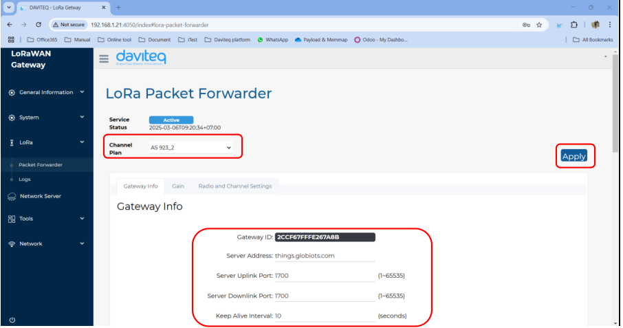
Select Packet Forwarder in the left menu, then choose Gateway Info. This page is for setting up the LoRa configuration including Channel Plan, Gateway ID, Server Address, Server Uplink Port, Server Downlink Port, Keep-Alive Interval, Statistics Display Interval, and Push Timeout
Need to properly configure the Server Address, Server Uplink Port, and Server Downlink Port fields. These information depend on the Network server.
Choose the channel plan for the gateway, then choose the Apply button at the bottom right to save the current configuration.
| Parameter name | Description | Default value |
| Channel Plan | The region refers to the specific geographical area where the gateway operates, following the LoRaWAN Regional Parameters defined by the LoRa Alliance | EU868 |
| Gateway ID | The Gateway ID (also known as DevEUI) is a unique identifier assigned to a LoRaWAN gateway. | Unique value |
| Server Address | The server address in a LoRaWAN gateway refers to the network server’s IP address or domain name that the gateway connects to for data transmission and management | localhost |
| Server Uplink Port | The server uplink port in a LoRaWAN gateway refers to the port number used to send uplink packets | 1680 |
| Server Downlink Port | The server downlink port in a LoRaWAN gateway is the port number used for receiving downlink packets | 1680 |
| Keep alive interval | The keep-alive interval is the time interval at which a LoRaWAN gateway sends periodic status messages (heartbeats) to the network server to indicate that it is active and connected. | 30 |
Watcher
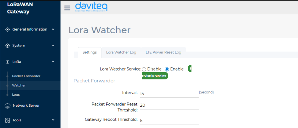
- Packet Forwarder:
- Interval: Interval for checking the system log to verify successful uplink to the network server.
- Packet Forwarder Reset Threshold: Number of consecutive uplink failures before resetting the packet forwarder
- Gateway Reboot Threshold: Number of packet forwarder resets before resetting the gateway.
Step 10: Network WAN configuration
This category shows current WAN settings. This category is further divided into three sectors: WAN Status, Data Statistics and WAN Settings.
-
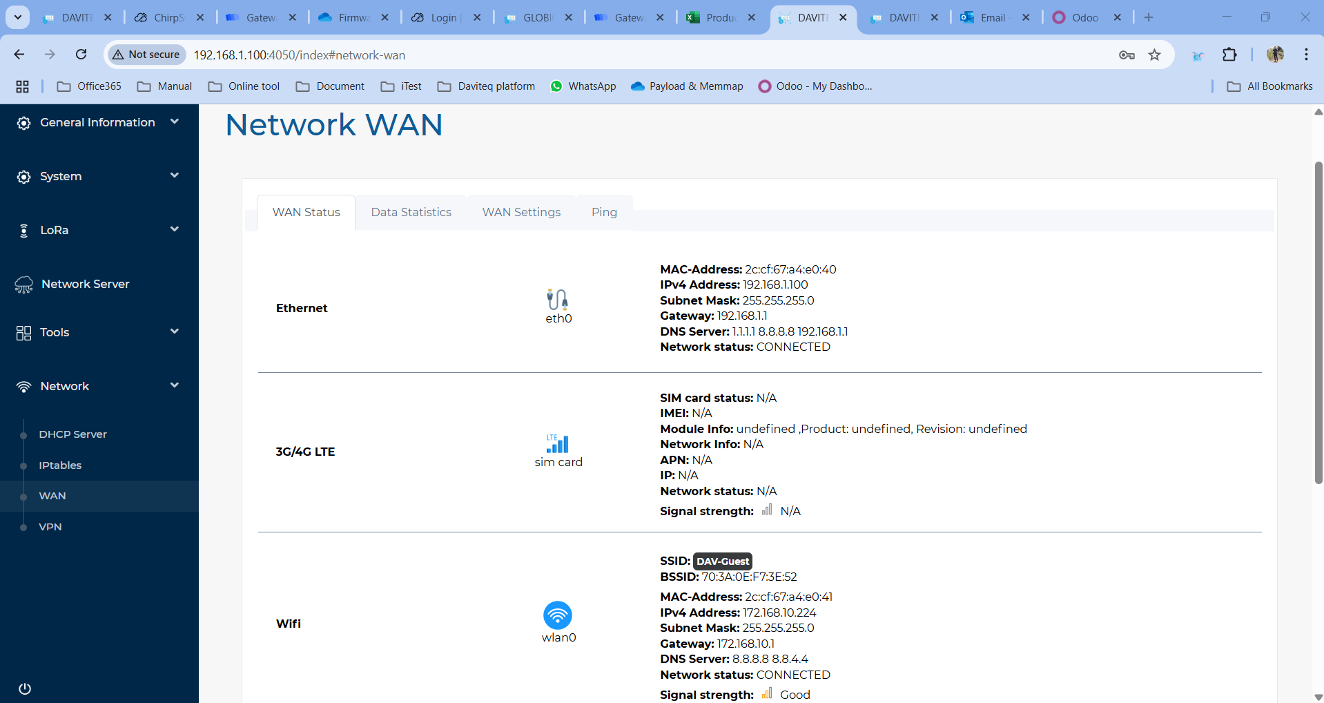
WAN Status
The current network status will be shown on this page.
-
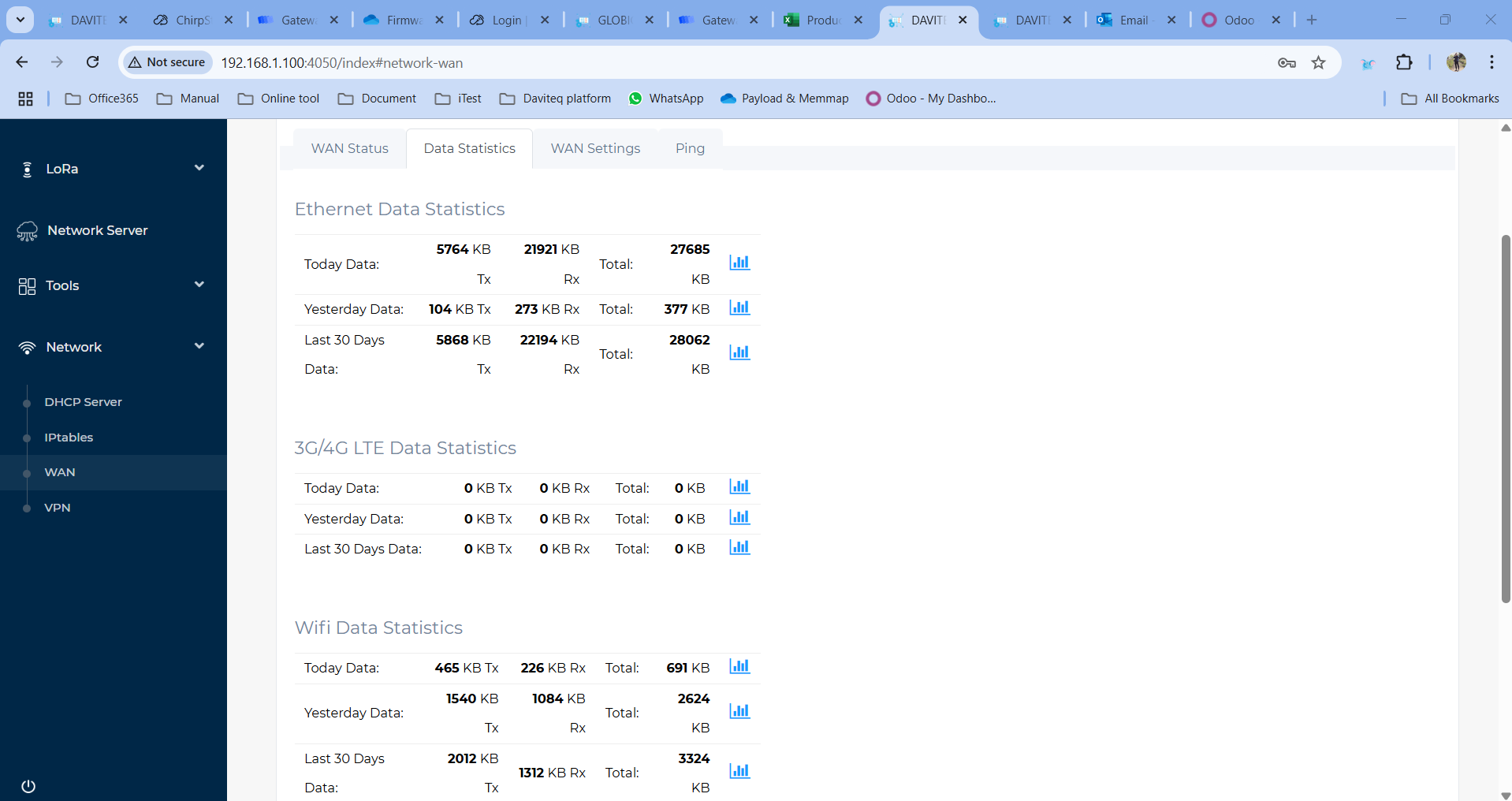
WAN Statistics
Statistics on the gateway's used data capacity are shown in this section
-
WAN Settings
Daviteq Gateway supports internet connectivity via both Ethernet , Wi-Fi (optional) or Cellular (optional).
The default Ethernet mode is DHCP.
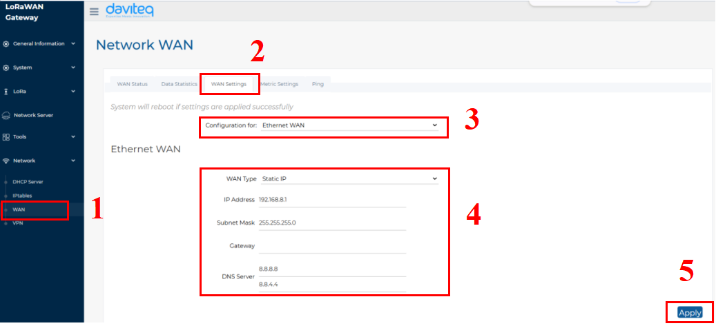
- Follow the steps below to set up the Ethernet network to static mode.
Step 1: In the Network section, select WAN.
Step 2: Click on the WAN Settings tab at the top.
Step 3: In the Configuration field, select Ethernet WAN
Step 4: Enter the Ethernet WAN information, including WAN Type, IP address, Subnet Mask, Gateway and DNS server
Step 5: Click the Apply button to save and apply the new configuration.
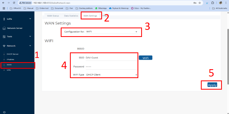
- Follow the steps below to set up the Wi-Fi network for the gateway:
Step 1: In the Network section, select WAN.
Step 2: Click on the WAN Settings tab at the top.
Step 3: In the Configuration field, select Wi-Fi.
Step 4: Enter the Wi-Fi information, including SSID (Wi-Fi name), Password, and Wi-Fi Type (default: DHCP Client).
Step 5: Click the Apply button to save and apply the new configuration.
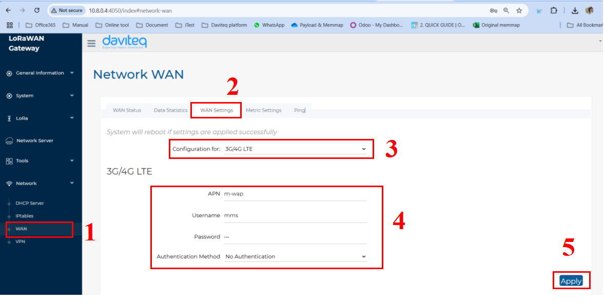
- Follow the steps below to set up the Cellular network for the gateway:
Step 1: In the Network section, select WAN.
Step 2: Click on the WAN Settings tab at the top.
Step 3: In the Configuration field, select 3G/4G LTE
Step 4: Enter the 3G/4G LTE information, including APN, Username, Password, and Authentication Method (base on the SIM card provider).
Step 5: Click the Apply button to save and apply the new configuration.
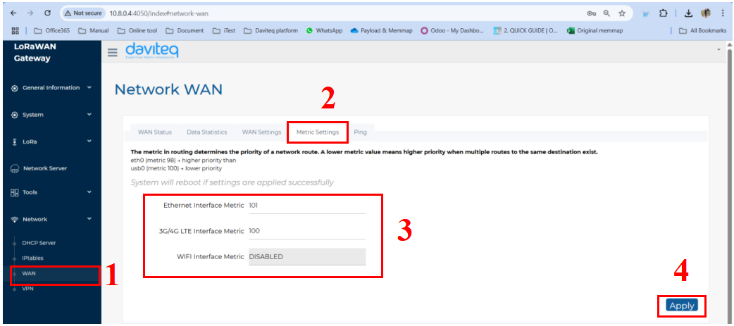
- Follow the steps below to set up network priority
The metric in routing determines the priority of a network route. A lower metric value means higher priority when multiple routes to the same destination exist. For example, 100 is higher priority than 101.
Step 1: In the Network section, select WAN.
Step 2: Click on the Metric settings tab at the top.
Step 3: Enter the the metric factor for available network.
Step 4: Click the Apply button to save and apply the new configuration.
1.8 Gateway Communication
1.8.1 Gateway communication to LoRaWAN device
1.8.2 Gateway communication to Network Server
1.8.2.1 Add the LoraWAN Gateway to Embedded Chirp Stack Network Server
Please follow instruction at link:
Instruction to configu... | Online Product Manuals & Datasheets
1.8.2.2 Add the LoraWAN Gateway to External LoRaWAN Network Server
To give an example, please follow the instructions in this link to add LoraWAN gateway to The things Stack network server
1.8.3 Activate and configure the embedded Node RED development tool
Prerequisite:
The Embedded Chirp Stack Network Server in the PINEX gateway must be active and configured properly to forward data to embedded Node RED development tool. Details to activate and configure embedded Chirp Stack are at the link: https://daviteq.com/en/manuals/books/manual-for-lorawan-sensor/page/instruction-to-configure-embedded-chirpstack-network-server-in-pinex-firmware-6
Please refer the below link for instruction to add the embedded Node RED development tool:
Instructions to config... | Online Product Manuals & Datasheets
To give an example, please follow the instructions in this link to add LoraWAN gateway to The things Stack network server
1.9 Default Communication
| Configuration | Default value |
| Time zone | UTC |
| LoRaWAN Frequency plan | EU868 |
| Network Server host | localhost |
| NS uplink port | 1700 |
| NS downlink port | 1700 |
| Network Server Settings description | OFF |
| NS integration descriptions | OFF |
| NodeRED Settings descriptions | OFF |
| IP forwarding | OFF |
| WAN Ethernet Settings | DHCP Client |
| VPN setting | OFF |
| Ethernet Interface Metric | 100 |
| 3G/4G LTE Interface Metric | 101 |
| WIFI Interface Metric | DISABLED |
| Lora Watcher Service | ENABLE |
| Packet Forwarder Interval | 15 |
| Packet Forwarder Reset Threshold | 20 |
| Gateway Reboot Threshold | 5 |
1.10 Installation and Wiring
-
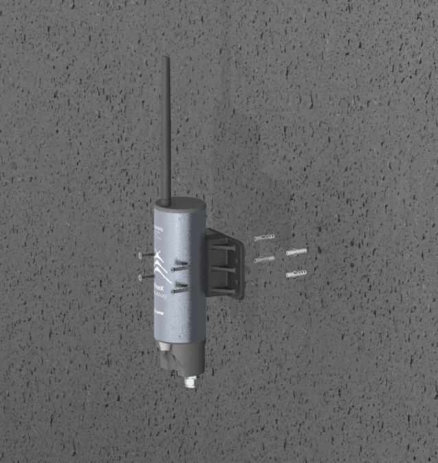
Economy version
Step 1: Select the installation location. The surface must be flat.
Step 2: Based on the dimensions of the gateway's base, drill four holes into the wall. Then, insert wall anchors into the drilled holes.
Step 3: Use screws to secure the gateway onto the drilled surface.
-
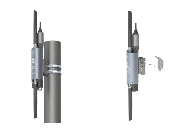
Advanced version
There are two methods for mounting the gateway
1. Mount the gateway to the steel pole with a hose clamp
2. Attach the bracket to the wall, then mount the gateway on the bracket.
II. MAINTENANCE
2.1 Maintenance
There is no requirement for maintenance of the Hardware of LoRaWAN Gateway.
2.2 Troubleshooting
| Problem | Possible causes | Solution |
| The Ethernet port's LED is not lighting up | Gateway is in boost mode |
Turn off the power supply, wait until all the gateway's LEDs are off, then change the switch from Boost to Run. After that, Power on the gateway. |
| Can not scan the gateway's IP address |
1. The computer and the gateway are not on the same network 3. The gateway was configured to use static IP mode |
1. Check network of computer and gateway. 2. Use another active DHCP server network to access the configuration interface. 3. Press & hold the reset button within 5 seconds, then wait for 5 minutes before trying again. |
| The gateway is not online on Network Server | Wrong configuration | Check the Package Forwarder configuration on the gateway and gateway register configuration on Network Server. |
III. ADVANCE GUIDE
3.1 Operation Principle
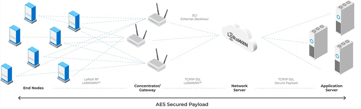
A LoRaWAN gateway functions as a transparent bridge between LoRa end devices and the LoRaWAN network server. It receives uplink packets from end devices via LoRa radio signals and forwards them to the network server over an IP-based backhaul (e.g., Ethernet, Wi-Fi, or cellular).
The gateway also receives downlink messages from the network server and transmits them to the appropriate end devices. It does not process or modify the payload data, ensuring secure and efficient communication between devices and the server.
3.2 Firmware update
3.2.1 Preparation
- Prepare a Windows PC.
- Prepare a USB-C cable for connecting the PC and the gateway.
- Download and unzip the firmware file
3.2.2 Download and Install Software
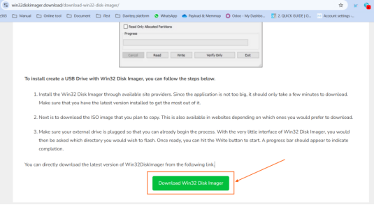
Download & Install Win32DiskImage from the link
Download & Install Raspberry USB Boot
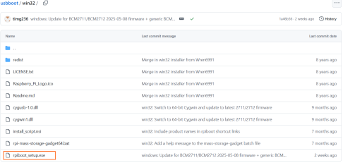
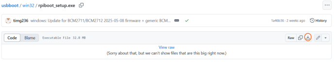
Visit the link and download rpiboot_setup.exe. Then, install Raspberry USB Boot in the PC
 3.2.3 Flashing Firmware to PineX Gateway
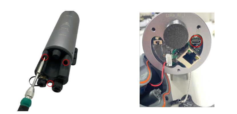
Step 1: Make sure the gateway is completely powered off (all three LEDs are off).Use a screwdriver to remove the three screws and open the gateway cover. Then, remove the plastic cover to access the USB-C port.
Step 2: Change the switch mode from Run to Boost as shown in the picture.
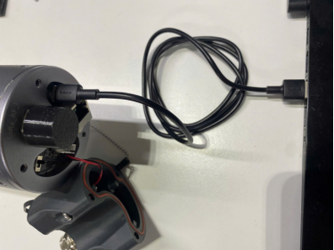
Step 3: Power on the gateway and wait for about 15 seconds. Then, connect the gateway to the PC via the USB-C cable.
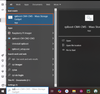
Step 4: Open rpiboot-CM4-CM5-Mass Storage Gadget.
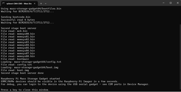
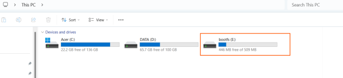
Open This PC on the PC and check whether a new drive named "bootfs" appears.
If "bootfs" appears as shown in the image below, the connection is successful.
If "bootfs" does not appear, go back and repeat the process from Step 1.
Take note of the drive letter assigned to "bootfs" — for example, Drive E:
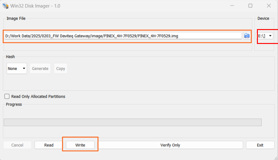
Step 5: Open Win32DiskImage software. Browse to the firmware file and select correct Device (the drive letter assigned to "bootfs" in step 4). Then click the Write button to flash the firmware to the gateway.
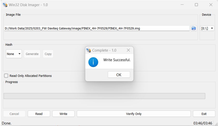
Wait a few minutes until a "Write successful" message is displayed. This means the firmware flashing process has completed successfully.
3.3 Connect directly from window PC to gateway through ethernet cable for configuration
3.3.1 PREPARATION
Hareware
- A Daviteq gateway
- A window laptop
- A USB-to-LAN adapter ( if the laptop does not have ethernet port)
- A traight ethernet cable
Software
Download and Install Tftdp64 software (attached file)
3.3.2 DETAILED INSTRUCTIONS
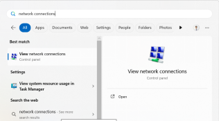
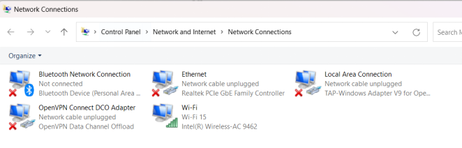
Step 1: Type “Network Connections” in the search bar, then select “View network connections.”
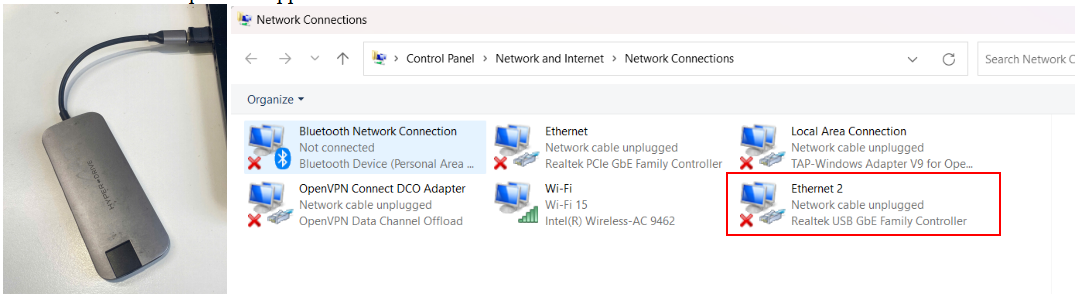
Step 2: Plug the USB-to-LAN adapter into the laptop. Wait for a few seconds, and the Ethernet connection of the adapter will appear.
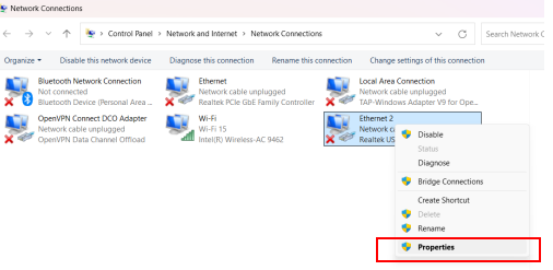
Step 3: Right click the Ethernet connection of the adapter, then select Properties
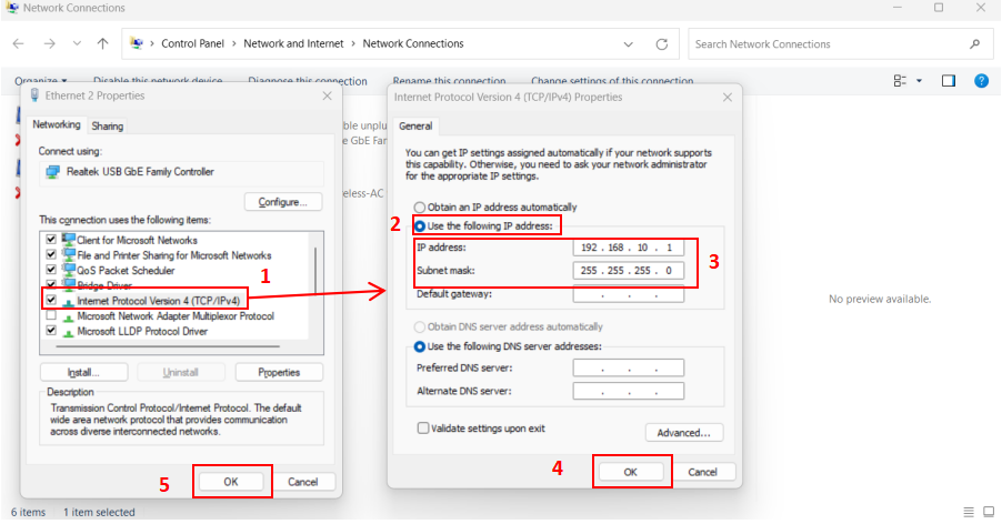
Step 4: In the Networking tab, select Internet Protocol Version 4(TCP/IPv4).
Then, select Use the following IP address and input the imformation as shown in the picture below
IP address : 192.168.10.1
Subnet mask: 255.255.255.0
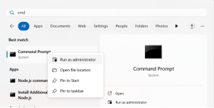
Step 5: Run Command Prompt as administrator
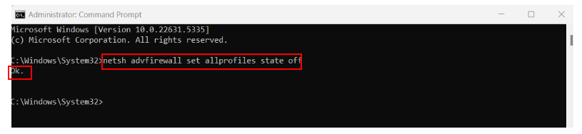
Copy and paste command below to the Command Promt to temporarily turn off the Firewall
netsh advfirewall set allprofiles state off
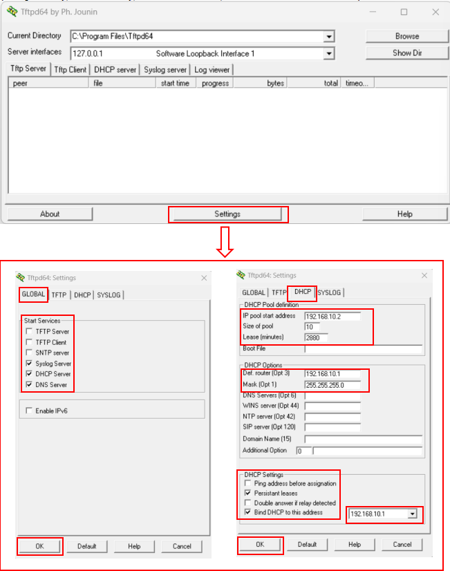
Step 6: Open the Tftpd64 Software, click the Settings button, then configure it as shown in the pictures below. After that, click OK to save the new settings.
(Only change the settings in the red box, leave the rest as default)
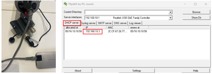
Step 7: Power on the gateway, then connect the Ethernet cabble from the gateway to the laptop through the adapter. Wait for a few seconds, the IP address of the gateway will be displayed in DHCP server tab of the Tftpd64 software
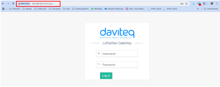
Step 8: Access the gateway’s GUI via the IP address and port 4050 (e.g., 192.168.10.3:4050).
If the web browser displays as shown in the image below, it means you have successfully accessed the gateway. Next, refer to the user guide to configure the Wi-Fi and the LoRaWAN Package Forwarder for the gateway.
Step 9:After finishing the configuration, please turn the firewall back on for your computer.
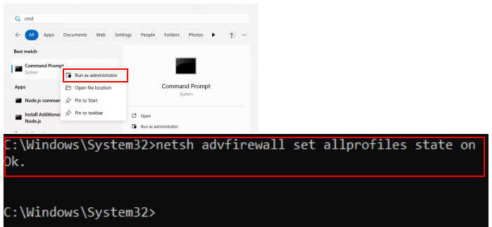
Run Command Prompt as administrator, then copy and paste the command below to the Command Promt
netsh advfirewall set allprofiles state on
IV. PRODUCT SPECIFICATIONS
| LoRaWAN Specification | LoRaWAN 1.0.3, support for LoRaWAN Class A, Class C protocols |
| Frequency Band | Select 863∼870MHz or 902∼928MHz |
| Number of Channels | Up to 8 concurrent channels for LoRa transmission |
| LoRa Transmit Power | 0.5W (up to 27 dBm) |
| LoRa Receive Sensitivity | Down to -139dBm@SF12, BW 125 kHz. |
| Features | Dynamic data-rate adaptation (ADR) |
| Software | LoRa Package forwarder, Chirpstack, OpenVPN, Node-red, SSH root access |
| COMMUNICATION | |
| Standard communication | Ethernet 100Mbps, via outdoor RJ45 connector |
| Optional 4G LTE | LTE Cat 4, Global bands |
| LTE FDD: B1, B2, B3, B4, B5, B7, B8, B12, B13, B18, B19, B20, B25, B26, B28 | |
| LTE TDD: B38, B39, B40, B41 | |
| UMTS: B1, B2, B4, B5, B6, B8, B19 | |
| GSM: B2, B3, B5, B8 | |
| Antenna Type | 1 x external LoRa antenna via N-type connector, 1 x External antenna for LTE via SMA connector |
| Housinng | Aluminum alloy, powder coated, IP67, Wall mount installation |
| Certified Ex d | FTZU 03 ATEX 0207U, TÜV CY 18 ATEX 0206158 X, and IECEx FTZU 12.0017U, IECEx MSC 19.0001X |
| Hazard Protection Label | ATEX II 2G Ex db IIC T5/T6 Gb and ATEX II 2D Ex tb IIIC T100/T85℃ Db |
| Standard | IEC-EN60079-0 IEC-EN60079-1 IEC-EN60079-31 |
| Areas of application | Zones 1 & 2 gas hazardous areas, Zones 21 & 22 hazardous areas containing flammable dust |
| Working temperature | -40 ∼ 85℃ |
| Size | Net weight | H202xW126xD128 (not including antenna)/ ≈1500g |
V. WARRANTY & SUPPORT
Below terms and conditions are applied for products manufactured and supplied by Daviteq Technologies Inc.
5.1 Warranty
-
Free Warranty Conditions:
- The manufacturer undertakes to guarantee within 12 months from shipment date.
- Product failed due to defects in material or workmanship.
- Serial number, label, warranty stamp remains intact (not purged, detected, edited, scraped, tore, blurry, spotty, or pasted on top by certain items).
- During the warranty period, if any problem of damage occurs due to technical manufacturing, please notify our Support Center for free warranty consultancy. Unauthorized treatments and modifications are not allowed.
- Product failed due to the defects from the manufacturer, depending on the actual situation, Daviteq will consider replacement or repairs.
Note: One way was shipping costs to the Return center shall be paid by Customers.
-
Paid Warranty
- The warranty period has expired.
- The product is not manufactured by Daviteq.
- Product failed due to damage caused by disasters such as fire, flood, lightning or explosion, etc.
- Product damaged during shipment.
- Product damaged due to faulty installation, usage, or power supply.
- Product damage caused by the customer.
- Product rusted, stained by effects of the environment or due to vandalism, liquid (acids, chemicals, etc.)
- Product damage is caused by unauthorized treatments and modifications.
Notes:
* Customers will be subjected to all repairing expenses and 2-way shipping costs.
* If arises disagreement with the company's determining faults, both parties will have a third party inspection appraise such damage and its decision be and is the final decision.
5.2 Support
If you need our support for Daviteq device's installation, configuration, test, and decode, please email us at: support@daviteq.com OR input support request at link: https://forms.office.com/r/XWHbYG7yy7 .Our support engineer will contact you via email or the support ticket system.