OPERATION INSTRUCTION
OPERATION INSTRUCTION FOR RMC SYSTEM-AEON DELIGHT
1. Overview of the Operating Principle
- The LRW-DI sensor is connected to the contacts that output the alarm signals.
- When the LRW-DI sensor receives an alarm signal from the field devices, it will send a data packet to the Gateway via a wireless signal. The Gateway will then forward it to the server through the internet connection (4G SIM).
- The supervisor will observe the alarm signal on the software.

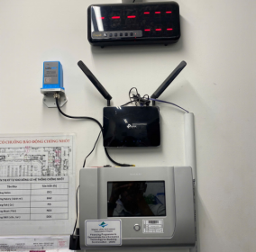
2. Overview of the System Hardware
- Main device list
|
No. |
Item code |
Description |
|
1 |
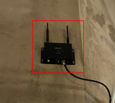
GWIND-8 |
GATEWAY LORAWAN - INDOOR, POE |
|
2 |
BP-11V-28AH-01 |
Battery Pack 11V 28AH |
|
3 |
WSLRW-DI-12 |
LORAWAN NODE WITH DIGITAL INPUT |
|
4 |
CONVT-ACDC-OPTO-01 |
Converter for AC100-220VAC and 10-30VDC to open collector |
|
5 |
L91-ENERGIZER |
BATTERY AA ENERGIZER LITHIUM |
|
6 |
SIM3G-BIGDATA |
SIM3G-BIGDATA |
3. Software Features Guide
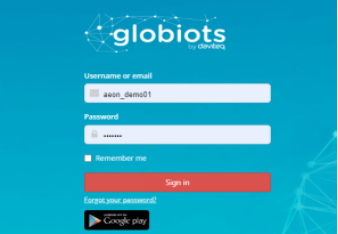
3.1. Login Instructions
Step 1: Access the software via the link: https://vizuo.globiots.com
Step 2: Log in with the account:
3.2. Main Monitoring Dashboard
After successfully logging into the software, navigate to Management => Dashboard => AEON-DELIGHT-RV00002 to access the main monitoring interface.
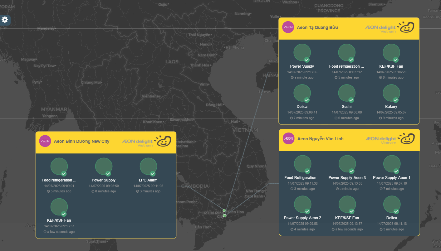
Feature Description:
- Each dot on the map represents the status of one site
- Normal: Green
- Alarm: Flashing Red
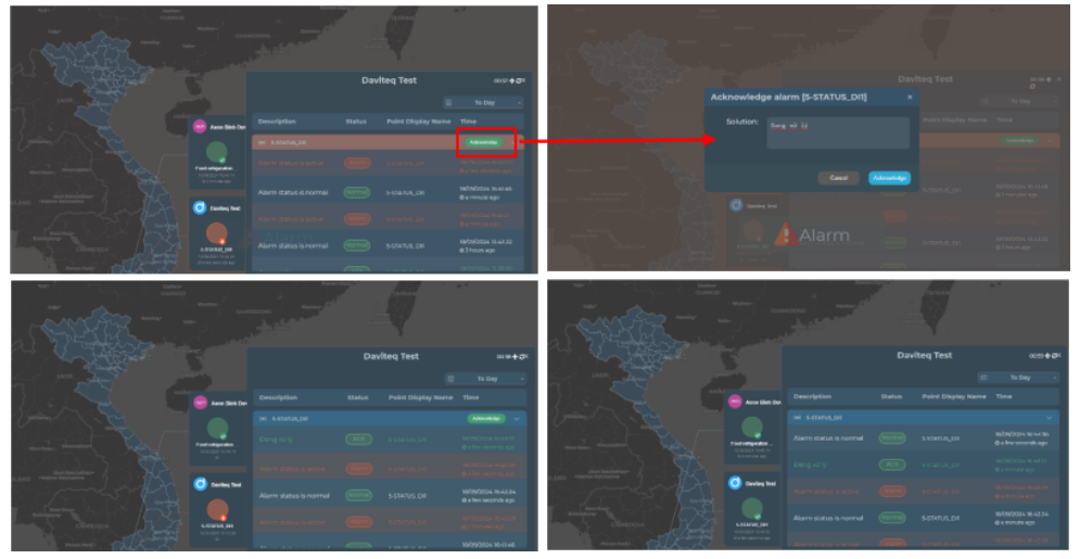
- Each site will have a alarm information table that includes the alarm Each circle with the corresponding name below indicates the status of that point.
- Normal: Green
- Alarm: Red
- When clicking on the alarm information table, a history of alarms will be displayed. This table contains the historical alarm information for all points in the corresponding site, allowing for time selection to retrieve data.
- When a alarm occurs, the site dot will flash red, and the circle of the alarm point will also turn red. An alarm will sound through the computer speaker. Users can acknowledge the alarm to silence the sound, but the dot and circle will still display red.
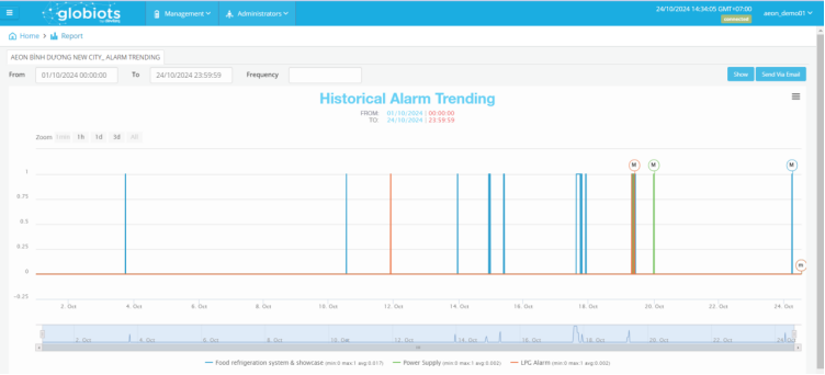
3.3. Instructions for Reports
The vertical axis represents the status of the signal (1 = Alarm; 0 = Normal). The horizontal axis is the timeline.
Step 4: Click to the symbol at the top right corner, select Export to CSV to export the data as a .csv file
3.4. Alarm Management
The feature allows for retrieving the historical alarm data of each monitoring point. The retrieval time is optional and allows exporting the report as a .xls file.

Step 4: Click the Export button to export the file in .xls format.
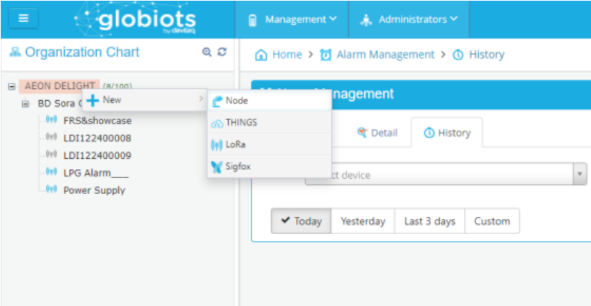
3.5. Other Features
3.5.1 Device management: allows to expand additional sites (Nodes) and monitoring points (LoRa).
3.5.2. User management
User is created by following steps:
- In Home screen, click menu Administrators → select sub-menu User Management
- In screen of user list, click button “Add user” to add new user.
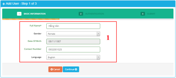
- Enter basic information into panel (1).
- Click button “Continue” to go to step 2.
- After click button “Continue”, screen of step 2 should appear:
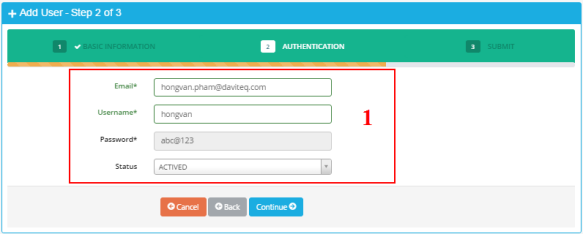
- Enter information for user to sign-in into panel (1):
Email: enter email address. Email is unique.
Username: enter username for sign in. Username is unique. Username has at least 6 characters.
Password: default password is “abc@123”. User must change password when user sign in in the first time.
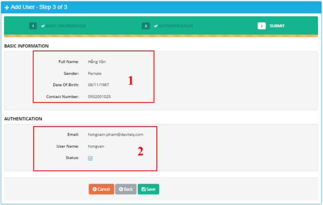
(1) Display basic information of user in step 1.
(2) Display information for sign in in step 2.
3.5.3. Group management
Group is used to assign authorities to users.
- In Home screen, select menu Administrators → select sub-menu Group Management
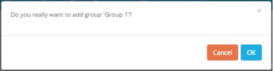
- In screen of group list, click button “Add Group” to create new group of account.
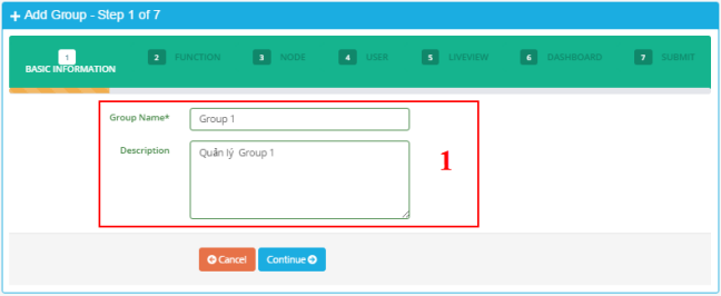

- Enter basic information of group into panel (1).
Group Name: Enter group name. Group name is unique.
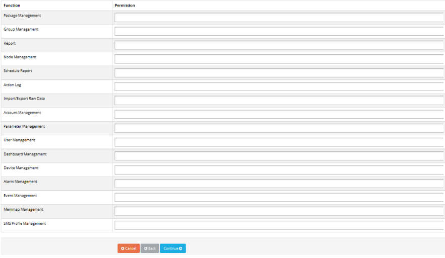
- Select assigned functions for group in area
Only display assigned functions of account. - Click button “Continue” to go to step 3.Screen of step 3 should appear:
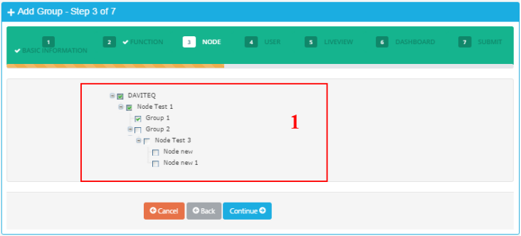
(1) Display available nodes of account. Tick nodes to assign to group.
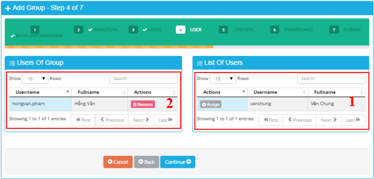
- Display list of users. The users have not been assigned to the group.
- Display list of users which has already been assigned to the group.
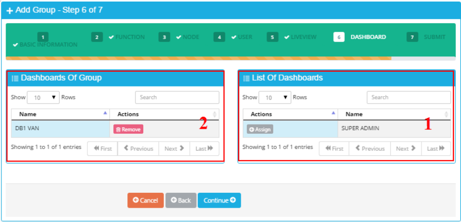
(1) Display list of Dashboard of signing in group. The Dashboard has not been assigned to group.
(2) Display list of Dashboard of signing in group. The Dashboard has already been assigned to group.
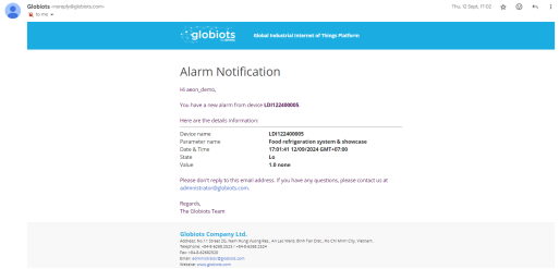
3.5.3. Send notification emails to the account set up prior to receiving alarm signals
4. Troubleshooting
|
No. |
Common Errors |
Solution |
|
1 |
There is an alarm signal at the field device, but it is not reporting to the software |
Step 1. Check the output signal contacts on the field device. Step 2. Check the connection between the alarm device and the LRW-DI sensor. Step 3. Contact Daviteq Technical Support (via Zalo or hotline).
|
|
2 |
Disconnection at a single point |
Step 1. Check for abnormalities at the sensor of the disconnected point (e.g. physical impact, obstruction, etc.) Step 2. Check the power LED of all gateways at the site Step 3. Contact Daviteq Technical Support (via Zalo or hotline) |
|
3 |
Disconnection at a site
|
Step 1. Check the power LED of all gateways at the site Step 2. Contact Daviteq Technical Support (via Zalo or hotline) |
|
4 |
Disconnection at multiple sites | Step 1. Contact Daviteq Technical Support (via Zalo or hotline) |
5. Hardware Connect
5.1. Instructions for replacing the DI node
5.2. Instructions for replacing the battery