Manual for Modbus Sensor
USER GUIDE FOR TRIAXIAL VIBRATION SENSOR - MBRTU-V3A
| MBRTU-V3A-MN-EN-01 |
JUN-2026 |
This document is applied for the following products
|
SKU |
MBRTU-V3A |
HW Ver. |
1 |
FW Ver. |
1 |
|
Item Code
|
V3A-06-485-01 |
Triaxial vibration sensor, RS485 Modbus RTU Output, 6KHz Ultra-low Noise MEMS sensor with Temperature, M6 screw, M12-male 4pin connector, IP67 |
|||
|
V3A-06-485-02 |
Triaxial vibration sensor, RS485 Modbus RTU Output, 6KHz Ultra-low Noise MEMS sensor with Temperature, M6 screw, M12-female 4pin connector, IP67 |
||||
1. Functions Change Log
| HW Ver.
|
FW Ver. |
Release Date |
Function Change |
|
1 |
1 |
13 Jun 26 |
Initial firmware
|
2. Introduction
MBRTU-V3A vibration sensor is 6KHz Ultra-low Noise MEMS sensor with temperature. This sensor utilizes digital temperature sensor delivers high accuracy measurement. Output is RS485 Modbus RTU for easily integrating with any PLC, controller, SCADA, BMS or IoT gateway.
- Digital sensor technology;
- High accuracy;
- Standard RS485 Modbus RTU output;
- Plug & Play.
3. Specification
| Specification | Values |
| Sensor Type | Ultra-low noise 3-axis digital MEMS vibration sensor |
| Measurement axes | X, Y, Z |
| Frequency Bandwidth | 6KHz, +/- 3dB |
| Acceleration range | +/- 16G |
| Sampling rate | 26.667 kHz |
| Resolution | 16 bit |
| Sensitivity | 0.488 mg/LSB |
| Sensitivity tolerance | ±2% typ. at 25°C |
| Sensitivity drift | ±1% typ. over temperature |
| Integrated noise, 0–6.3 kHz | X/Y 6 mg RMS, Z 8.7 mg RMS |
| Integrated noise, 0–1 kHz | X/Y 2.4 mg RMS, Z 3.5 mg RMS |
| Surface temperature measurement | -40 .. + 85 oC with +/- 0.5 oC accuracy typ. after calibration |
| Measurement Output | 8 vibration values for each axis + surface temperature |
| Communication Interface | RS485, ModbusRTU, baud rate of 11520 bps, none parity |
| Power Supply | 7..36VDC max 200mA, Surge Protection for Power supply and RS485 lines |
| Housing | Inodized Aluminium, IP67 |
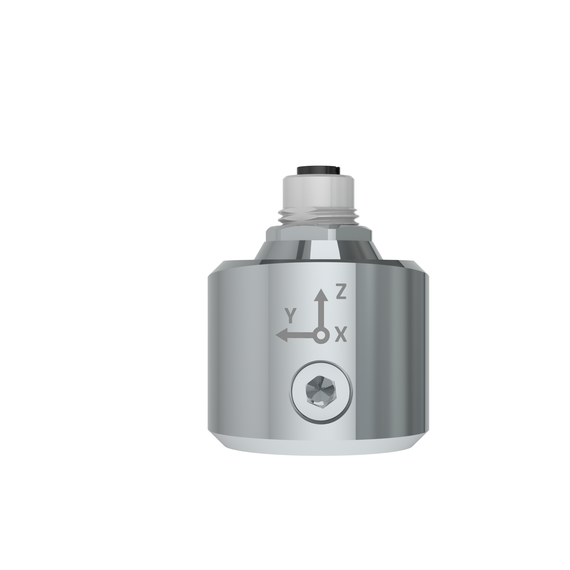
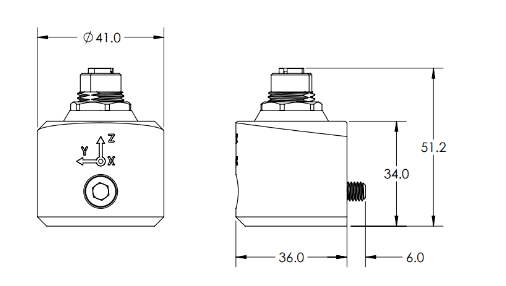
| Mounting | M6x35 through-bolt, optional M5/M4 sleeve, optional magnetic adapter |
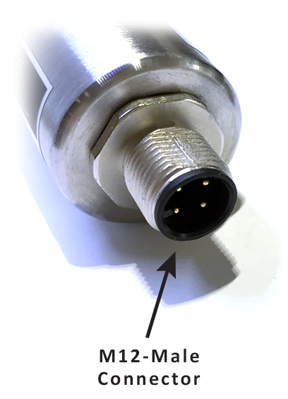
| Connector | M12 male 4-pin, A-coded for V3A-06-485-01 and M12 female 4-pin, A-coded for V3A-06-485-02 |
| Working temperature | -40 .. + 85 oC |
| Dimension | 46 x 42mm (without M12 connector) |
| Weight | < 250 grams |
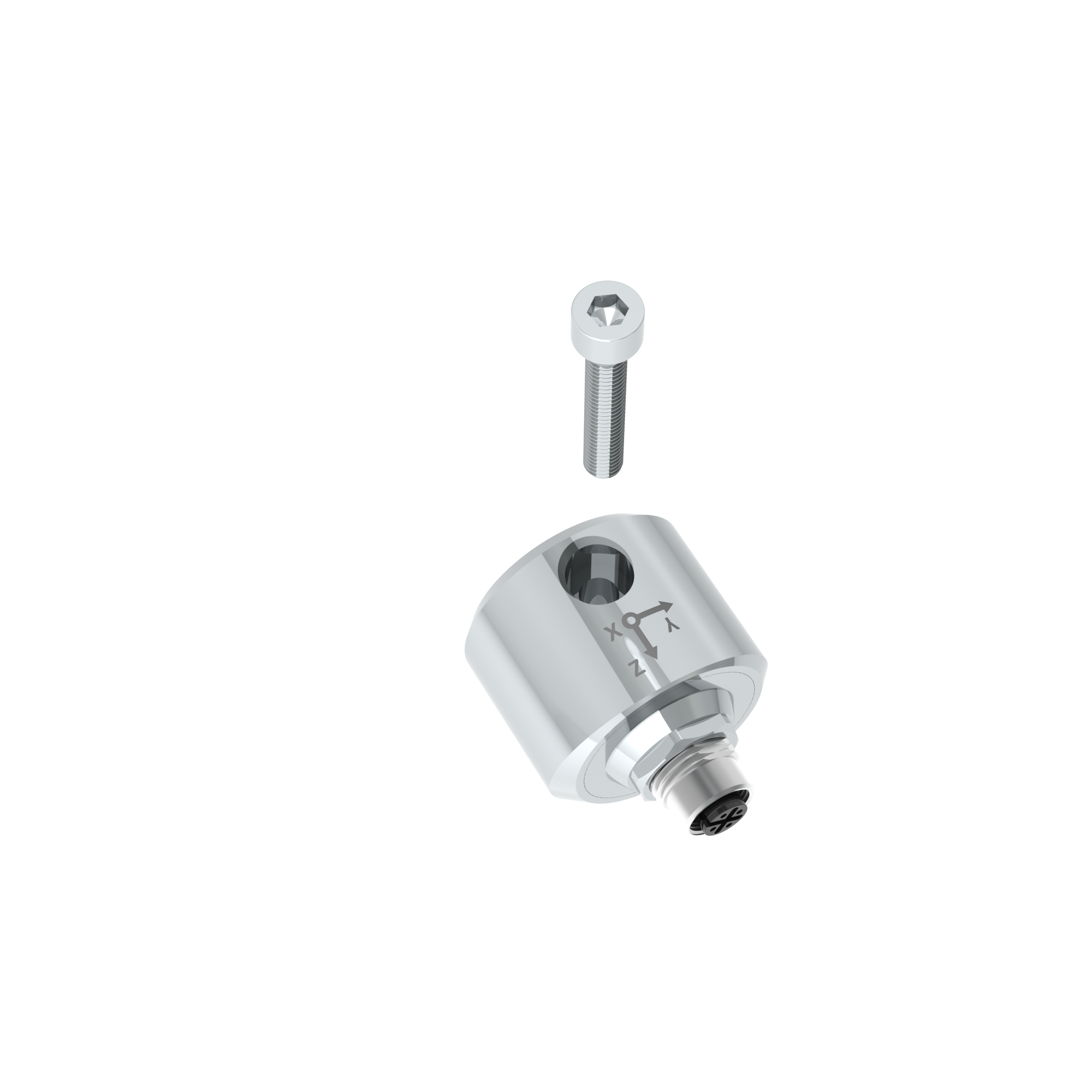
3. Product components
4. Dimensions
5. Wiring
5.1 Electrical connector
5.2 Pinout
Because the sensor uses an M12 electrical connector, please look closely at the pinouts of the M12 electrical connector as shown below.

A - B: RS485/ModbusRTU Output
PWR+: Power supply 7..48VDC
PWR-: Ground, 0VDC
6. Configuration
6.1 Configuration steps
- Connect A pin of sensor M12 connector to RS485+ of Modbus master device (PC, PLC...) and connect B pin of M12 connector to RS485- of Modbus master device (PC, PLC...)
- Connect PWR+ and PWR- to 7-48 VDC power supply
- Use Modbus software to read the sensor with Modbus function of 3 and to write with Modbus function of 16. Details are in memory map registers section
6.2 Memory map registers
| Modbus Register (Dec) | Modbus Register (Hex) | Func Code (Read) | Func Code (Write) | # Reg | Description | End-user Default | Format | Comment |
| 0 | 0 | 3 | None | 2 | FW_CODE | V3A | string | Firmware code |
| 2 | 2 | 3 | None | 4 | FW_VERSION | 1Fmmdd | string | Firmware version mmdd = month / day |
| 6 | 6 | 3 | None | 2 | HW_VERSION | 1H | string | Hardware version v1 |
| 8 | 8 | 3 | None | 2 | X_VELOCITY_RMS_A | float | RMS Velocity of band A, unit of mm/s, for X-axis | |
| 10 | A | 3 | None | 2 | X_ACCELERATION_RMS_B | float | RMS Acceleration of band B, unit of m/s^2, for X-axis | |
| 12 | C | 3 | None | 2 | X_CREST_FACTOR_B | float | Crest factor of band B, for X-axis | |
| 14 | E | 3 | None | 2 | X_KURTOSIS_B | float | Kurtosis factor of band B, for X-axis | |
| 16 | 10 | 3 | None | 2 | X_ACCELERATION_PEAK_C | float | Peak Acceleration of band B, unit of m/s^2, for X-axis | |
| 18 | 12 | 3 | None | 2 | X_CREST_FACTOR_C | float | Crest factor of band C, for X-axis | |
| 20 | 14 | 3 | None | 2 | X_KURTOSIS_C | float | Kurtosis factor of band C, for X-axis | |
| 22 | 16 | 3 | None | 1 | X_SHOCK_COUNT | uint16 | Counter for shock events captured, a shock event is determined by exceeding shock threshold (could be config by SHOCK_THRESHOLD registers), for X-axis | |
| 23 | 17 | 3 | None | 1 | X_TEMPERATURE_X10 | int16 | Temperature = TEMPERATURE_X10 divide by 10, for X-axis | |
| 24 | 18 | 3 | None | 2 | X_SCALE_FACTOR_A | float | Scale factor A for velocity and acceleration values, for X-axis | |
| 26 | 1A | 3 | None | 2 | X_SENSOR_SENSITIVITY | float | Sensor sensitivity, unit of mV/g, for X-axis | |
| 28 | 1C | 3 | None | 2 | X_SHOCK_THRESHOLD | float | Shock threshold to detect/count shock event, unit of G, for X-axis | |
| 30 | 1E | 3 | None | 2 | Y_VELOCITY_RMS_A | float | RMS Velocity of band A, unit of mm/s, for Y-axis | |
| 32 | 20 | 3 | None | 2 | Y_ACCELERATION_RMS_B | float | RMS Acceleration of band B, unit of m/s^2, for Y-axis | |
| 34 | 22 | 3 | None | 2 | Y_CREST_FACTOR_B | float | Crest factor of band B, for Y-axis | |
| 36 | 24 | 3 | None | 2 | Y_KURTOSIS_B | float | Kurtosis factor of band B, for Y-axis | |
| 38 | 26 | 3 | None | 2 | Y_ACCELERATION_PEAK_C | float | Peak Acceleration of band B, unit of m/s^2, for Y-axis | |
| 40 | 28 | 3 | None | 2 | Y_CREST_FACTOR_C | float | Crest factor of band C, for Y-axis | |
| 42 | 2A | 3 | None | 2 | Y_KURTOSIS_C | float | Kurtosis factor of band C, for Y-axis | |
| 44 | 2C | 3 | None | 1 | Y_SHOCK_COUNT | uint16 | Counter for shock events captured, a shock event is determined by exceeding shock threshold (could be config by SHOCK_THRESHOLD registers), for Y-axis | |
| 45 | 2D | 3 | None | 1 | Y_TEMPERATURE_X10 | int16 | Temperature = TEMPERATURE_X10 divide by 10, for Y-axis | |
| 46 | 2E | 3 | None | 2 | Y_SCALE_FACTOR_A | float | Scale factor A for velocity and acceleration values, for Y-axis | |
| 48 | 30 | 3 | None | 2 | Y_SENSOR_SENSITIVITY | float | Sensor sensitivity, unit of mV/g, for Y-axis | |
| 50 | 32 | 3 | None | 2 | Y_SHOCK_THRESHOLD | float | Shock threshold to detect/count shock event, unit of G, for Y-axis | |
| 52 | 34 | 3 | None | 2 | Z_VELOCITY_RMS_A | float | RMS Velocity of band A, unit of mm/s, for Z-axis | |
| 54 | 36 | 3 | None | 2 | Z_ACCELERATION_RMS_B | float | RMS Acceleration of band B, unit of m/s^2, for Z-axis | |
| 56 | 38 | 3 | None | 2 | Z_CREST_FACTOR_B | float | Crest factor of band B, for Z-axis | |
| 58 | 3A | 3 | None | 2 | Z_KURTOSIS_B | float | Kurtosis factor of band B, for Z-axis | |
| 60 | 3C | 3 | None | 2 | Z_ACCELERATION_PEAK_C | float | Peak Acceleration of band B, unit of m/s^2, for Z-axis | |
| 62 | 3E | 3 | None | 2 | Z_CREST_FACTOR_C | float | Crest factor of band C, for Z-axis | |
| 64 | 40 | 3 | None | 2 | Z_KURTOSIS_C | float | Kurtosis factor of band C, for Z-axis | |
| 66 | 42 | 3 | None | 1 | Z_SHOCK_COUNT | uint16 | Counter for shock events captured, a shock event is determined by exceeding shock threshold (could be config by SHOCK_THRESHOLD registers), for Z-axis | |
| 67 | 43 | 3 | None | 1 | Z_TEMPERATURE_X10 | int16 | Temperature = TEMPERATURE_X10 divide by 10, for Z-axis | |
| 68 | 44 | 3 | None | 2 | Z_SCALE_FACTOR_A | float | Scale factor A for velocity and acceleration values, for Z-axis | |
| 70 | 46 | 3 | None | 2 | Z_SENSOR_SENSITIVITY | float | Sensor sensitivity, unit of mV/g, for Z-axis | |
| 72 | 48 | 3 | None | 2 | Z_SHOCK_THRESHOLD | float | Shock threshold to detect/count shock event, unit of G, for Z-axis | |
| 74 | 4A | 3 | None | 1 | DEBUG_I2C_ERROR | hex | I2C read error code. 0: No error. 1: Error. |
|
| 75 | 4B | 3 | None | 196 | spare | hex | spare | |
| 271 | 10F | 3 | 16 | 2 | X_CONFIG_SCALE_FACTOR_A | float | Configuration of SCALE_FACTOR_A, for X-axis | |
| 273 | 111 | 3 | 16 | 2 | X_CONFIG_SENSOR_SENSITIVITY | float | Configuration of sensor sensitivity, unit of mV/g, for X-axis | |
| 275 | 113 | 3 | 16 | 2 | X_CONFIG_SHOCK_THRESHOLD | float | Configuration of shock threshold to detect/count shock event, unit of G, for X-axis | |
| 277 | 115 | 3 | 16 | 2 | Y_CONFIG_SCALE_FACTOR_A | float | Configuration of SCALE_FACTOR_A, for Y-axis | |
| 279 | 117 | 3 | 16 | 2 | Y_CONFIG_SENSOR_SENSITIVITY | float | Configuration of sensor sensitivity, unit of mV/g, for Y-axis | |
| 281 | 119 | 3 | 16 | 2 | Y_CONFIG_SHOCK_THRESHOLD | float | Configuration of shock threshold to detect/count shock event, unit of G, for Y-axis | |
| 283 | 11B | 3 | 16 | 2 | Z_CONFIG_SCALE_FACTOR_A | float | Configuration of SCALE_FACTOR_A, for Z-axis | |
| 285 | 11D | 3 | 16 | 2 | Z_CONFIG_SENSOR_SENSITIVITY | float | Configuration of sensor sensitivity, unit of mV/g, for Z-axis | |
| 287 | 11F | 3 | 16 | 2 | Z_CONFIG_SHOCK_THRESHOLD | float | Configuration of shock threshold to detect/count shock event, unit of G, for Z-axis |
7. Installation
- Create a hole on the installation surface with depth >= 6mm and thread M6x1.0
- Install the sensor to the hole using provided bolt

8. Calibration
The delivered sensor should be factory-calibrated. If customer would like to re-calibrate, please follow below process
8.1 Calibration preparation
- V3A sensor
- Axis Y/ Z calibration support fixture.
- A vibration calibrator with an M6 threaded mounting slot, capable of delivering standard 10 mm/s velocity RMS at 80Hz under a minimum 500g load.
- Modbus/RS485 to USB cable
- 7-48 VDC power supply
- Modbus Master Log software/application
- PC
8.2 Calibration setup
- Connect sensor's RS485 port to the PC
- Connect PWR+, PWR- to 7-48VDC power supply
- Open Modbus Master Log software/application on PC
- Configure the baud rate of 115200 bps, parity of none for the software/application for Modbus communication
- Configure parameters to read are X_SENSOR_SENSITIVITY, X_VELOCITY_RMS_A, Y_SENSOR_SENSITIVITY, Y_VELOCITY_RMS_A, Z_SENSOR_SENSITIVITY, Z_VELOCITY_RMS_A with Modbus function of 3
8.3 X/Y/Z axis calibration
8.3.1 X axis calibration
- Install the sensor to the vibration calibrator with provided bolt
- Set the vibration calibrator to output a steady reference signal of 80Hz at standard 10 mm/s velocity RMS.
- Log about 30 values of X_VELOCITY_RMS_A parameters
- Calculate the average value of X_VELOCITY_RMS_A
- Calculate X_CONFIG_SENSOR_SENSITIVITY = X_SENSOR_SENSITIVITY * standard RMS velocity (10 mm/s) / (average value of X_VELOCITY_RMS_A in step 4).
- Write calculated X_CONFIG_SENSOR_SENSITIVITY to the sensor with Modbus function of 16
- Re-read the X_VELOCITY_RMS_A parameters. The value should be standard RMS velocity (10 mm/s)
- Power off the vibration calibrator and unmount the sensor from the calibrator.
8.3.2 Y axis calibration
- Secure the sensor onto the Axis Y/Z calibration support fixture then bolt the entire assembly back onto the calibrator on the target Y axis
- Set the vibration calibrator to output a steady reference signal of 80Hz at standard 10 mm/s velocity RMS.
- Log about 30 values of Y_VELOCITY_RMS_A parameters
- Calculate the average value of Y_VELOCITY_RMS_A
- Calculate Y_CONFIG_SENSOR_SENSITIVITY = Y_SENSOR_SENSITIVITY * standard RMS velocity (10 mm/s) / (average value of Y_VELOCITY_RMS_A in step 4).
- Write calculated Y_CONFIG_SENSOR_SENSITIVITY to the sensor with Modbus function of 16
- Re-read the Y_VELOCITY_RMS_A parameters. The value should be standard RMS velocity (10 mm/s)
- Power off the vibration calibrator and unmount the sensor from the calibrator.
8.3.3 Z axis calibration
- Secure the sensor onto the Axis Y/Z calibration support fixture then bolt the entire assembly back onto the calibrator on the target Z axis
- Set the vibration calibrator to output a steady reference signal of 80Hz at standard 10 mm/s velocity RMS.
- Log about 30 values of Z_VELOCITY_RMS_A parameters
- Calculate the average value of Z_VELOCITY_RMS_A
- Calculate Z_CONFIG_SENSOR_SENSITIVITY = Z_SENSOR_SENSITIVITY * standard RMS velocity (10 mm/s) / (average value of Z_VELOCITY_RMS_A in step 4).
- Write calculated Z_CONFIG_SENSOR_SENSITIVITY to the sensor with Modbus function of 16
- Re-read the Z_VELOCITY_RMS_A parameters. The value should be standard RMS velocity (10 mm/s)
- Power off the vibration calibrator and unmount the sensor from the calibrator.
9. Support contacts
|
Manufacturer Daviteq Technologies Inc
No.11 Street 2G, Nam Hung Vuong Res., An Lac Ward, Binh Tan Dist., Ho Chi Minh City, Vietnam. Email: support@daviteq.com | https://www.iot.daviteq.com/ |