Manual for NBIoT/CATM1 device
- Manual for WSNBM-AQUA | FW 1
- 1. Quick installation guide for WSNBM-AQUA
- 2. Maintenance for WSNBM-AQUA
- 3. Advanced guide for WSNBM-AQUA
- 4. Product Specifications for WSNBM-AQUA
- 5. Warranty for WSNBM-AQUA
- Manual for WSNBM-AG | FW1
Manual for WSNBM-AQUA | FW 1
1. Quick installation guide for WSNBM-AQUA
This manual is applied to the following products:
| Item code | Hardware version | Firmware Version | Firmware released date | Change information |
|
WSNBM-AQUA-1G10-IA
WSNBM-AQUA-2G10-IA
|
1 | 1 | 10 June 2025 | Initial firmware |
1.1 Introduction
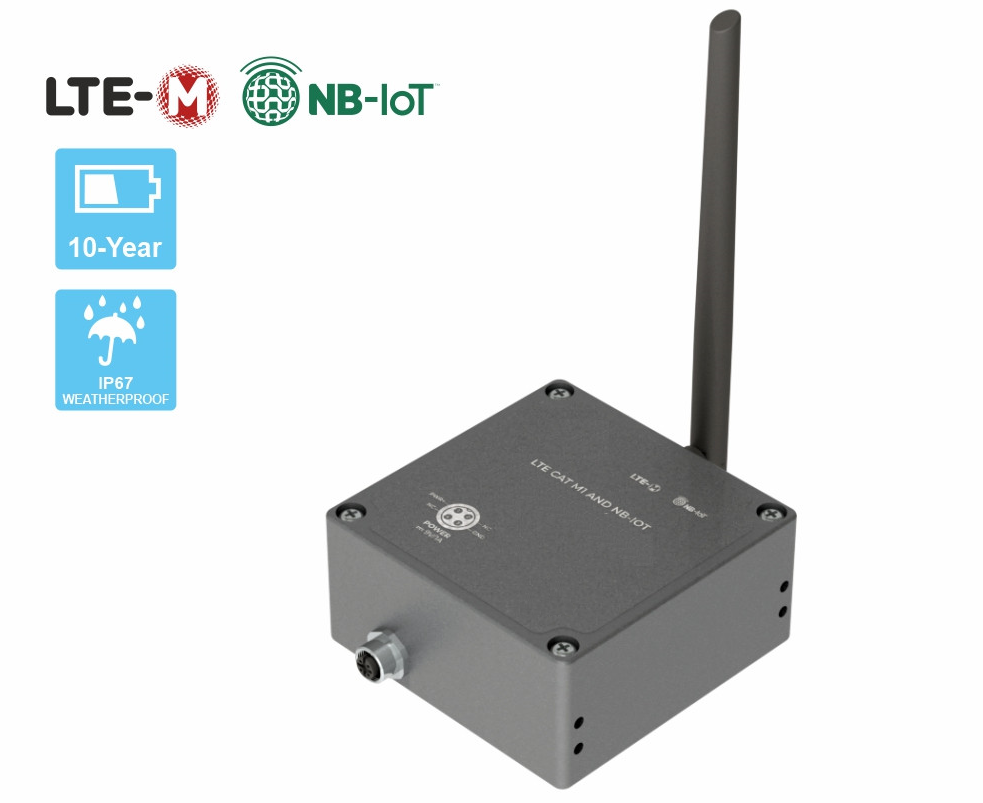
The WSNBM-AQUA is a cutting-edge NB-IoT and LTE Cat M1 data logger tailored for comprehensive water pipeline network monitoring. It includes pulse inputs, an RS485 Modbus RTU Master Node, and built-in pressure sensors. Designed for long-term performance, the device operates efficiently on one or two batteries, offering a lifespan of 5 to 10 years. With support for global frequency bands, it is an ideal solution for city water networks, industrial parks, smart utility systems, and various other applications.

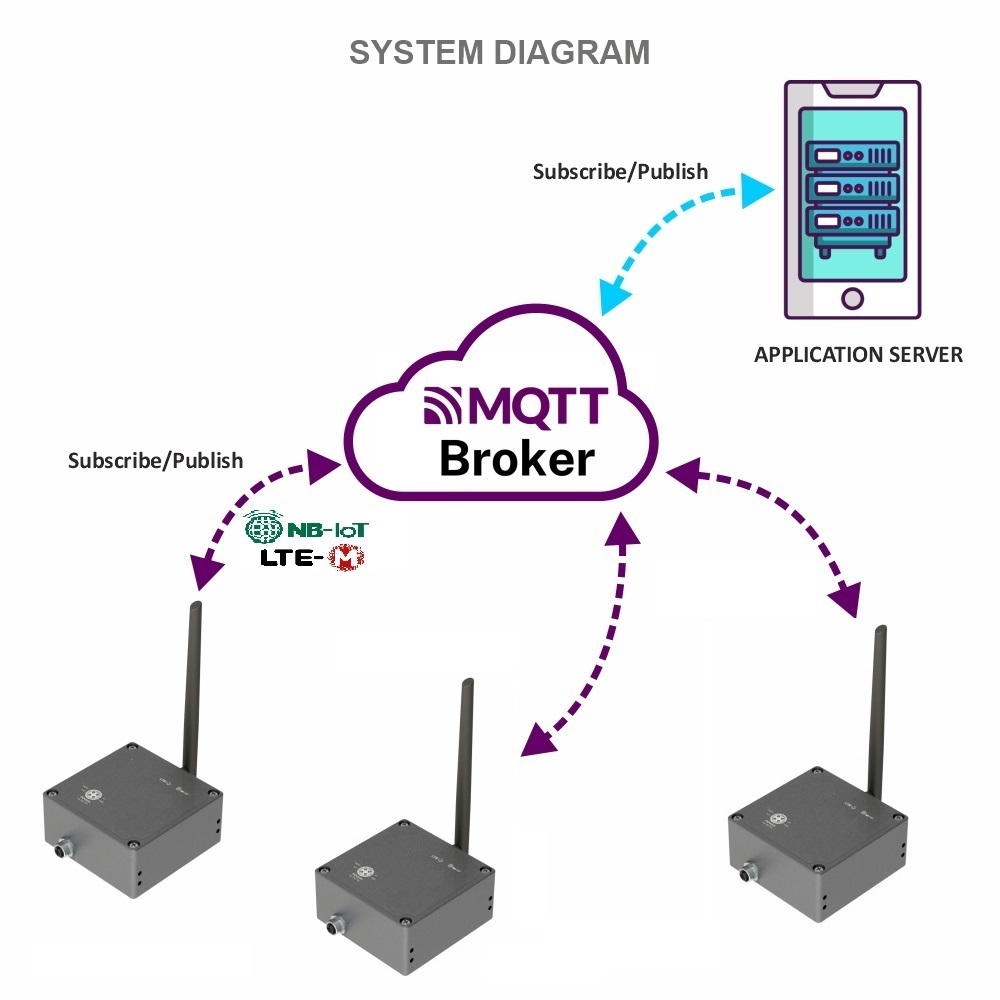
1.1.1. The MQTT data logger system architecture
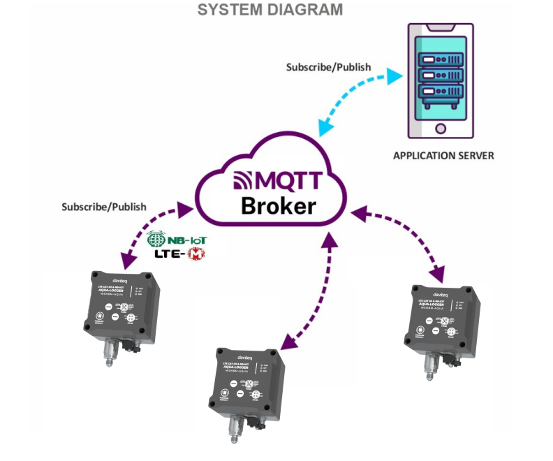
System components:
- Aqua logger: publish the the data messages to the broker and subscribe request of configuration change messages from the application
- MQTT broker: is the server that receives the data messages from the loggers then route them to the application. In addition, the broker also receives request of configuration change messages from the application and then route them to the logger
- MQTT application: subscribe the data messages from loggers and publish request of configuration change messages to the logger
1.1.2. How to set up the MQTT system?
Please follow these steps:
- Configure on MQTT broker: the user, password, QoS, CA file, SSL
- Configure on the logger: MQTT configurations (host, port, user, password, CA file, SSL on/off, QoS, message retain), CAT M1/NB-IoT configurations (network category, frequency bands, RAT search sequence)
- Configure on the application: host, port, user, password, QoS, CA file
- Insert the CAT M1/NB-IoT SIM to the logger, then insert the batteries/power supply. The logger will publish the messages to the MQTT broker and then the broker will route the messages to the application
1.2 When does device publish the topic?
The device will publish the topic following cases to MQTT brokers:
Case 1: When device is power-up, the device will publish the first topic called START_UP. The payload will tell the user the full device configurations and device health statuses.
Case 2: In every interval time (pre-configured), for example, 24 hours, it will publish the topic called HEARTBEAT. The payload will tell the user the full device configurations and device health statuses.
Case 3: If users want to get the value of device configurations and device health immediately, user could force the device to publish the CONFIG-HEALTH-CHECK topic. The device could be forced by applying the magnet key in more than 5s.
Case 4: During the commissioning, testing, or calibration logger, the user can force the device to publish the topic to get the data immediately. This topic is called FORCE. The payload will provide data like raw measured value, scaled measured values, and device health. It can be forced by applying the magnet key on the reed switch in 1s;
Case 5: Then, in every interval time (pre-configured), for example, 10 minutes, it will publish the topic called CYCLE. The payload will tell the user the following data like measured values and device health. To change the cycle of data sending, you can change the value of the CYCLE_PERIOD parameter.
Case 6 : If the application requests to change device configurations, the application will publish the CONFIG-REQUEST topic to the MQTT broker and the device subscribe the CONFIG-REQUEST topic. After that, the device will change the configuration as request in the CONFIG-REQUEST topic and publish CONFIG-RECEIPT topic. The payload of CONFIG-RECEIPT topic contains the result of the configuration changes.
1.3 Default Configuration
Please refer to the END USER DEFAULT column in the memory map file at the section 1.9 Payload Document and Configuration Tables
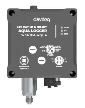
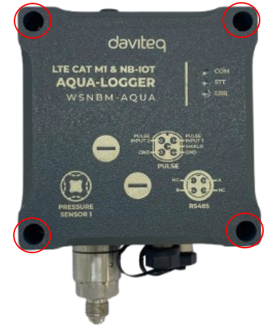
1.4 Hardware overview
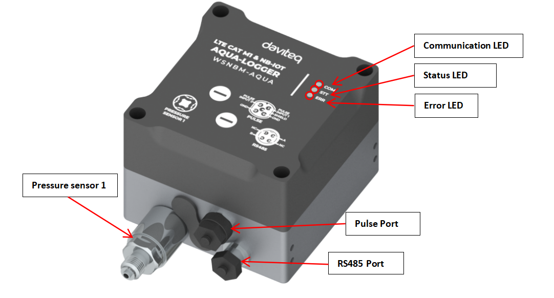
LED PRINCIPLE
| OFF | FLASHING | |
| COM LED (Red) | Power-off OR sleep status | Operation status (measurement/data sending) |
| STT LED (Red) | Configuration port-off | Configuration port -on |
| ERR LED (Red) | Power Off or No Error | Hardware Error |
1.5 Power supply
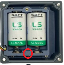
- Rechargeable battery:
-
Use 2 x D-size battery 3.6V LiSOCl2 with 17Ah;
Recommend to use SAFT LS33600 or equivalent from Tadiran.

Procedures to insert batteries
- Open the device upper housing by removing 4 screws
- Open the battery cover by removing a screw, then slide the cover upward slightly to move the cover out of the latch, then take out the cover
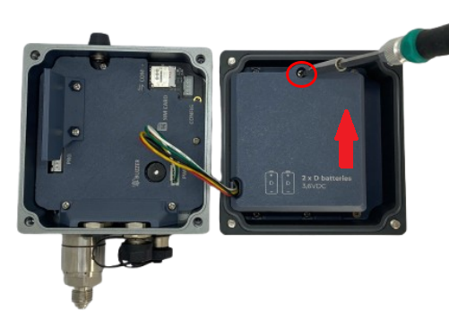
Note:
Hard slide the battery cover might result in broken the latch of the battery cover
- Unplug power connector from the mainboard, and wait 5 minutes

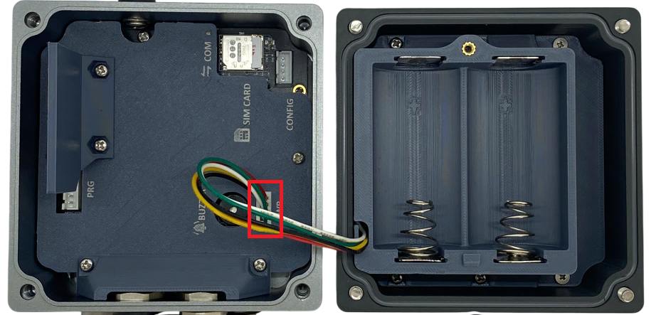
- Insert batteries to the battery holder with right polarity
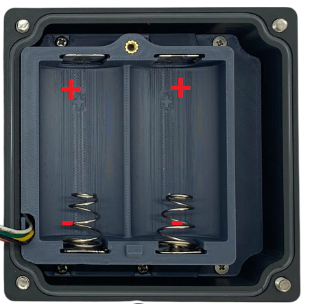
Note:
Wrong polarity might cause the device faulty
- Plug the power connector back
- Close the battery cover and device upper housing
1.6 What's in the Package?

1.7 Guide for Quick Test
- MQTT broker's settings: host, post, user, password CAT file (if applicable), QoS
- Cellular settings: CAT M1/NB IoT, frequency bands
Step 2: Configure on the logger the MQTT configurations (host, port, user, password, CA file, SSL on/off, QoS, message retain), CAT M1/NB-IoT configurations (network category, frequency bands, RAT search sequence) with offline tool and the template.
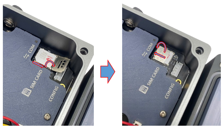
- Open the device upper housing by removing 4 screws
- Insert the SIM to the device: Push the SIM holder cover slightly, open the SIM holder cover, insert the SIM to the holder, then close the SIM holder cover and then push the SIM holder cover back to origin position.
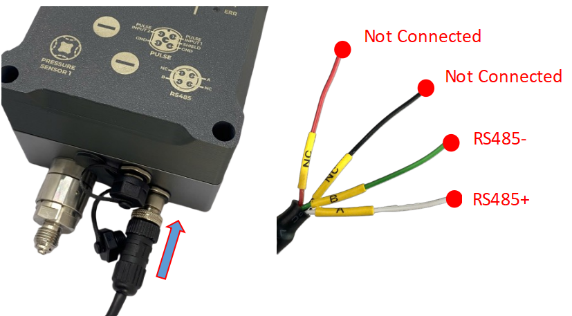
Step 4: Connect RS485 Modbus RTU device to the logger
RS485 + wire (A label) of the cable to RS485 + of Slave device/meter
RS485 - wire(B label) of the cable to RS485 - of Slave device/meter
Plug M12 male connector of the cable to M12 female connector of the logger
Step 5: Connect pipes from the pressurized point on the pipeline to the pressure sensors on the logger
Step 6: Insert the batteries into the device. Please refer section 1.3 Battery for details
Step 7: After supplying the power, the device will publish topics to the MQTT broker. The application subscribes the topics and decode the payload to get measured values. Details of topic name and payload is at Section Section Payload Document and Configuration Tables.
1.8 Installation and Wiring
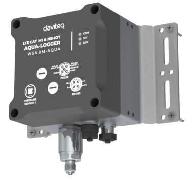
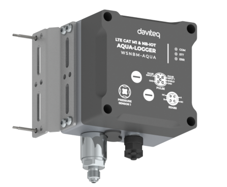
1.8.1 Installation drawings
Dimension drawings for installation as below

1.8.2 Check list for installation
Please follow the checklist below for a successful installation:
1. Have you studied the dimensions of the device as above drawings?
2. Have you tested and make sure the device have been connected successfully as Section "1.4 Guide for Quick Test" above?
3. Have the device been configured properly?
4. Have the device been calibrated or validated?
5. Then you can start to install the device at site. Please check the following Installation Notes for Sensor Part (if available) before installation.
1.8.3 Selection for installation location
- Make sure the site is good enough for CAT-M1/NB IoT signals.
- Choose a location far from light, heat, and vibration.
- DO NOT install the logger or its antenna inside a completed metallic box or housing because the cellular signal can not pass through the metallic wall. The housing is made from Non-metallic materials like plastic, glass, wood, leather, concrete, and cement…is acceptable.
1.8.4 Sample installation

1.9 Payload Document and Configuration Tables
Pease click below link for:
- Payload decoding of Uplink messages;
- Payload encoding of Downlink messages;
- Configuration Tables of device.
Click Payload document and configuration table to download Payload Document and Configuration Tables
1.10 How to connect device to MQTT Broker
Please find below the examples of adding Daviteq's MQTT device to the following MQTT broker:
- Mosquitto MQTT broker
2. Maintenance for WSNBM-AQUA
2.1 Troubleshooting
- If the device cannot connect to the MQTT broker at the first time, it is the Communication Problem;
- If the device status like battery, RSSI level, data status or other communication is normal, but the measured values are not updated or wrong, it would be the problems of Sensor part;
- If the data coming to MQTT broker is not frequently as expected, the problem would be Communication.
Please refer below the troubleshooting guide for Communication and Sensor Part.
2.1.1. Troubleshooting for Communication
2.1.2. Troubleshooting for Sensor Part
| Symptom | Cause | Solution |
|---|---|---|
|
Modbus value remains unchanged on Aqua Logger and/or Modbus Exception = 0x000F is returned from modbusHexValue data, indicating an error in the Modbus RTU communication process |
The slave device is not powered or has failed, resulting in no data response. |
Check visually, verify power supply and ensure the Slave Device is operational. |
|
The RS485 communication port on the slave device is damaged/malfunction or not transmitting. |
Test the slave device with another Modbus master/PC or use RS485 diagnostic tools to confirm signal output. | |
|
The RS485 cable between Aqua Logger and the slave device is damaged, disconnected, or loose connection. |
Perform visual inspection, continuity testing, and ensure all M12/terminal connectors are properly tightened. | |
|
The RS485 port on Aqua Logger is defective or hardware failure. |
Verify using the configuration software or RS485 test tools, or contact Daviteq support. | |
|
Modbus communication configurations such as Slave ID, Baud rate, Parity, Stop Bit have been modified accidentally. |
Check and restore correct settings to match the Aqua Logger’s communication configuration. | |
| Aqua Logger’s RS485 Modbus settings have been modified accidentally. | Use the Daviteq configuration Modbus tool with customer template to read, verify, and restore the correct settings. |
2.2 Maintenance
3. Advanced guide for WSNBM-AQUA
3.1 Principle of Operation
Daviteq WSNBM-AQUA comprises 04 parts linked internally:
• Pressure Sensor
• RS485 ModbusRTU Master
• Device controller
• CAT-M1/NB IoT modem
3.1.2. The parameters in published topic name
- SKU: Device SKU, read from DEVICE_SKU parameter in the device memory, max 20 characters, data type of string.
- DEVICE NAME: Device name, read from DEVICE_NAME parameter in device memory, max 20 characters, data type of string.
- DEVICE SN: Device serial number, read from DEVICE_SN parameter in device memory, 20 characters, data type of string.
- DEVICE ALIAS: Device alias, read from DEVICE_ALIAS parameter in device memory, max 20 characters, data type of string.
- TOPIC TYPE: Fixed type of the topic. One of below topic type:
-STARTUP
-HEARBEAT
-CONFIG-HEALTH-CHECK
-FORCE
-CYCLE
-CONFIG-RECEIPT
-CONFIG-REQUEST
3.1.3. Primary output values in the payload of published topics
3.1.4. Secondary output values in the payload of published topics
3.1.5. The parameters in subscribed topic name
- SKU: Device SKU, read from DEVICE_SKU parameter in the device memory, max 20 characters, data type of string.
- DEVICE NAME: Device name, read from DEVICE_NAME parameter in device memory, max 20 characters, data type of string.
- DEVICE SN: Device serial number, read from DEVICE_SN parameter in device memory, 20 characters, data type of string.
- DEVICE ALIAS: Device alias, read from DEVICE_ALIAS parameter in device memory, max 20 characters, data type of string.
- TOPIC TYPE: Fixed type of the topic. The topic type is CONFIG-REQUEST, a request to change the parameter.
3.1.6. Parameters in the payload of subscribed topic name
Subscibed Topic Type: Fixed type of the topic is CONFIG-REQUEST. This parameter is topicType in the published topic's payload.
Epoch Time: Topic's Epoch Time format, unit of millisecond. This parameter is epochTime in the published topic's payload.
Device Serial Number: Device serial number. This parameter is deviceSerialNumber in the published topic's payload.
Start Address: Start address of the changed configuration, in decimal. This parameter is startAddress in the published topic's payload.
Register Length: Register number of changed configuration, in decimal, max length = 400 hexadecimal value. This parameter is registerLength in the published topic's payload.
Requested Value: Requested value for the configuration change, in hexadecimal. This parameter is requestedValue in the published topic's payload.
3.1.7. Device operation flow chart
3.1.8. Device operation principle description
When a device subscribes to the CONFIG-REQUEST topic successfully, device implements the configuration change request and publishes CONFIG-RECEIPT topic to acknowledge the receipt of the CONFIG-REQUEST topic.
3.2 Configuration
3.2.1. How to configure the device?
Sensor configuration can be configured in 02 methods:
Method 1: Online configuring via Subscribing CONFIG-REQUEST topic from MQTT Application.
Method 2: Offline configuring via Offline cable.
3.2.2 Which Parameters are configured?
Please check Part E. MEMORY MAP in Section 1.9 Payload Documents above.
3.2.3 Online configuring via subscribing CONFIG-REQUEST topic from MQTT Application.
Please refer Part C. SUBSCRIBE TOPIC in Section 1.9 Payload Documents above.
3.2.4 Offline configuring via Offline cable.
Please download the Configuration Template File of this sensor to be used in Step 4 below.
Click Download CSV file to download the Configuration Template File
Instructions for offline configuration of the Seismic sensors. Please follow the following steps.
Prepare equipment and tools
The following items must be prepared for configuration.
- A PC using the Windows OS (Windows 7 or above versions). The PC installed the COM port driver of the Modbus configuration cable (if needed). The driver is at link: Modbus Configuration Cable COM port driver for PC and the instruction to install the driver at link: How to install the driver.
- A Modbus configuration cable
- A M12-CAB-CONFIG cable
Download and launch Modbus configuration software
-
Click the link below to download Modbus configuration software:
Click Modbus configuration software to download the software
After downloading the software, unzip the file named Modbus Configuration.zip and then copy the extracted folder to the storage drive for long-term use.
-
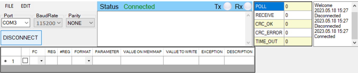
Open the folder, double click on the file Modbus Configuration Tool Version.exe to launch the software and the software interface as below:
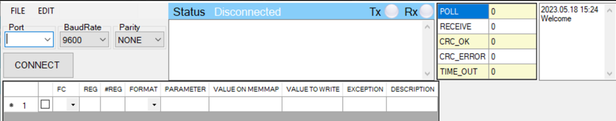
Note: The software only runs on Microsoft Windows OS (Windows 7 and above)
Connect the cable and configure the sensor
Step 1:
Connect the PC to the Battery Pack using the configuration cable and converter cable
- Use the configuration cable (Item code: TTL-LRW-USB-01).
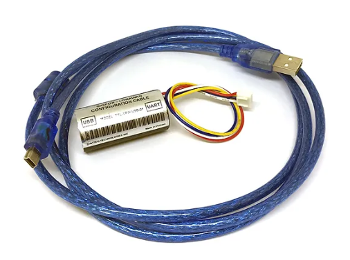
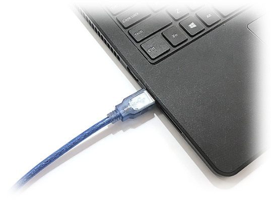
- Connect the USB-A plug into the USB-A socket of the PC.
Step 2:
On the configuration software, choose the relevant Port (the USB port which is the cable plugged in) and set the BaudRate: 115200, Parity: none
Step 3:
Step 4:
Import the configuration template file of the sensor (as above link) to the software: click menu File/ Import New and then browse the relevant sensor template file (csv file) and click Open to import the template file.
Each sensor type has its own template file. Refer to the sensor's manual to download the correct file.
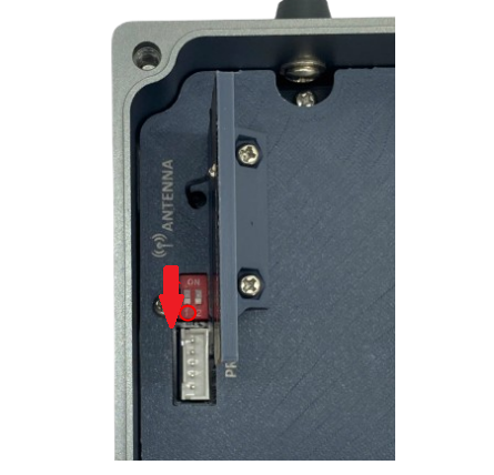
Step 5: Open the housing of the sensor and quickly plug the connector of the configuration cable into sensor's modbus configuration port. After that, turn on the switch 1. After the switch 1 is on, the software will read the parameter values automatically.
|
- Open the housing of the sensor. |
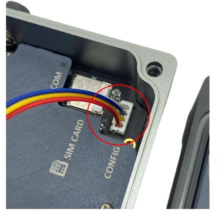 - Plug the cable connector into sensor's Modbus configuration port.Note: this port is located at a different location, depends on the sensor type |
- Turn on the switch 1 |

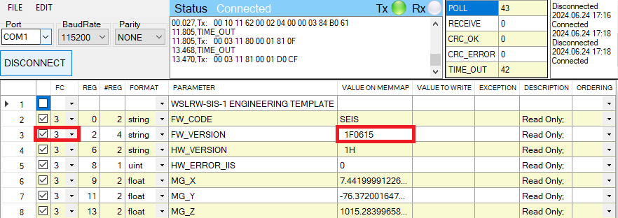
Step 6: Read the current value of the parameter with function 3
- At the relevant row of the parameter, check box 3 on column FC to read the value of the parameter. The read value is shown on VALUE ON MEMMAP column.
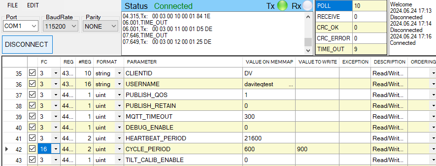
Step 7: Write the new setting to the parameter with function 16
- Double click on the column VALUE TO WRITE of the parameter and input the new setting of the parameter
- Uncheck the tick on the FC column of the parameter, click on the arrow, select 16 and then check on the FC column to write a new setting to the parameter. The WRITE_OK text will show on EXCEPTION column if the software successfully writes the setting.
- Repeat step 6 to read the setting of the parameter for checking.
Step 8: Turn off switch 1 (configuration switch) of aqua logger
For some critical parameters of the sensor, the password in "password for setting" must be written before writing the new settings to these parameters.
Only read/write registers are allowed to write.
After completing configuration, if the switch 1 (configuration switch) is NOT switched off, the battery life will be shorten.
Troubleshooting of offline configuration
| No. | Phenomena | Reason | Solution |
|---|---|---|---|
| 1 | The status on the software always shows Disconnected although the configuration cable is connected to the PC | The selected COM port is incorrect | Select the correct COM port to which the configuration cable connects to PC |
| The configuration cable is defective | Check the configuration cable | ||
| 2 | The software reads no value after importing the right template and connecting the right cable. | The cable is defective or lost connection | Check or replace the new configuration cable |
| The USB port is defective | Check USB port | ||
| There is no power supply to the sensor via configuration cable | Check the power line of the cable | ||
| The sensor or sensor port is defective | Check the sensor and sensor port | ||
| 3 | No COM port appears in the Port list | No configuration cable is plugged into the PC | Plug the cable to the PC |
| The cable driver is not installed on the PC | Install the driver for the PC | ||
| 4 | The parameter table on the software is empty | The template file has not been imported | Click menu File and sub-menu Import New to import the template file |
| 5 | The parameter table on the software does NOT match the memory map table of the sensor. | The wrong template file was imported. | Go to the correct manual page of the product and download the right template file, then import the template file into the software. |
3.3. Update CA file to WSNBM-AQUA
3.3.1. Upload the CA file to a download server
The CA file must be uploaded to a server that supports direct download functionality.
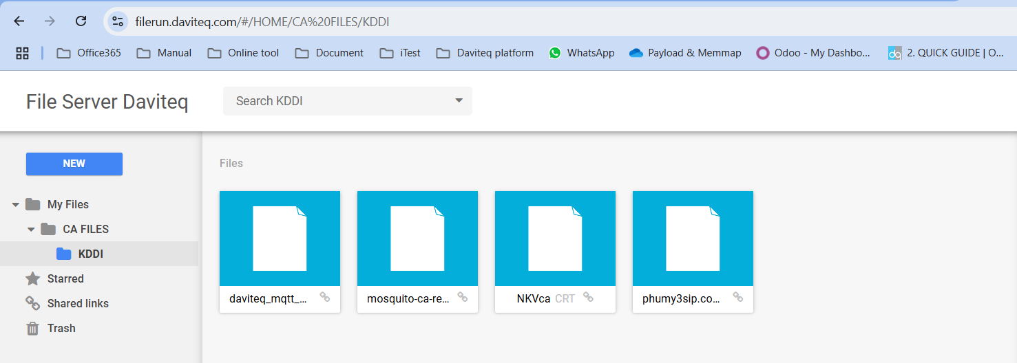
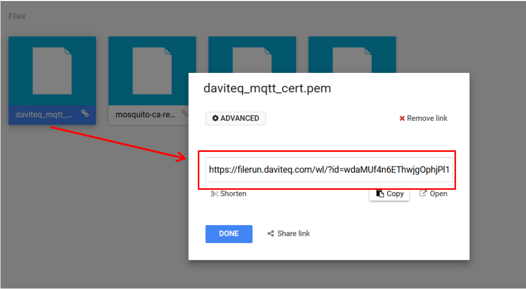
Get the CA file link after uploading successfully
3.3.2. Connect the PC to Aqua logger via configuration cable
Refer to section 3.2.4 Offline configuring via Offline cable for instructions on configuring the Aqua logger
Download the template file for uploading CA file from the link
- After connecting the configuration cable from PC to Aqua logger, open the configuration software and import the template file for uploading the CA file
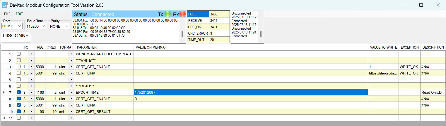
- Wait until the logger is connected to the internet (Indicated by EPOCH_TIME = REAL TIME)
Online tool for converting Epoch time to real time in the link
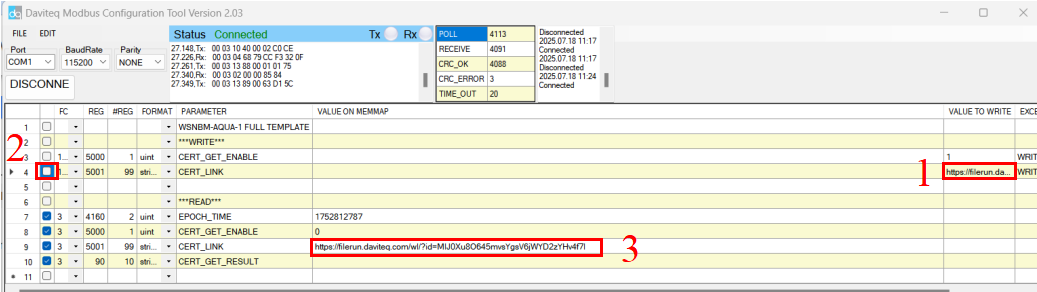
3.3.3. Configure the logger to automatically download the CA file from server
- Input the download link of CA file (in section 3.3.1) into the cell in VALUE TO WRITE column corresponding to CERT_LINK(1)
- Tick the cell corresponding to CERT_LINK as in the picture below (2) to write the link to the logger.
- Wait a few seconds, then check the value in the cell (3). Ensure the cell display the correct download link of the CA file.
3.3.4. Verify that the CA File has been uploaded successfully.
- Tick the cell corresponding to CERT_GET_ENABLE (1) to enable the logger download new CA file
- Wait a few seconds, then check the value in the cell (2), ensure the cell display the value 1
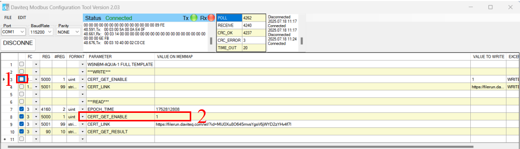
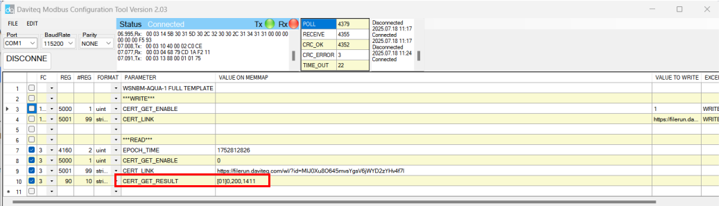
- Continue waiting for a minute, then check the value in the cell corresponding to CERT_GET_RESULT. If the cell displays the value in the same format as shown in the picture below, the CA file was uploaded successful.
In the picture, 1411 is the length of the CA file. Each CA file will have its own value.
4. Product Specifications for WSNBM-AQUA
| MEASUREMENT | |
| Standard Inputs | 02 x Pulses, 1 x RS485 Modbus RTU Master |
| Optional Input | 1 or 2 Pressure Sensors |
| Digital Inputs |
2-Digital channel inputs with dry-contact or voltage input (max 3.3VDC) DI Functions: Logic Detecting or Pulse Counting Logic Detecting: 2 channels, recommended minimum interval time between 02 statuses is 5 seconds. Pulse Counting: 2 channels, max frequency 100Hz, minimum Pulse width (low or high) is 200μS, counter is uint32 type. |
| RS485 Input port |
1 x RS485 master port Protocol: Modbus RTU |
| Pressure Sensor |
Advanced Piezo technology Measurement range: Select 0-10 barg, 0-16 barg, 0-20 barg Over pressure protection: 1.5 x span Accuracy & Stability: 0.25% or 0.5% of span, < 0.2% span/ year Wetted parts: 304SS/316SS Measuring Fluids: Any fluid which is workable with materials 304SS/316SS Working temperature: 20∼80℃ Compensation temperature: -10∼50℃ Process connection: Standard G 1/4 or Others (consult factory) |
| COMMUNICATION | |
| Connectivity | LTE Cat NB1 for B1, B2, B3, B4, B5, B8, B9, B10, B12, B13, B17, B18, B19, B20, B25, B26, B27, B28, B66 |
| LTE Cat M1 | LTE HD-FDD B1/B2/B3/B4/B5/B8/B12/B13/B18/B19/B20/B25/B26/B27/B28/B66 |
| LTE Cat NB1/NB2 | LTE HD-FDD B1/B2/B3/B4/B5/B8/B12/B13/B17/B18/B19/B20/B25/B28/B66 |
| RF Power | Class 3, 23 dBm ±2.7 dB |
| Antenna | Internal Antenna 2.0 dbi |
| Battery | 01 or 02 x D size 3.6VDC LiSOCl₂ Battery type, battery not included |
| Working temperature | -40∼85℃ (with SAFT LS33600 batteries) |
| Dimensions/ Netweight | H170 x W192 x D97, 190g |
| Housing | Anodized Aluminum + Engineering plastic, IP68. |
5. Warranty for WSNBM-AQUA
5.1 Warranty
Below terms and conditions are applied for products manufactured and supplied by the Supplier.
5.1.1 Free Warranty Conditions
- The manufacturer undertakes to guarantee within 12 months from shipment date.
- Product failed due to defects in material or workmanship.
- Serial number, label, warranty stamp remains intact (not purged, detected, edited, scraped, tore, blurry, spotty, or pasted on top by certain items).
- During the warranty period, if any problem of damage occurs due to technical manufacturing, please notify our Support Center for free warranty consultancy. Unauthorized treatments and modifications are not allowed.
- Product failed due to the defects from the manufacturer, depending on the actual situation, Supplier will consider replacement or repairs.
Note: One way shipping cost to the Return center shall be paid by Customers.
5.1.2 Paid Warranty
- The warranty period has expired.
- The product is not manufactured by the Manufacturer.
- Product failed due to damage caused by disasters such as fire, flood, lightning or explosion, etc.
- Product damaged during shipment.
- Product damaged due to faulty installation, usage, or power supply.
- Product damage caused by the customer.
- Product rusted, stained by effects of the environment or due to vandalism, liquid (acids, chemicals, etc.)
- Product damage is caused by unauthorized treatments and modifications.
Note: Customers will be subjected to all repairing expenses and 2-way shipping costs. If arises disagreement with the company's determining faults, both parties will have a third party inspection appraise such damage and its decision be and is the final decision.
Manual for WSNBM-AG | FW1
1. Quick installation guide for WSNBM-AG
This manual is applied to the following products:
| Item code | Hardware version | Firmware Version | Firmware released date | Change information |
| WSNBM-AG-03S-XA | 1 | 1 | 25/Oct/2024 |
Initial firmware version |
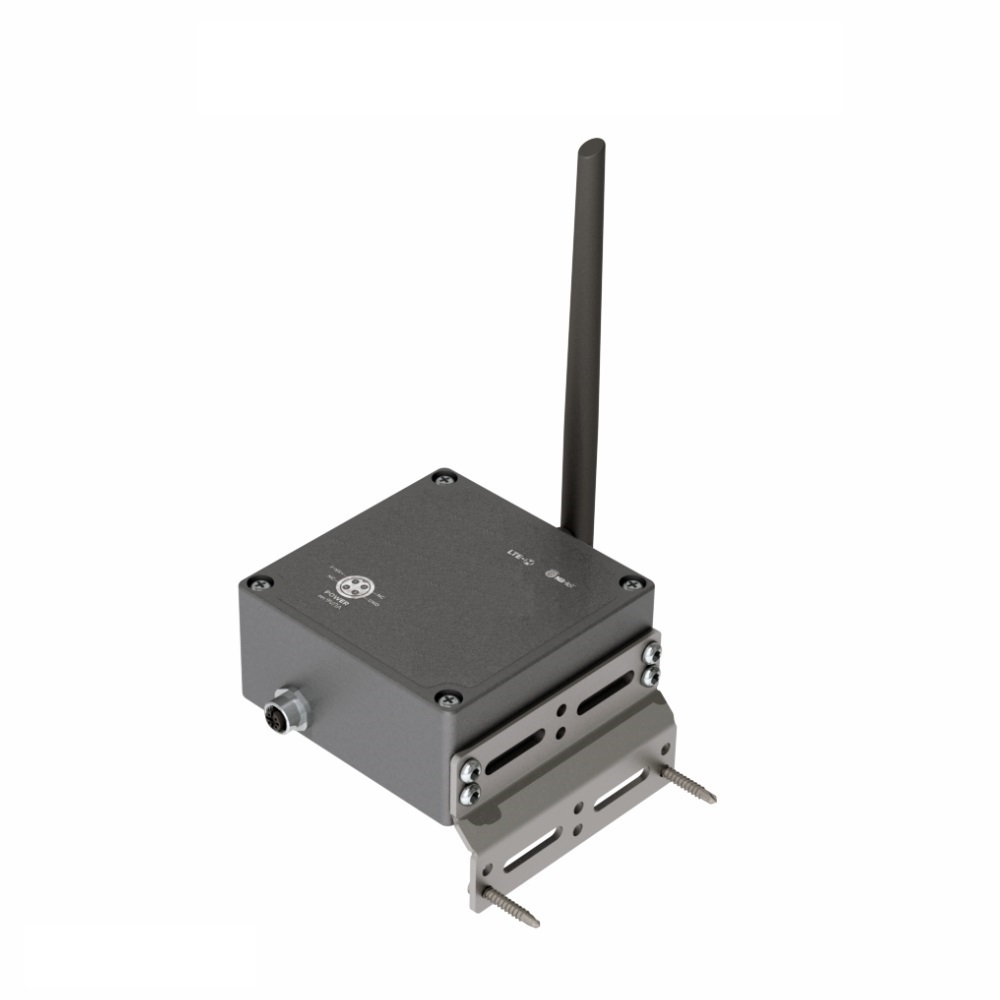
1.1 Introduction
WSNBM-AG, a CATM1/NBIoT tilt sensor, is a device designed to measure X-axis tilt , Y-axis tilt and detect X-axis & Y-axis shock. The sensor includes acceleration& tilt module to measure XY accelerations and measure XY tilts. With the lightweight, efficient communication MQTT protocol, the reliable NBIoT/CATM1 connectivity and the powerful controller, the sensor could measure and transmit real-time tilt data (up to 100 Hz measurement frequency) with minimal overhead. Real-time data from tilt sensors facilitate to identify abnormal tilt of any object such as a Tower, Building, Tree, Electricity Tower, Telecom Tower, Bridges...
1.1.1. The MQTT sensor's system architecture
System components:
- Sensors: publish the data messages to the broker and subscribe request of configuration change messages from the application
- MQTT broker: is the server that receives the data messages from the sensors then route them to the application. In addition, the broker also receives request of configuration change messages from the application and then route them to the sensor
- MQTT application: subscribe the data messages from the sensor and publish request of configuration change messages to the sensor
1.1.2. How to set up the MQTT system?
Please follow these steps:
- Configure on MQTT broker: the user, password, QoS, CA file, SSL
- Configure on the sensor: MQTT configurations (host, port, user, password, CA file, SSL on/off, QoS, message retain), CAT M1/NB-IoT configurations (network category, frequency bands, RAT search sequence)
- Configure on the application: host, port, user, password, QoS, CA file
- Insert the CAT M1/NB-IoT SIM to the sensor, then insert the batteries/power supply. The sensor will publish the messages to the MQTT broker and then the broker will route the messages to the application
1.2 Application Notes
1.2.1. Applications List
Facility Monitoring, Flood Monitoring, Infrastructure Monitoring, Level Monitoring, Machine Health Monitoring, Safety Monitoring, Tilt Monitoring
1.1.2 Application Notes
- This AG tilt sensor measures the static tilt angle of the static object vs. the Gravity direction. Please do not use it for other angle measurements.
- It measures the static tilt angle of stationary objects or slow-moving objects such as Tree, Bridge, Pole, Tower, Crane, and Building...
- It does not measure the tilt angle of a quick-moving object like construction equipment...
1.3 When does device publish the topic?
The device will publish the topic following cases to MQTT brokers:
Case 1: When device is power-up, the device will publish the first topic called START_UP. The payload will tell the user the full device configurations and device health statuses.
Case 2: In every interval time (pre-configured), for example, 24 hours, it will publish the topic called HEARTBEAT. The payload will tell the user the full device configurations and device health statuses.
Case 3: If users want to get the value of device configurations and device health immediately, user could force the device to publish the CONFIG-HEALTH-CHECK topic. The device could be forced by applying the magnet key in more than 5s.
Case 4: During the commissioning, testing, or calibration sensor, the user can force the device to publish the topic to get the data immediately. This topic is called FORCE. The payload will provide data like raw measured value, scaled measured values, and device health. It can be forced by applying the magnet key on the reed switch in 1s;
Case 5: Then, in every interval time (pre-configured), for example, 10 minutes, it will publish the topic called CYCLE. The payload will tell the user the following data like measured values and device health. To change the cycle of data sending, you can change the value of the CYCLE_PERIOD parameter.
Case 6: If XY tit alarms are enable, when difference between average XY tilt for number of samples and corresponding tilt reference are greater or lower than corresponding tilt thresholds during number of sequential readings for alarm on, the device will publish TILT-ALERT topic. In addition, if the alert last more than period of alert cycle, the device will publish next TILT-ALERT topics. The payload contains values of tilts, tilt difference, alert period, alert cycle and the axis causing the alert.
Case 7: If XY acceleration alarms are enable, when XY acceleration for number of samples are greater or lower than corresponding acceleration thresholds during number of sequential readings for alarm on, the device will publish SHOCK-ALERT topic. In addition, if the alert last more than period of alert cycle, the device will publish next SHOCK-ALERT topics. The payload contains values of accelerations, alert period, alert cycle and the axis causing the alert.
Case 8: If the application requests to change device configurations, the application will publish the CONFIG-REQUEST topic to the MQTT broker and the device subscribe the CONFIG-REQUEST topic. After that, the device will change the configuration as request in the CONFIG-REQUEST topic and publish CONFIG-RECEIPT topic. The payload of CONFIG-RECEIPT topic contains the result of the configuration changes.
1.4 Default Configuration
Please refer to the END USER DEFAULT column in the memory map file at the section 1.9 Payload Document and Configuration Tables
1.5 Power Supply
Main power supply
- External Power 7.2-10 VDC, minimum 0.5A required.
Note: The configuration cable must be plugged out the configuration port before supplying the external power
Backup power supply
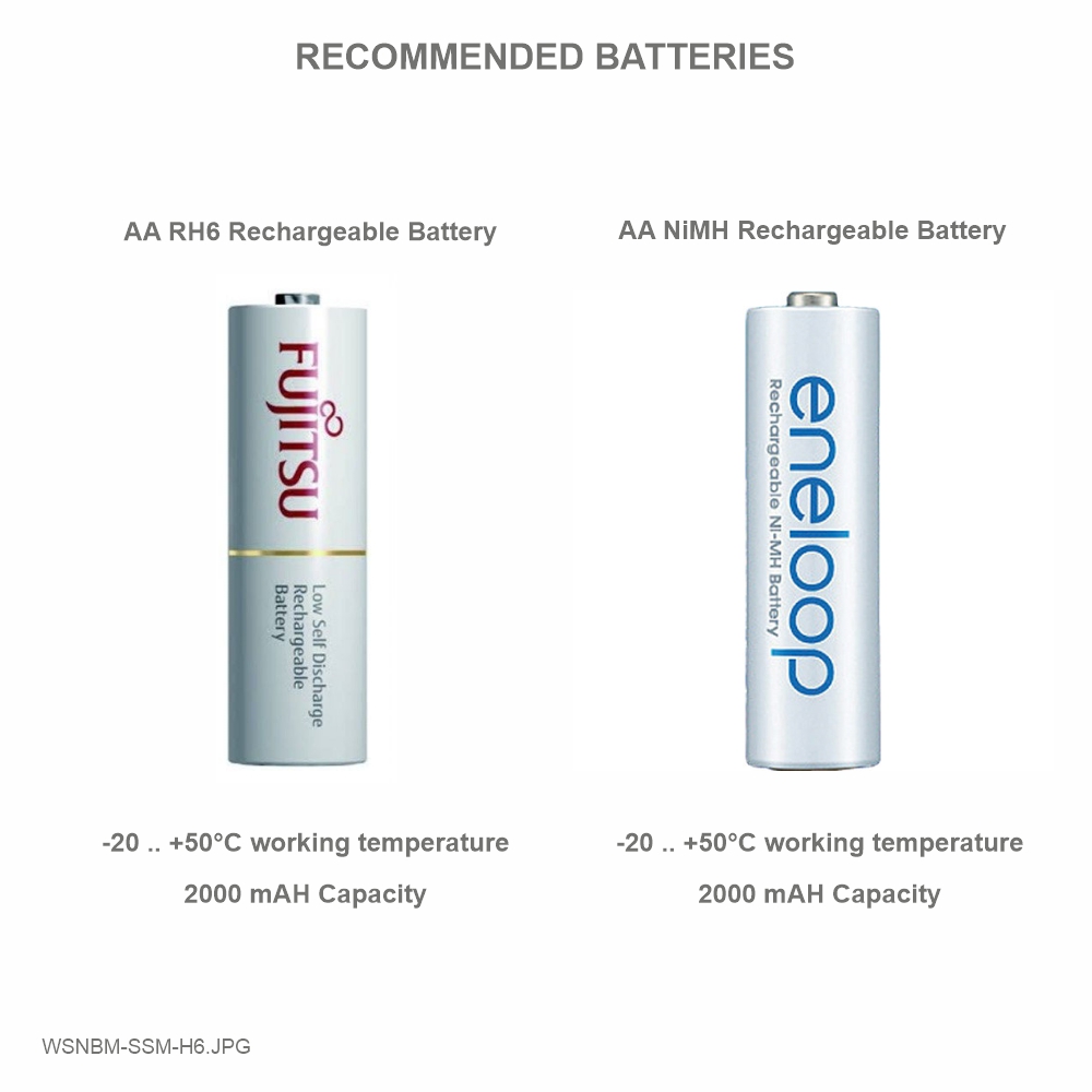
- Rechargeable battery:
- Battery size and Voltage: AA 1.2 VDC
- Number of batteries: 06
- Recommended batteries: Panasonic Eneloop BK-3MCCE or Fujitsu HR-3UTC
Note: The configuration cable must be plugged out the configuration port before inserting the batteries to the device.
Wiring of main power supply to M12 female connector for external power supply
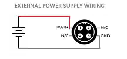
Note:
- Pin 2 and Pin 4 of M12 female connector is not used.
- If the AC adapter is used, isolated AC/DC power adapter is required for interference isolation
- Device housing must be connected to earth plate for safety.
- The configuration cable must be plugged out the configuration port before supplying the external power
Procedures to insert batteries
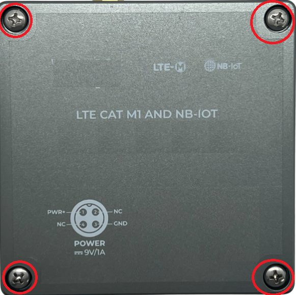
- Open the device upper housing by removing 4 screws
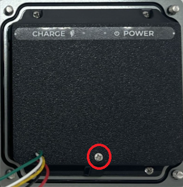
- Open the battery cover by removing a screw
- Insert 6 rechargeable batteries to the battery holder with right polarity
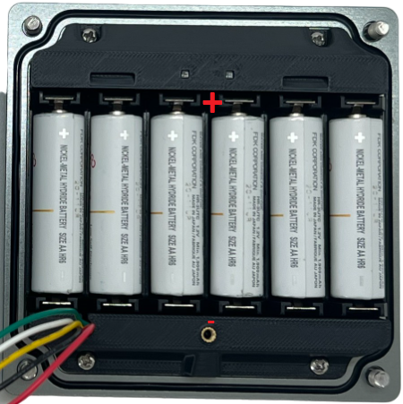
- Close the battery cover and device upper housing
Note:
The configuration cable must be plugged out the configuration port before inserting the batteries.
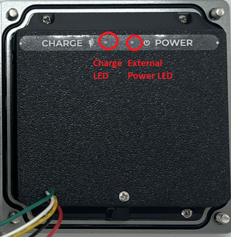
Power LEDs
External Power LED : ON when external power is applied; OFF when no external power is applied
Charge LED: ON when external power supply is greater than 7.2 V to charge the batteries. If the the batteries is fully charged, the LED is OFF.
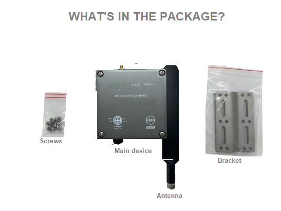
1.6 What's in the Package?
1.7 Guide for Quick Test
The device can be connected quickly to MQTT broker by the following steps.
- MQTT broker's settings: host, post, user, password CAT file (if applicable), QoS
- Cellular settings: CAT M1/NB IoT, frequency bands
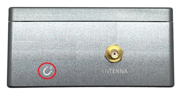
Step 2: Install the antenna to the main device by screwing it clockwise
- Open the device upper housing by removing 4 screws
- Insert the SIM to the device: Push the SIM holder cover slightly, open the SIM holder cover, insert the SIM to the holder, then close the SIM holder cover and then push the SIM holder cover back to origin position. Details as in below video
Step 5: Insert the 6 rechargeable batteries into the device. Please refer section 1.5 Power Supply, sub-section Procedures to insert batteries for details
Step 6: Supply external power 9V minimum 1A to the device
- Plug M12 connector of provided power supply cable to M12 connector on the device
- Plug/Supply external power supply from 9V power adapter or 9V solar panel to power connector of provided power supply cable
Step 7: After supplying the power, the device will publish topics to the MQTT broker. The application subscribes the topics and decode the payload to get measured values. Details of topic name and payload is at Section Section 1.9 Payload Document and Configuration Tables.
1.8 Installation and Wiring
1.8.1 Installation drawings
Dimension drawings for installation as below

1.8.2 Check list for installation
Please follow the checklist below for a successful installation:
1. Have you studied the dimensions of the device as above drawings?
2. Have you tested and make sure the device have been connected successfully as Section "1.7 Guide for Quick Test" above?
3. Have the device been configured properly as per Section 3.2 below?
4. Have the device been calibrated or validated as per Section 3.3 below?
5. Then you can start to install the device at site. Please check the following Installation Notes for Sensor Part (if available) before installation.
1.8.3 Selection for installation location
- Make sure the site is good enough for CAT-M1/NB IoT signals.
- Choose a location far from light, heat, and vibration.
- Select solid barrier to install the sensor.
-
The AG sensor is built-in with the main device.
-
Install device at zero position X tilt of zero and Y tilt of zero
- DO NOT install the sensor or its antenna inside a completed metallic box or housing because the cellular signal can not pass through the metallic wall. The housing is made from Non-metallic materials like plastic, glass, wood, leather, concrete, and cement…is acceptable.
- Attach the sensor housing to a solid barrier using screws.
- Avoid attaching the sensor to soft or vibrating surfaces to prevent false alarms.
- Make sure the site near the power supply if the device use power adapter.
- Make sure the installation location could get enough sun light if the solar panel user solar panel
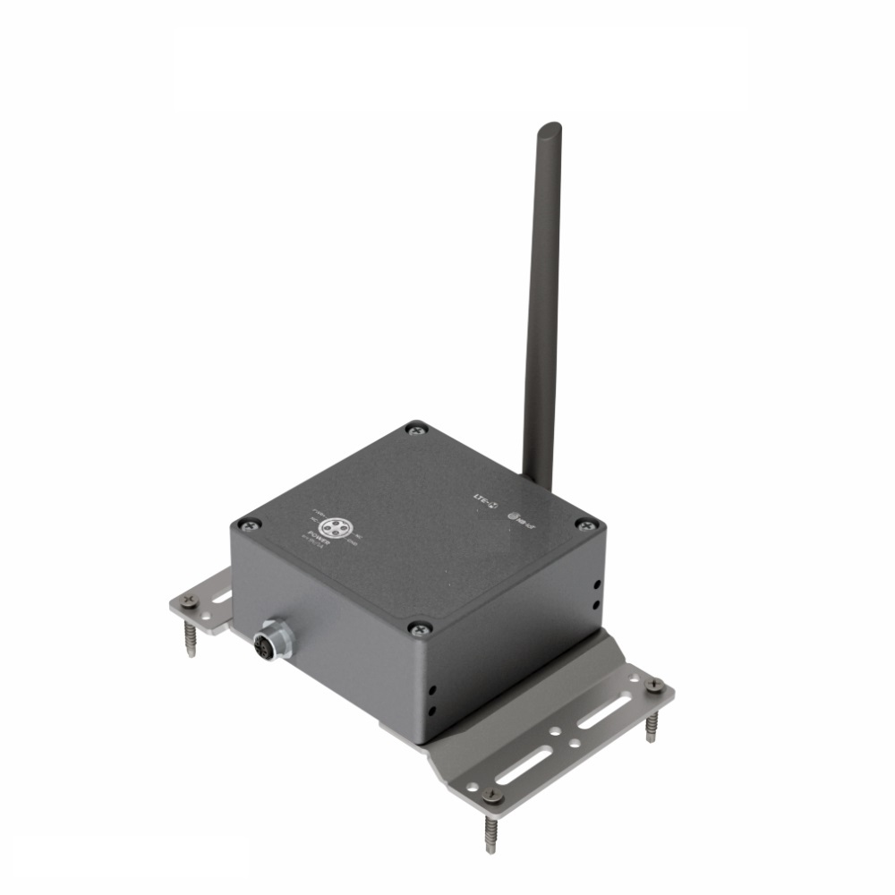
1.8.4 Sample installation
1.9 Payload Document and Configuration Tables
Please click below link for:
-
Payload decoding of Uplink messages;
-
Payload encoding of Downlink messages;
-
Configuration Tables of device.
Click Payload document and configuration table to download Payload Document and Configuration Tables
1.10 How to connect device to MQTT Broker
Please find below the examples of adding Daviteq's MQTT device to the following MQTT broker:
-
Mosquitto MQTT broker
2. Maintenance for WSNBM-AG
2.1 Troubleshooting
Please find below steps to identify the problems from Communication Part or Sensor Part:
- If the device cannot connect to the MQTT broker at the first time, it is the Communication Problem;
- If the device status like battery, RSSI level, data status or other communication is normal, but the measured values are not updated or wrong, it would be the problems of Sensor part;
- If the data coming to MQTT broker is not frequently as expected, the problem would be Communication.
Please refer below the troubleshooting guide for Communication and Sensor Part.
2.1.1. Troubleshooting for Communication
2.1.2. Troubleshooting for Sensor Part (if available)
2.2 Maintenance
3. Advanced guide for WSNBM-AG
3.1 Principle of Operation
Daviteq CAT-M1/NB IoT Seismic Sensor comprises 03 parts linked internally:
• XY acceleration & XY tilt measurement module
• Device controller
• CAT-M1/NB IoT modem
3.1.2. The parameters in published topic name
- SKU: Device SKU, read from DEVICE_SKU parameter in the device memory, max 20 characters, data type of string.
- DEVICE NAME: Device name, read from DEVICE_NAME parameter in device memory, max 20 characters, data type of string.
- DEVICE SN: Device serial number, read from DEVICE_SN parameter in device memory, 20 characters, data type of string.
- DEVICE ALIAS: Device alias, read from DEVICE_ALIAS parameter in device memory, max 20 characters, data type of string.
- TOPIC TYPE: Fixed type of the topic. One of below topic type:
-
- STARTUP
- HEARBEAT
- CONFIG-HEALTH-CHECK
- FORCE
- CYCLE
- TILT-ALERT
- SHOCK-ALERT
- CONFIG-RECEIPT
- STARTUP
3.1.3. Primary output values in the payload of published topics
- Sampled Average X-Axis Tilt : Average X-axis tilt during the number of sample, unit of degree. This parameter is sampleAvgXTilt in the published topic's payload.
- Sampled Minimum X-Axis Tilt : Minimum X-axis tilt during the number of sample, unit of degree. This parameter is sampleMinXTilt in the published topic's payload.
- Sampled Maximum X-Axis Tilt : Maximum X-axis tilt during the number of sample, unit of degree. This parameter is sampleMaxXTilt in the published topic's payload.
- Sampled Average Y-Axis Tilt : Average Y-axis tilt during the number of sample, unit of degree. This parameter is sampleAvgYTilt in the published topic's payload.
- Sampled Minimum Y-Axis Tilt : Minimum Y-axis tilt during the number of sample, unit of degree. This parameter is sampleMinYTilt in the published topic's payload.
- Sampled Maximum Y-Axis Tilt : Maximum Y-axis tilt during the number of sample, unit of degree. This parameter is sampleMaxYTilt in the published topic's payload.
- Cycle Average X-Axis Tilt : Average X-axis tilt during a cycle, unit of degree. This parameter is cycleAvgXTilt in the published topic's payload.
- Cycle Minimum X-Axis Tilt : Minimum X-axis tilt during a cycle, unit of degree. This parameter is cycleMinXTilt in the published topic's payload.
- Cycle Maximum X-Axis Tilt : Maximum X-axis tilt during a cycle, unit of degree. This parameter is cycleMaxXTilt in the published topic's payload.
- Cycle Average Y-Axis Tilt : Average Y-axis tilt during a cycle, unit of degree. This parameter is cycleAvgYTilt in the published topic's payload.
- Cycle Minimum Y-Axis Tilt : Minimum Y-axis tilt during a cycle, unit of degree. This parameter is cycleMinYTilt in the published topic's payload.
- Cycle Maximum Y-Axis Tilt : Maximum Y-axis tilt during a cycle, unit of degree. This parameter is cycleMaxYTilt in the published topic's payload.
- X-Axis Tilt Difference: Difference between sampleAvgXTilt and referenceXTilt, unit of degree. This parameter is xTiltDifference in the published topic's payload.
- Y-Axis Tilt Difference: Difference between sampleAvgYTilt and referenceYTilt, unit of degree. This parameter is yTiltDifference in the published topic's payload.
- X-Axis Tilt Alert Status: X-axis tilt alert status (high, low, none). This parameter is xTiltAlertStatus in the published topic's payload.
- X-Axis Tilt Alert Period: Period of X-axis tilt alert, unit in millisecond. This parameter is xTiltAlertPeriod in the published topic's payload.
- X-Axis Tilt Alert Cycle Number: Number of X-axis tilt alert cycle. This parameter is xTiltAlertCycleNumber in the published topic's payload.
- Y-Axis Tilt Alert Status: Y-axis tilt alert status (high, low, none). This parameter is yTiltAlertStatus in the published topic's payload.
- Y-Axis Tilt Alert Period: Period of Y-axis tilt alert, unit in millisecond. This parameter is yTiltAlertPeriod in the published topic's payload.
- Y-Axis Tilt Alert Cycle Number: Number of Y-axis tilt alert cycle. This parameter is yTiltAlertCycleNumber in the published topic's payload.
- Measured X-Axis Acceleration: Measured X-axis acceleration, unit of mG. This parameter is measureXAcceleration in the published topic's payload.
- Measured Y-Axis Acceleration: Measured Y-axis acceleration, unit of mG. This parameter is measureYAcceleration in the published topic's payload.
- X-Axis Acceleration Alert Status: X-axis acceleration alert status (high, low, none). This parameter is xAccelerationAlertStatus in the published topic's payload.
- X-Axis Acceleration Alert Period: Period of X-axis acceleration alert, unit in millisecond. This parameter is xAccelerationAlertPeriod in the published topic's payload.
- X-Axis Acceleration Alert Cycle Number: Number of X-axis acceleration alert cycle. This parameter is xAccelerationAlertCycleNumber in the published topic's payload.
- Y-Axis Acceleration Alert Status: Y-axis acceleration alert status (high, low, none). This parameter is yAccelerationAlertStatus in the published topic's payload.
- Y-Axis Acceleration Alert Period: Period of Y-axis acceleration alert, unit in millisecond. This parameter is yAccelerationAlertPeriod in the published topic's payload.
- Y-Axis Acceleration Alert Cycle Number: Number of Y-axis acceleration alert cycle. This parameter is yAccelerationAlertCycleNumber in the published topic's payload.
3.1.4. Secondary output values in the payload of published topics
Below output values are useful for device maintenance and troubleshooting.
- Device Configurations: Full configuration of the device, hexadecimal. The configuration from address 4096 (decimal) and the length of 501 register (2004 hexadecimal value). This parameter is fullConfigurationString in the published topic's payload.
- Cellular Network Category: Cellular service mode (GSM/GPRS/EDGE/eMTC(CATM1), NB-IoT). This parameter is cellularServiceMode in the published topic's payload.
- RSSI: Received CAT-M1/NB IoT signal strength indicator, unit of dB. This parameter is RSSI in the published topic's payload.
- RSRP: Reference CAT-M1/NB IoT signal received power, unit of dB. This parameter is RSRP in the published topic's payload.
- SINR: CAT-M1/NB IoT signal to interference plus noise ratio. This parameter is SINR in the published topic's payload.
- RSRQ: Reference CAT-M1/NB IoT signal received quality, unit of dB. This parameter is RSRQ in the published topic's payload.
- MCU Temperature: MCU temperature, unit of degree. This parameter is mcuTemperature in the published topic's payload.
- Power Source: Status of device's power supply (on/off).
ON: device is powered directly by external power
OFF: device is powered by chargeable batteries. This parameter is powerSupplyStatus in the published topic's payload. - Configuration Start Address: Start address of the changed configuration, in decimal. This parameter is startAddress in the published topic's payload.
- Configuration Register Length: Register number of changed configuration, in decimal, max = 400 hexadecimal values. This parameter is registerLength in the published topic's payload.
- Configuration Requested Value: Requested value for the configuration change, in hexadecimal. If the value of startAddress or value of startAddress + registerLength are in Read Only area OR out of device memory map's range OR if the requestedValue does not match to registerLength or hexadecimal value, the requestedValue will be assigned to "FFFF". This parameter is requestedValue in the published topic's payload.
- Configuration Requested Validity: Validity of configuration's change request (Valid, Invalid). This parameter is requestValidity in the published topic's payload.
- Configuration Changed Value: If the change request is valid, the device configuration will be changed as request and changedValue will equal requestedValue. If the change request is invalid, the device configuration will NOT be changed, and the changedValue will be old value in hexadecimal value. If the value of startAddress or value of startAddress + registerLength are in Read Only area OR out of device memory map's range OR if the requestedValue does not match to registerLength or hexadecimal value, the requestedValue will be assigned to "FFFF". This parameter is changedValue in the published topic's payload.
3.1.5. The parameters in subscribed topic name
- SKU: Device SKU, read from DEVICE_SKU parameter in the device memory, max 20 characters, data type of string.
- DEVICE NAME: Device name, read from DEVICE_NAME parameter in device memory, max 20 characters, data type of string.
- DEVICE SN: Device serial number, read from DEVICE_SN parameter in device memory, 20 characters, data type of string.
- DEVICE ALIAS: Device alias, read from DEVICE_ALIAS parameter in device memory, max 20 characters, data type of string.
- TOPIC TYPE: Fixed type of the topic. The topic type is CONFIG-REQUEST, a request to change the parameter.
3.1.6. Parameters in the payload of subscribed topic name
- Subscribed Topic Type: Fixed type of the topic is CONFIG-REQUEST. This parameter is topicType in the published topic's payload.
- Epoch Time: Topic's Epoch Time format, unit of millisecond. This parameter is epochTime in the published topic's payload.
Device Serial Number: Device serial number. This parameter is deviceSerialNumber in the published topic's payload. - Start Address: Start address of the changed configuration, in decimal. This parameter is startAddress in the published topic's payload.
- Register Length: Register number of changed configuration, in decimal, max length = 400 hexadecimal value. This parameter is registerLength in the published topic's payload.
- Requested Value: Requested value for the configuration change, in hexadecimal. The length must be 4 hexadecimal values for 1 register, 8 hexadecimal values for 2 registers. This parameter is requestedValue in the published topic's payload.
3.1.7. Device operation principle description
The device measures the value of X/Y tilt every MEASUREMENT_CYLCE (Maximum MEASUREMENT_CYLCE is 10 milliseconds (100 Hz)). Based on tilt measured value, the device calculates moving (rolling) AVG, MIN, MAX during corresponding NUM_OF_NUMBER and the results are sampleAvgXTilt, sampleAvgYTilt, sampleMinXTilt, sampleMinYTilt, sampleMaxXTilt, sampleMaxYTilt parameters.
If difference between sampleAvgXTilt/sampleAvgYTilt and referenceXtilt/referenceYtilt are greater than corresponding DIFFERENCE_AVG_TILT_HIGH_ALARM_THRESHOLD or are less than DIFFERENCE_AVG_TILT_LOW_ALARM_THRESHOLD during corresponding SEQUENCE_NUM_FOR_HI_ALARM_ON, the device will publish first TILT-ALERT topic and TILT_ALARM_FLAG will be set to 1. During TILT_ALARM_PERIOD (fastest 1 minute) since first alarm, if difference between sampleAvgXTilt/sampleAvgYTilt and referenceXtilt/referenceYtilt return to the normal range during corresponding SEQUENCE_NUM_FOR_TILT_ALARM_OFF, the TILT_ALARM_FLAG will be set to 0. After TILT_ALARM_PERIOD, if TILT_ALARM_FLAG=1, the device will publish the second TILT-ALERT topic. The device handle tilt alarms for sampleAvgXTilt, sampleAvgYTilt separately. referenceXtilt/referenceYtilt are the values of sampleAvgXtilt/sampleAvgYtilt when SET_REF_POS_FOR_TILT_ALARM is set to 1. DIFFERENCE_AVG_TILT_HIGH_ALARM_THRESHOLD must be greater than DIFFERENCE_AVG_LOW_ALARM_THRESHOLD.
The device measures the value of X/Y accelerations every MEASUREMENT_CYLCE (Maximum MEASUREMENT_CYLCE is 10 milliseconds (100 Hz)) and the results are measureXAcceleration, measureYAcceleration parameters. If measureXAcceleration/measureYAcceleration are greater than corresponding ACCELERATION_HIGH_ALARM_THRESHOLD or less than corresponding ACCELERATION_LOW_ALARM_THRESHOLD during corresponding SEQUENCE_NUM_FOR_ACCELERATION_ALARM_ON, the device will publish first SHOCK- ALERT topic and ACCELERATION_ALARM_FLAG will be set to 1. During ACCELERATION_ALARM_PERIOD (fastest 1 minute) since first alarm, if measureXAcceleration/measureYAcceleration return to the normal acceleration range during corresponding SEQUENCE_NUM_FOR_ACCELERATION_ALARM_OFF, the ACCELERATION_ALARM_FLAG will be set to 0. After ACCELERATION_ALARM_PERIOD, if ACCELERATION_ALARM_FLAG=1, the device will publish the second SHOCK-ALERT topic. The device handle acceleration alarms for measureXAcceleration, measureYAcceleration separately.
The device publishes TILT alert, ACCELERATION alert, startup, heartbeat, config health check, force, cycle topic and config receipt topics. The sensor publishes the heartbeat topic, and cyclic data topic (fastest 1 minute) regularly. When the device is powered up, it publishes the startup topic. When the device is forced by magnetic key within 1 second the device publishes the force topic. When the device is forced by magnetic key within 5 second the device publishes the config health check topic. After the device subscribes to the config change request topic from the application, the device will publish the config receipt topic. When tilt/acceleration alert occurs, the device publishes corresponding alert topics.
The startup, heartbeat, the config health check topic contains information of current full configurations, and device health information. The force data topic contains information of device health information and Avg/Min/Max measured tilt during NUM_OF_SAMPLE. The cycle data contains information of device health information and measured Avg/Min/Max Tilt during a cycle. Config receipt topic includes configuration parameter address, the configuration parameter length, request to change configuration value, and changed configuration value.
Tilt alert topic includes information of sampleAvgX/YTilt, alert axis(X,Y), alert status (high, low none), alert period, number of alert cycle. Acceleration alert topic contains information of measureX/Yacceleration, alert axis, alert status (high, low, none), alert period, number of alert cycle.
1.3.8 Configuration for tilt alarm
Follow below steps to configure tilt alarm:
Step 1:
Enable alarm for X-axis tilt via offline or online :
- DIFFERENCE_AVG_X_TILT_ALARM_ENABLE = 1 to enable alarm
Chang the relevant settings for below configurations:
- DIFFERENCE_AVG_X_TILT_ALARM_PERIOD
- DIFFERENCE_AVG_X_TILT_HI_ALARM_THRESHOLD
- DIFFERENCE_AVG_X_TILT_SEQ_NUM_FOR_HI_ALARM_ON
- DIFFERENCE_AVG_X_TILT_SEQ_NUM_FOR_HI_ALARM_OFF
- DIFFERENCE_AVG_X_TILT_LOW_ALARM_THRESHOLD
- DIFFERENCE_AVG_X_TILT_SEQ_NUM_FOR_LOW_ALARM_ON
- DIFFERENCE_AVG_X_TILT_SEQ_NUM_FOR_LOW_ALARM_OFF
Refer the memory map at section 1.9 Payload Document and Configuration Tables for meaning of these configurations
Enable alarm for Y-axis tilt via offline or online :
- DIFFERENCE_AVG_X_TILT_ALARM_ENABLE = 1 to enable alarm
Change the relevant settings for below configurations:
- DIFFERENCE_AVG_Y_TILT_ALARM_PERIOD
- DIFFERENCE_AVG_Y_TILT_HI_ALARM_THRESHOLD
- DIFFERENCE_AVG_Y_TILT_SEQ_NUM_FOR_HI_ALARM_ON
- DIFFERENCE_AVG_Y_TILT_SEQ_NUM_FOR_HI_ALARM_OFF
- DIFFERENCE_AVG_Y_TILT_LOW_ALARM_THRESHOLD
- DIFFERENCE_AVG_Y_TILT_SEQ_NUM_FOR_LOW_ALARM_ON
- DIFFERENCE_AVG_Y_TILT_SEQ_NUM_FOR_LOW_ALARM_OFF
Refer the memory map at section 1.9 Payload Document and Configuration Tables for meaning of these configurations
Step 2:
Install the device at site
Step 3:
Write SET_REF_POS_FOR_TILT_ALARM =1 online or offline to set the current position as reference position to detect tilt alarm. After finishing, this setting will be back to 0 automatically. The alarm will be triggered based on the difference between the sampled tilts and referenced tilts.
3.1.9 Calibration for tilt
The tilt sensor is calibrated at 3 calibration positions:
1. X tilt and Y tilt equal 0 degrees.
2. X tilt equals +90 degrees.
3. Y tilt equals +90 degrees.
After fixing the device at above positions, please write the TILT_CALIB_ENABLE to 1 by offline or online (downlink ) to calibrate the sensor. After finishing, TILT_CALIB_ENABLE will be back to 0 automatically.
3.1.10 Offset the tilt value
Enable to offset X tilt and Y tilt value at current position to 0 degrees by set OFFSET_TILT_ENABLE to 1. After finishing, this value will be back to 0 automatically. The offset function could be canceled by set OFFSET_TILT_ENABLE to 2. After finishing, this value will be back to 0 automatically.
Please check the Payload document to understand clearly about uplink messages, downlink messages, meaning of parameters for configuration...
3.2 Configuration
3.2.1. How to configure the device?
Sensor configuration can be configured in 02 methods:
Method 1: Online configuring via Subscribing CONFIG-REQUEST topic from MQTT Application.
Method 2: Offline configuring via Offline cable.
3.2.2 Which Parameters are configured?
Please check Part E. MEMORY MAP in Section 1.9 Payload Documents above.
3.2.3 Online configuring via subscribing CONFIG-REQUEST topic from MQTT Application.
Please refer Part C. SUBSCRIBE TOPIC in Section 1.9 Payload Documents above.
3.2.4 Offline configuring via Offline cable.
Please download the Configuration Template File of this sensor to be used in Step 4 below.
Click Download CSV file to download the Configuration Template File
Instructions for offline configuration of the Seismic sensors. Please follow the following steps.
Prepare equipment and tools
The following items must be prepared for configuration.
- A PC using the Windows OS (Windows 7 or above versions). The PC installed the COM port driver of the Modbus configuration cable (if needed). The driver is at link: Modbus Configuration Cable COM port driver for PC and the instruction to install the driver at link: How to install the driver.
- A Modbus configuration cable
- A M12-CAB-CONFIG cable
Download and launch Modbus configuration software
-
Click the link below to download Modbus configuration software:
Click Modbus configuration software to download the software
After downloading the software, unzip the file named Modbus Configuration.zip and then copy the extracted folder to the storage drive for long-term use.
-
Open the folder, double click on the file Modbus Configuration Tool Version.exe to launch the software and the software interface as below:
Note: The software only runs on Microsoft Windows OS (Windows 7 and above)
Connect the cable and configure the sensor
Step 1:
Connect the PC to the Battery Pack using the configuration cable and converter cable
- Use the configuration cable (Item code: TTL-LRW-USB-01).
- Connect the USB-A plug into the USB-A socket of the PC.
Step 2:
On the configuration software, choose the relevant Port (the USB port which is the cable plugged in) and set the BaudRate: 115200, Parity: none
Step 3:
Step 4:
Import the configuration template file of the sensor (as above link) to the software: click menu File/ Import New and then browse the relevant sensor template file (csv file) and click Open to import the template file.
Each sensor type has its own template file. Refer to the sensor's manual to download the correct file.
Step 5: Open the housing of the sensor and quickly plug the connector of the configuration cable into sensor's modbus configuration port. After plugging the connector, the software will read the parameter values automatically.
 - Open the housing of the sensor. |
.jpg) - Plug the cable connector into sensor's Modbus configuration port. Note: this port is located at a different location, depends on the sensor type |
Step 6: Read the current value of the parameter with function 3
- At the relevant row of the parameter, check box 3 on column FC to read the value of the parameter. The read value is shown on VALUE ON MEMMAP column.
Step 7: Write the new setting to the parameter with function 16
- Double click on the column VALUE TO WRITE of the parameter and input the new setting of the parameter
- Uncheck the tick on the FC column of the parameter, click on the arrow, select 16 and then check on the FC column to write a new setting to the parameter. The WRITE_OK text will show on EXCEPTION column if the software successfully writes the setting.
- Repeat step 6 to read the setting of the parameter for checking.
For some critical parameters of the sensor, the password in "password for setting" must be written before writing the new settings to these parameters.
Only read/write registers are allowed to write.
Troubleshooting of offline configuration
| No. | Phenomena | Reason | Solution |
|---|---|---|---|
| 1 | The status on the software always shows Disconnected although the configuration cable is connected to the PC | The selected COM port is incorrect | Select the correct COM port to which the configuration cable connects to PC |
| The configuration cable is defective | Check the configuration cable | ||
| 2 | The software reads no value after importing the right template and connecting the right cable. | The cable is defective or lost connection | Check or replace the new configuration cable |
| The USB port is defective | Check USB port | ||
| There is no power supply to the sensor via configuration cable | Check the power line of the cable | ||
| The sensor or sensor port is defective | Check the sensor and sensor port | ||
| 3 | No COM port appears in the Port list | No configuration cable is plugged into the PC | Plug the cable to the PC |
| The cable driver is not installed on the PC | Install the driver for the PC | ||
| 4 | The parameter table on the software is empty | The template file has not been imported | Click menu File and sub-menu Import New to import the template file |
| 5 | The parameter table on the software does NOT match the memory map table of the sensor. | The wrong template file was imported. | Go to the correct manual page of the product and download the right template file, then import the template file into the software. |
3.3 Calibration/ Validation
3.3.1 How to force sensor to send data for calibration
The device can be triggered to send data to the gateway immediately by using the magnetic key to touch the reed switch point on the housing within 1 second as below figures:

Note:
Upon transmitting the data to the gateway using the magnetic key, the timer for the transmission time interval will be reset.
The minimum time interval between two manual triggers is 15 seconds. If the interval is less than 15 seconds, data transmission will not occur.
3.3.2 Calibration for tilt
The tilt sensor is calibrated at 3 calibration positions:
1. X tilt and Y tilt equal 0 degrees.
2. X tilt equals +90 degrees.
3. Y tilt equals +90 degrees.
After fixing the device at above positions, write the TILT_CALIB_ENABLE to 1 by offline or online to calibrate the sensor. After finishing, TILT_CALIB_ENABLE will be back to 0 automatically.
4. Product Specifications for WSNBM-AG
4.1 Specifications
| MEASUREMENT | |
| Tilt Sensor | Built-in advanced accelerometer to deliver tilt angle measurement of XY |
| Tilt Measurement range | ±90° |
| Tilt Resolution | ±0.001° |
| Tilt Repeatability | ±0.010° |
| Sensor sampling rate | 100Hz max |
| COMMUNICATION | |
| Host connectivity | CAT-M1/NB IoT Global Bands |
| Antenna | External antenna |
| Protocol | MQTT, JSON payload |
| Data sending modes | interval time, alarm and manually triggering by magnetic key |
| Alarm function | for tilt and acceleration |
| Power Supply | External power 5-10V 1A minimum for main power and 6xAA rechargeable battery 1.2V/2000mAh (recommend Panasonic Eneloop Standard) for auxiliary power, M12 connector |
| Ambient working temperature | -40 .. 85℃ (depends on battery specification) |
| Housing | Anodized A6061 Aluminum, Carbon-color, IP67 |
| Bracket | :2 x 304SS Bracket for base mount or wall mount |
| Size | Net weight | H110xW110xD53 (not including antenna)/ 850g |
| Mounting type | Wall mount |
5. Warranty for WSNBM-AG
5.1 Warranty
Below terms and conditions are applied for products manufactured and supplied by the Supplier.
5.1.1 Free Warranty Conditions
- The manufacturer undertakes to guarantee within 12 months from shipment date.
- Product failed due to defects in material or workmanship.
- Serial number, label, warranty stamp remains intact (not purged, detected, edited, scraped, tore, blurry, spotty, or pasted on top by certain items).
- During the warranty period, if any problem of damage occurs due to technical manufacturing, please notify our Support Center for free warranty consultancy. Unauthorized treatments and modifications are not allowed.
- Product failed due to the defects from the manufacturer, depending on the actual situation, Supplier will consider replacement or repairs.
Note: One way shipping cost to the Return center shall be paid by Customers.
5.1.2 Paid Warranty
- The warranty period has expired.
- The product is not manufactured by the Manufacturer.
- Product failed due to damage caused by disasters such as fire, flood, lightning or explosion, etc.
- Product damaged during shipment.
- Product damaged due to faulty installation, usage, or power supply.
- Product damage caused by the customer.
- Product rusted, stained by effects of the environment or due to vandalism, liquid (acids, chemicals, etc.)
- Product damage is caused by unauthorized treatments and modifications.
Note: Customers will be subjected to all repairing expenses and 2-way shipping costs. If arises disagreement with the company's determining faults, both parties will have a third party inspection appraise such damage and its decision be and is the final decision.