Manual for Sigfox sensors - Common parts
- What is Sigfox?
- Troubleshooting for Sigfox Communication
- Offline configuration for Sigfox Sensors
- List of Configuration template files of Sigfox-Ready Sensors
- Common notes in installation of Sigfox-Ready Sensors
What is Sigfox?
Understanding the Sigfox Connectivity Technologies.
Please find this link for understanding Sigfox Connectivity Technologies.
Troubleshooting for Sigfox Communication
This is the troubleshooting for Sigfox communication of Sigfox-ready sensors with FW versions listed below:
| No. | Phenomena | Reason | Solutions |
| 1 | Node does not send RF to the base station periodically, LED does not blink |
|
|
| 2 | Node does not send RF to the base station according to the alarm, LED does not blink |
|
|
| 3 | Node does not send RF to the base station when activated by the magnetic switch, LED does not blink |
|
|
| 4 | Node has blinked LED when sending RF but the base station cannot receive |
|
|
| 5 | Node has sent RF but the LED does not blink |
|
|
| 6 | The node does not send RF and the RF module is hot |
|
|
| 7 | RSSI is weak and often loses data |
|
|
| 8 | The measurement values from the sensor do not change and keep constant values for a long time |
|
|
Offline configuration for Sigfox Sensors
THIS IS OBSOLETE MANUAL
Please access https://www.iot.daviteq.com/wireless-sensors for updated manual
Instructions for offline configuration of the Daviteq Sigfox-Ready sensors. Please follow the following steps.
Note: THE SENSOR IS ONLY ACTIVE FOR CONFIGURATION IN THE FIRST 60 SINCE POWER UP BY BATTERY OR PLUGGING THE CONFIGURATION CABLE.
1. Prepare equipment and tools
The following items must be prepared for configuration.
- A PC using the Windows OS (Win7 or above versions). The PC is installed with the COM port driver of the Modbus configuration cable (if needed). The driver is at link: Modbus Configuration Cable COM port driver for PC and the instruction to install the driver at link: How to install the driver
- A Modbus configuration cable;
- Tools to open the housing of Sigfox-ready sensors (L hex key or screwdriver)
2. Download and launch Daviteq Modbus configuration software
- Click the link below to download Daviteq Modbus configuration software:
https://filerun.daviteq.com/wl/?id=yDOjE5d6kqFlGNVVlMdFg19Aad6aw0Hs
- After downloading the software, unzip the file named: Daviteq Modbus Configuration Tool.zip and then copy the extracted folder to the storage drive for long-term use.
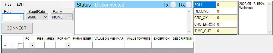
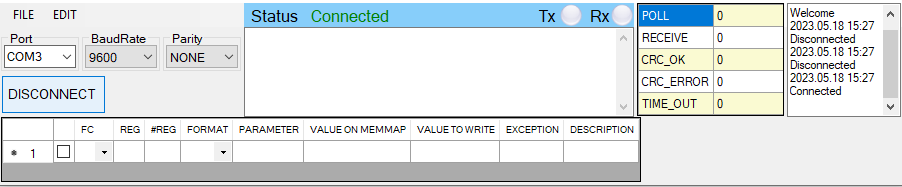
- Open the folder, double click on the file Daviteq Modbus Configuration Tool Version.exe to launch the software and the software interface as below:
Note: The software only runs on Microsoft Windows OS (win7 and above).
3. Connect the cable and configure the sensor
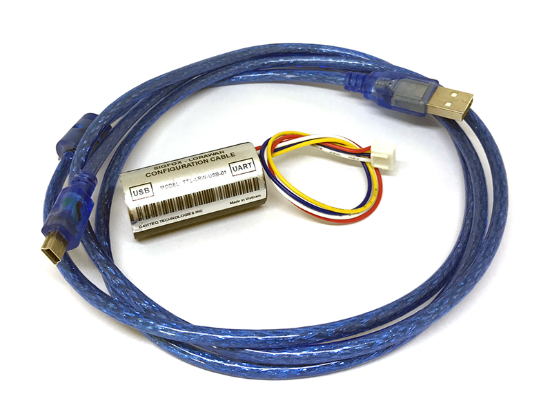
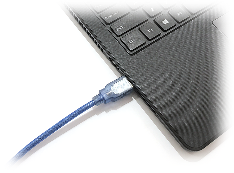
Step 1: Connect USB plug of Modbus configuration cable to USB socket of the PC
|
- Use the configuration cable (Item code: TTL-LRW-USB-01). |
- Connect the USB-A plug into the USB-A socket of the PC |
Step 2: On the configuration software, choose the relevant Port (the USB port which is the cable plugged in) and set the BaudRate: 9600, Parity: none
Step 3: Click the “ Connect “ button to connect the software to the sensor. After a successful connection, the connected status(green text) will show on the software.
Step 4: Import the configuration file for the sensor to the software: click menu File/ Import New and then browse the relevant sensor template file (csv file) and click Open to import the template file.
Each sensor type has its own template file. Refer to the sensor's manual to download the correct file.
The sensor is only active for configuration for 60 seconds since plugging the configuration cable or the power supply into the sensor.
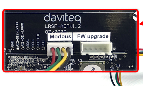
Step 5: Open the housing of the sensor and quickly plug the connector of the configuration cable into sensor's modbus configuration port. After plugging the connector, the software will read the parameter values automatically.
|
- Open the housing of the sensor. |
- Plug the cable connector into sensor's modbus configuration port. Note: this port is located at a different location, depends on the sensor type |

The sensor is only active for configuration for 60 seconds since plugging the configuration cable or the power supply into the sensor.
Step 6: Read the current value of the parameter with function 3
- At the relevant row of the parameter, check box 3 on column FC to read the value of the parameter. The read value is shown on VALUE ON MEMMAP column.
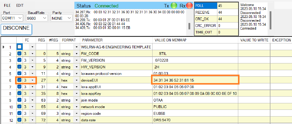
The sensor is only active for configuration for 60 seconds since plugging the configuration cable or the power supply into the sensor. After 60 seconds, the TIME_OUT text will show on EXCEPTION column of the software.
Step 7: Write the new setting to the parameter with function 16
- Double click on the column VALUE TO WRITE of the parameter and input the new setting of the parameter
- Uncheck the tick on the FC column of the parameter, click on the arrow, select 16 and then check on the FC column to write a new setting to the parameter. The WRITE_OK text will show on EXCEPTION column if the software successfully writes the setting.
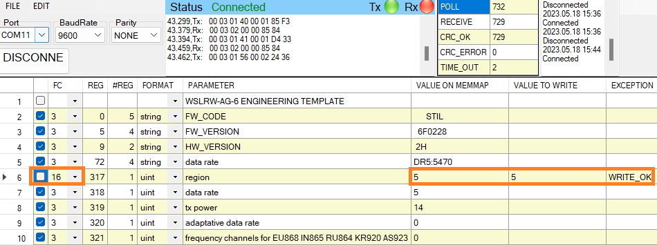
- Repeat step 6 to read the setting of the parameter for checking.
The sensor is only active for configuration for 60 seconds since plugging the configuration cable or the power supply into the sensor. After 60 seconds, the TIME_OUT text will show on EXCEPTION column of the software.
For some critical parameters of the sensor, the password in "password for setting" must be written before writing the new settings to these parameters.
Only read/write registers are allowed to write.
4. Troubleshooting
|
No. |
Phenomena |
Reason |
Solutions |
|
1 |
The status on the software always shows Disconnected although the configuration cable is connected to the PC |
|
|
|
2 |
The software reads no value after importing the right template and connecting the right cable. |
|
|
|
3 |
No COM port appears in the Port list |
|
|
|
4 |
The parameter table on the software is empty |
|
|
|
5 |
The parameter table on the software does NOT match the memory map table of the sensor. |
|
|
5. List of Configuration Template Files for various Sigfox-Ready Sensors
Please find this link for the template file of each Sigfox-Ready sensor.
END.
List of Configuration template files of Sigfox-Ready Sensors
THIS IS OBSOLETE MANUAL
Please access https://www.iot.daviteq.com/wireless-sensors for updated manual
Each Sigfox-Ready Sensor has a template file for Offline configuration. Please find below the list.
| SKU# | Product Description | FW Ver. | Link to download Configuration Template File | Remarks |
| WSSFC-AC | Sigfox-Ready AC Current Sensor | 1.0 | Template file for WSSFC-AC-FW 1.0-HW 1.0 | |
| WSSFC-AC | Sigfox-Ready AC Current Sensor | 3.0 | Template file for WSSFC-AC-FW 3.0 | |
| WSSFC-AG | Sigfox-Ready Accelerometer-Gyro Sensor | 1.0 | Template file for WSSFC-AG-FW 1.0- HW 1.0 | |
| WSSFC-ATH | Sigfox-Ready integrated ambient humidity and temperature sensor | 1.0 | Template file for WSSFC-ATH-FW 1.0- HW 1.0 | |
| WSSFC-CAP10 | Sigfox-Ready high precision capacitance fuel level sensor | 1.0 | Template file for WSSFC-CAP10-FW 1.0 HW 1.0 | |
| WSSFC-CO2 | Sigfox-Ready Industrial CARBON DIOXIDE GAS SENSOR, NDIR Type | 1.0 | Template file for WSSFC-CO2-FW 1.0- HW 1.0 | |
| WSSFC-LPC | Sigfox-Ready People counter, Lidar technology | 1.0 | Template file for WSSFC-LPC-FW 1.0- HW 1.1 | |
| WSSFC-LPC | Sigfox-Ready People counter, Lidar technology | 2.0 | Template file for WSSFC-LPC-FW 2.0- HW 2.0 | |
| WSSFC-G4F-NH3 | Sigfox-Ready Gas Sensor, 4-Seri, Ceiling mount type, NH3 | 6.0 | Template file for WSSFC-NH3-FW 6.0-HW 2.0 | |
| WSSFC-PPS | Sigfox-Ready Process Pressure Sensor | 1.0 | Template file for WSSFC-PPS-FW 1.0- HW 1 | |
| WSSFC-ULC | Sigfox-Ready Ultrasonic level sensor for liquid or flat surface | 1.2 | Template file for WSSFC-ULC-FW 1.2- HW 1.1 | |
| WSSFC-V1A | Sigfox-Ready Single Axis Vibration Sensor, 10 KHz Piezo technology | 1.0 | Template file for WSSFC-V1A-FW 1.0- HW 1.1 | |
| WSSFCEX-PPS | Sigfox-Ready Process Pressure Sensor with Exd approval | 1.01 | Template file for WSSFCEX-PPS-FW 1.01-HW 1.0 | |
| WSSFCEX-GHC |
Sigfox-Ready Flammable Gas Sensor with Exd approval |
2 | Template file for WSSFCEX-GHC-FW 2-HW 1 | |
| WSSFC-ULA |
Sigfox-Ready Ultrasonic level for solid waste |
2 | Template file for WSSFC-ULA-FW 2- HW 2 |
END.
Common notes in installation of Sigfox-Ready Sensors
The common instructions for all kinds of Daviteq Sigfox-Ready Sensor. Please see below.
1. HOW DO YOU GET A STRONG RF SIGNAL?
To maximize the transmission distance, the ideal condition is Line-of-sight (LOS) between the Sigfox-Ready sensor and the Sigfox Base station. In real life, there may be no LOS condition. However, the Sigfox-Ready sensor still communicates with the Base station, but the distance will be reduced significantly.
DO NOT install the wireless sensor or its antenna inside a completed metallic box or housing because the RF signal can not pass through the metallic wall. The housing is made from Non-metallic materials like plastic, glass, wood, leather, concrete, and cement…is acceptable.
2. INSTALL BATTERIES FOR SIGFOX-READY SENSOR
2.1 INSTALL BATTERIES FOR SIGFOX-READY SENSOR WITH BLUE BOX HOUSING

Steps for battery installation:
Step 1: Using L hex key to unscrew M4 screws at the side of the housing and carefully pull out the top plastic housing in the vertical direction
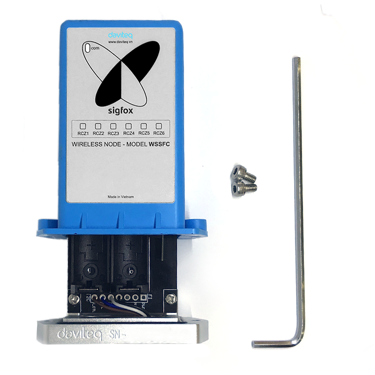
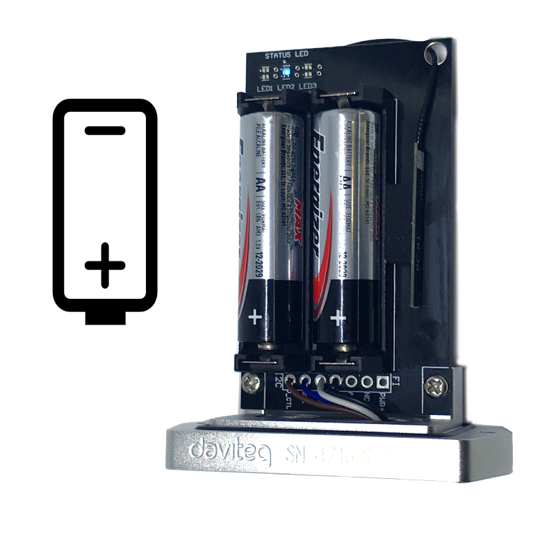
Step 2: Insert 02 x AA 1.5VDC battery, please take note the poles of the battery
ATTENTION:
REVERSED POLARITY OF BATTERIES IN 10 SECONDS CAN DAMAGE THE SENSOR CIRCUIT!!!
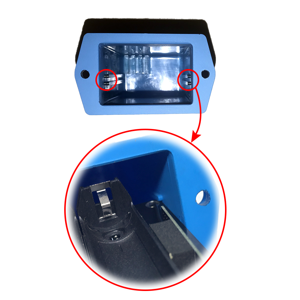
ATTENTION:
When reinstalling the cover, pay attention to put the PCB edge into the middle slot of the box inside as shown below)
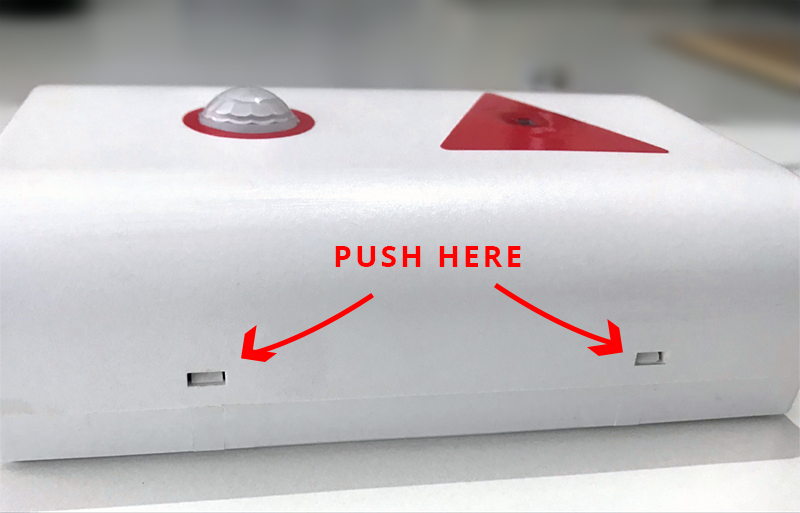
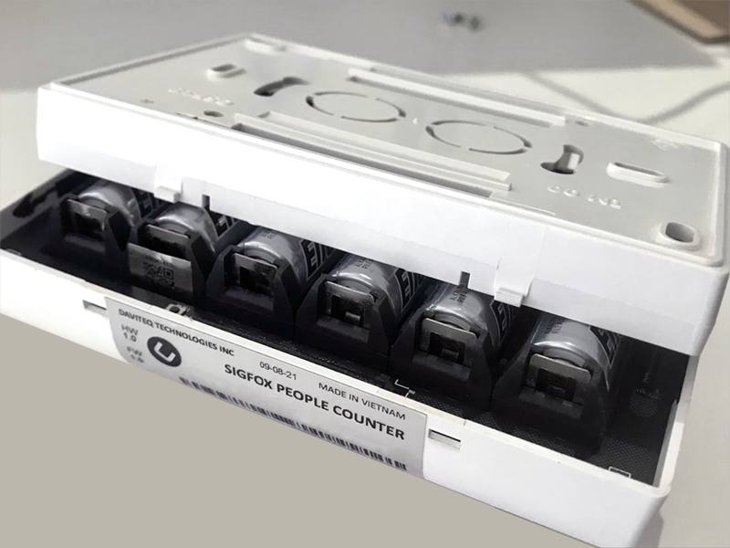
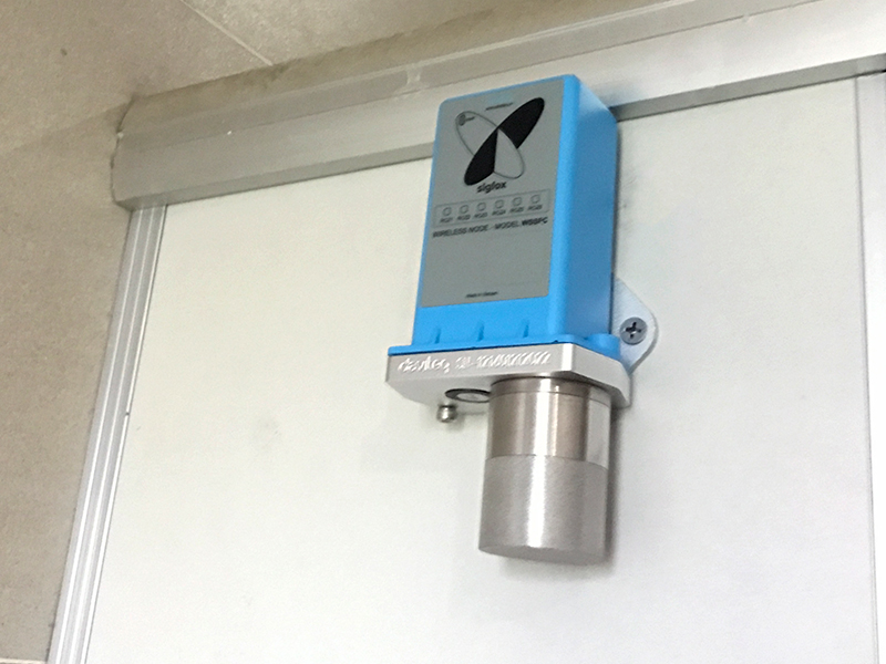
2.2 INSTALL BATTERIES FOR SIGFOX-READY SENSOR WITH WHITE BOX HOUSING, 6 X AA BATTERIES (SENSOR -LPC)

Steps for battery installation:
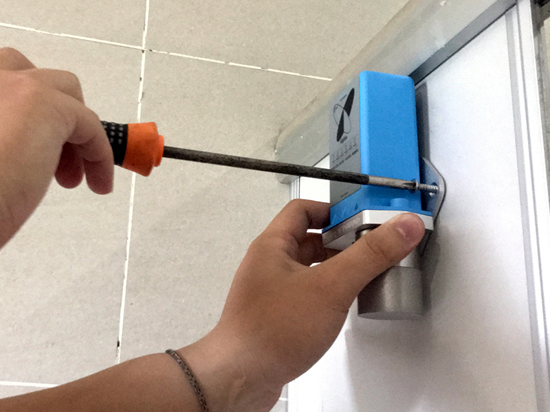
Step 1: Use flat head screws to push into 2 reed joints
Step 2: Open the housing, then insert 06 x AA 1.5VDC battery, please take note of the poles of the battery
ATTENTION: REVERSED POLARITY OF BATTERIES IN 10 SECONDS CAN DAMAGE THE SENSOR CIRCUIT!!!
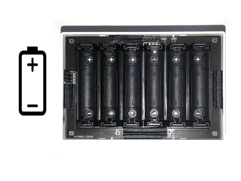
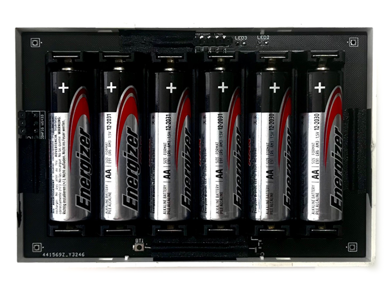
Step 3: Insert the top plastic housing (Please note the 2 reed joints)
2.3 INSTALL BATTERIES FOR SIGFOX-READY SENSOR WITH BLACK BOX HOUSING, 2 X AA BATTERIES (SENSOR -ULA)
Steps for battery installation:
Step 1: Use a screwdriver to open the 4 screws on the underside of the housing
.png)
Step 2: Open the housing, then insert 02 x AA 1.5VDC battery
ATTENTION: REVERSED POLARITY OF BATTERIES IN 10 SECONDS CAN DAMAGE THE SENSOR CIRCUIT!!!
.png)
Step 3: Insert the plastic housing and locking the 4 screws by screwdriver
.png)
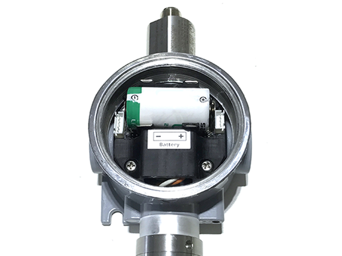
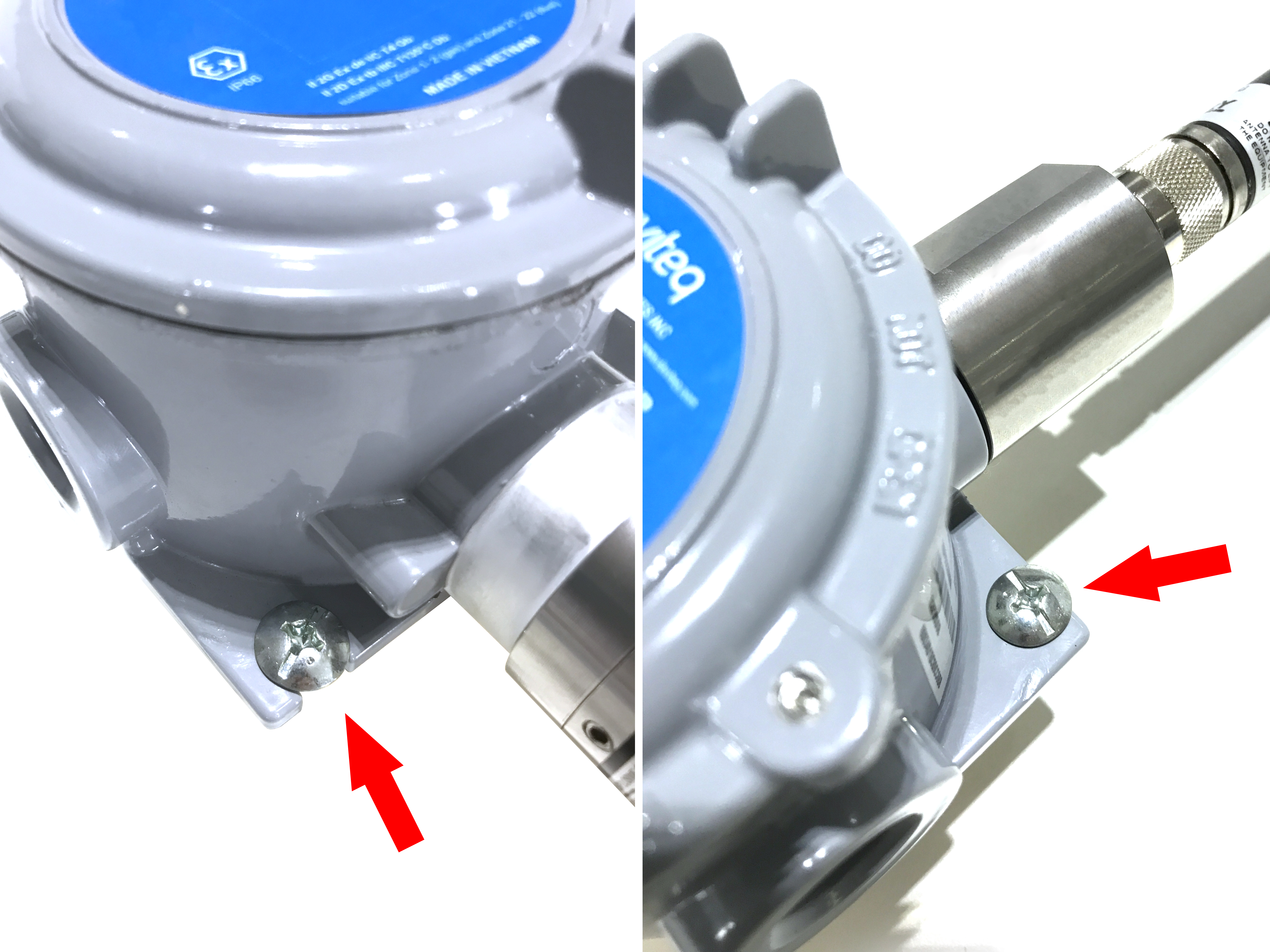
2.4 INSTALL BATTERIES FOR SIGFOX-READY SENSOR WITH EXD-APPROVED HOUSING WSSFCEX-...
Depends on the design of each device. Each device may need 1 pc of Type C or Type D battery. Please check the specification of that device. We recommend the below batteries to be used with our devices.
 |
 |
Steps for battery installation:
DANGER:
DO NOT REPLACE BATTERY AT HAZARDOUS LOCATION!
DO NOT OPEN THE COVER AT HAZARDOUS LOCATION!
ONLY OPEN COVER AND REPLACE BATTERY IN SAFE AREA!
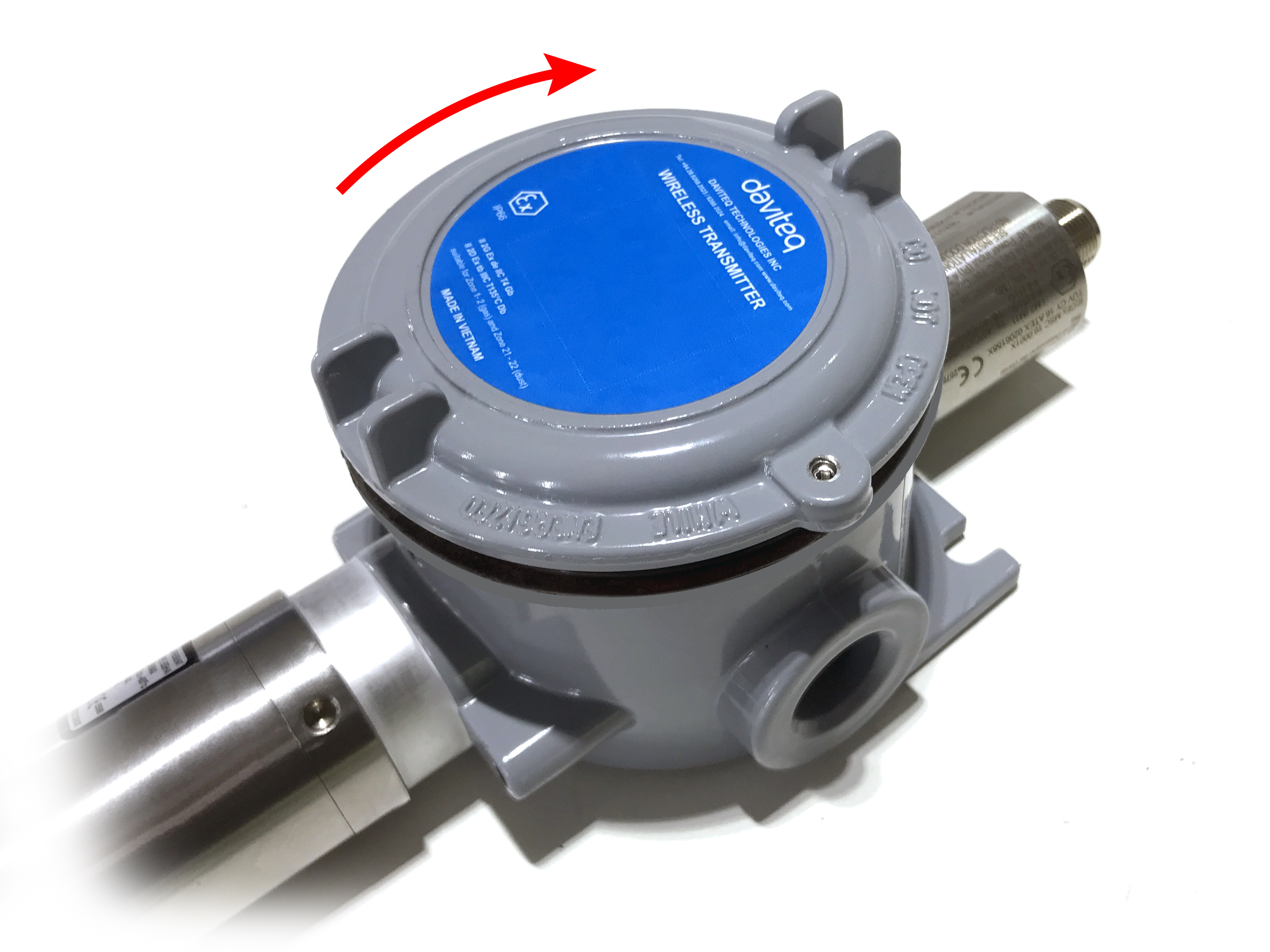
Step 1: Turn the front cover of the sensor counter-clockwise;

Step 2: Carefully take out the front cover of the sensor
Step 3: Insert the battery, please take note the polarity of battery
ATTENTION:
REVERSED POLARITY OF BATTERIES IN 10 SECONDS CAN DAMAGE THE SENSOR CIRCUIT!!!
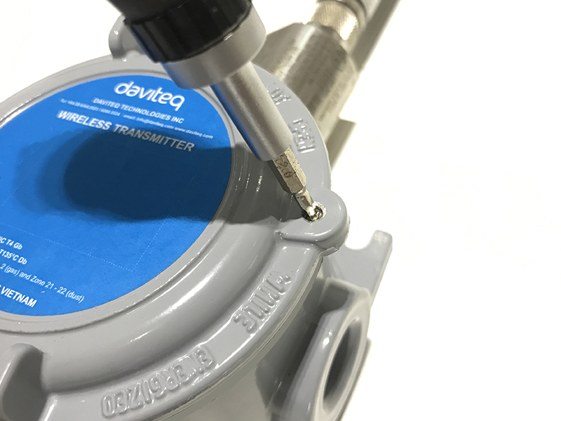
Step 4: Turn the front cover of the sensor clockwise to close fully.
NOTES:
Using 2mm hex key to lock the cover to prevent the unattended opening.
3. MOUNTING FOR SIGFOX-READY SENSOR
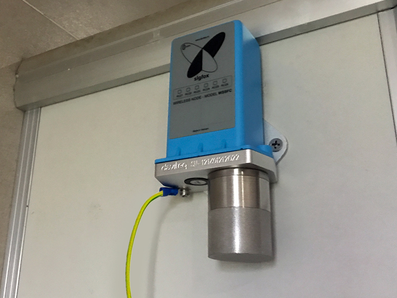
3.1 MOUNTING FOR SIGFOX-READY SENSOR WITH BLUE BOX HOUSING
The following are the steps for the Sigfox-ready sensor with a Blue box housing design.
Step 1: Install the bracket on the sensor

Step 2: Determine the mounting position and secure the sensor with the included screws
Step 3:Grounding the sensor
3.2 MOUNTING FOR SIGFOX-READY SENSOR WITH WHITE BOX HOUSING
3.3 MOUNTING FOR SIGFOX-READY SENSOR WITH EXD-APPROVED HOUSING
4. ADDING A SIGFOX-READY SENSOR TO SIGFOX BACK-END SYSTEM
This instruction is applied to all kinds of Sigfox-Ready sensors produced by Daviteq.
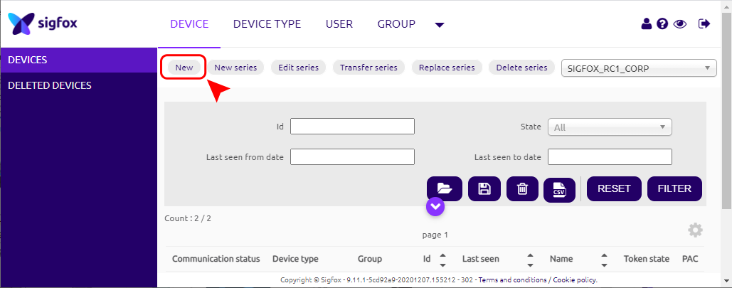
Step 1: Log in to the sigfox backend website

Step 2: Click on Device

Step 3: Click New → Select a group
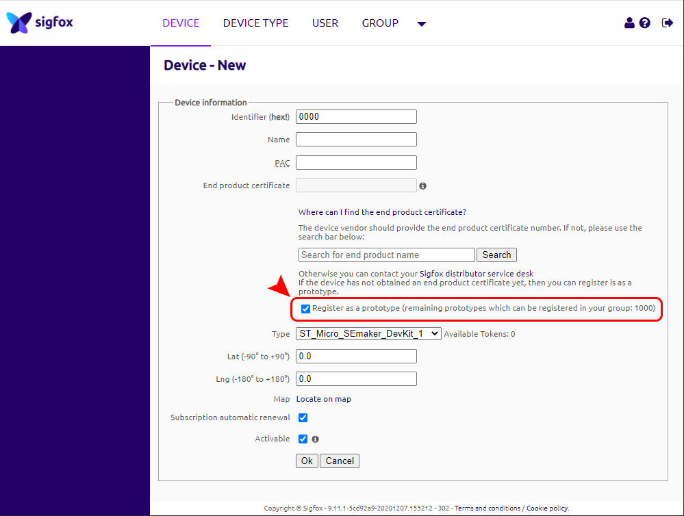
Step 4: Fill in the required information
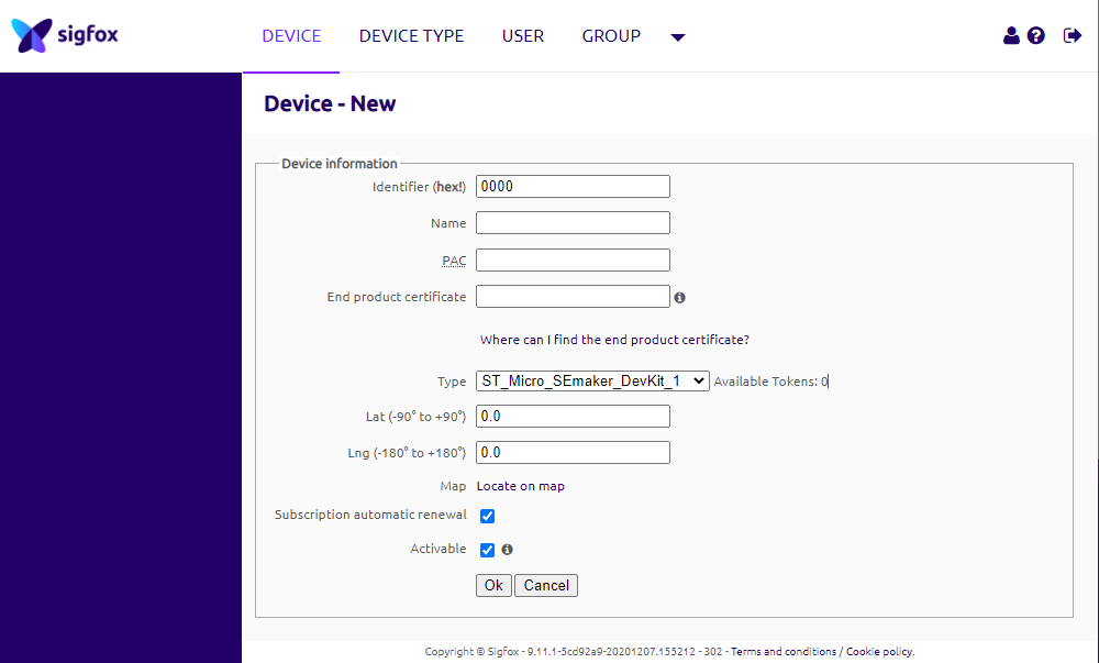
Note: Some of our products may not have end product certification in time, to add the product to Backend Sigfox please follow the steps below.
Click on the text as shown below
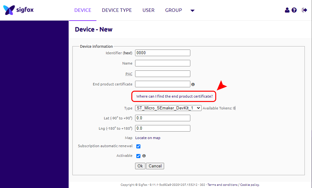
Check the box as shown below to register as a prototype