Manual for Sigfox Sensors - Type 2
Sigfox Sensors - Type 2 are Tilt sensor, Soil moisture, Humidity... the sensor with Blue box housing.
- Manual for Sigfox-Ready AC Current Sensor - WSSFC-AC | FW1
- Manual for Sigfox-Ready Air/Gas Flow Sensor - WSSFC-M12F-AFD | FW1
- Manual for Sigfox-Ready Single-Axis Vibration Sensor - WSSFC-V1A | FW2
- Manual for Sigfox-Ready AC Current Sensor - WSSFC-AC | FW3
- Manual for Sigfox-Ready Single-Axis Vibration Sensor - WSSFC-V1A | FW3
Manual for Sigfox-Ready AC Current Sensor - WSSFC-AC | FW1
THIS IS OBSOLETE MANUAL
Please access https://www.iot.daviteq.com/wireless-sensors for updated manual
Thank you very much for choosing Daviteq Wireless Sensors. We are the leading wireless sensor manufacturer in the World. We have a wide range of wireless sensors which support different connectivity like LoRaWAN, Sigfox, Sub-GHz, NB-IoT...Please find out more information at this link.
This manual is applied to the following products
| Item code | HW Version | Firmware Version | Remarks |
| WSSFC-AC-11 | 1.0 | 1.0 |
Information Changes in this version v.s previous version
| Item | Changes | Changed by | Changed Date | Approved by | Approved Date |
| 1 | Initial version | D.Q.Tuan | 09-04-2022 | N.V.Loc | 28-06-2022 |
To use this product, please refer step by step to the below instructions.
1. Quick Guide
Reading time: 10 minutes
Finish this part so you can understand and put the sensor in operation with the default configuration from the factory.
1.1 What is the Sigfox-Ready AC Current Sensor and its principle of operation?
WSSFC-AC is a Sigfox-Ready sensor with an integrated AC current measuring transducer that can measure the AC current from a current transformer with max 5A AC current. It is compatible with any brand of current transformer (CT) on the market which gives an output max of 5A AC. The CT ratio will be selected based on the load current.
It is battery-operated and able to connect to any Sigfox network in the World. It supports all frequency zones such as RC1, RC2, RC3c, RC4, RC5, RC6, and RC7.
For the principle operation of the AC current sensor, please refer to this link.
1.1.1 What are the typical applications of this sensor?
Please refer to this link for typical applications.
1.1.2 When does the device send uplink messages?
The device will send uplink messages in the following cases:
- Case 1: After power-up in the 60s, the device will send the first message called START_UP. The payload will tell the user the HW version, FW version, and current configuration of the device;
- Case 2: Then, in every interval time (pre-configured), for example, 10 minutes, it will send the message called CYCLIC_DATA. The payload will tell the user the following data like measured value (AC current value), battery level, alarm status...
To change the cycle of data sending, you can change the value of the parameter: CYCLIC_DATA_PERIOD (default is 600 seconds).
- Case 3: In case the Alarm function was enabled (in the configuration of the sensor), if the measured value passed the threshold, it will send the uplink message immediately. This message is called ALARM. The payload also tells the user the data like measured value (AC current value), battery level, alarm status...
The alarm thresholds can be changed via downlink or offline tools.
- Case 4: The HEART_BEAT uplink message will be sent once a day (the default setting, can be changed in configuration) to allow the Sigfox back-end system can send the downlink message for changing the configuration of the sensor. Please refer to the downlink section for more details. The uplink payload will tell the user the HW version, FW version, and current configuration of the device;
- Case 5: During commissioning, testing, or calibration sensor, the user can force the device to send the uplink message so that they can get the data immediately. This message is called FORCE_DATA. The payload will provide data like raw measured value, scaled measured value, battery level, alarm status... It can be forced by applying the magnet key on the reed switch in 1s;
- Case 6: In case users want to change the configuration immediately, they don't need to wait up to 1 day for the HEART_BEAT message, instead they can force the device to send a special uplink message so that the device can get the new downlink message. This uplink message is named PARAMETERS_UPDATE. It can be forced by applying the magnet key in more than 5s.
1.1.3 The important configuration parameters
The sensor was pre-configured at the factory with default values for configuration parameters that meet the most use cases. However, depending on the specific use case, the customer can adjust those parameters. Please refer to section 3.2 for more details.
1.1.4 What kind of battery is used for this sensor?
The sensor is powered by 2 x AA 1.5V batteries for many years of operation. We do recommend using Energizer L91 battery which is very popular and high performance. This battery has a capacity of up to 3500mAh with a working temperature range from -40 to +60 oC. The instruction for installing the batteries is in this link.

For Battery life estimation, please refer to this link.
1.2 What's in the package?
The package includes:
01 x Main device
01 x AC current measuring transducer M12 and cable
01 x Magnet key
01 x Wall mounting bracket and screws
.png)
1.3 Quick Test
With the default configuration, the device can be connected quickly to the Sigfox Network by the following steps.
Step 1: Prepare the values of communication settings:
|
Device ID |
Get Devive ID on the device nameplate |
|
Device PAC |
Get Devive PAC on the device nameplate |
Note: All Sigfox sensors are pre-configured with the correct RC before delivery. The settings of Device ID, Device PAC, and RC could be also read from the device memory map. Please reference section 3.2 Sensor configuration for details.
Step 2: Add the device to Sigfox Backend
Please refer to this link for details
Step 3: Install the batteries to the device
Please refer to this link for instructions on battery installation.
After installing the battery in 60 seconds, the first data packet will be sent to the Sigfox network. After receiving the first data packet, the time of another packet depends on the value of the parameter: CYCLIC_DATA_PERIOD. Additionally, you can use a Magnet Key to force the device to send data instantly.
Step 4: Decode the payload of receiving package
Please refer to section 1.4 Uplink Payload and Data Decoding for details of decoding the receiving packet to get the measured values.
1.4 Uplink Payload and Data Decoding
For the Uplink Payload structure, please refer to this link.
Note: Please select the right Payload document to suit the FW version of the sensor
1.5 Sensor Installation
SAFETY ATTENTION:
- TO REPLACE BATTERIES OR SERVICE THE MAIN DEVICE, PLEASE PAY ATTENTION TO THE ELECTRICAL SHOCK THAT MAY HAPPEN DUE TO THE PROBLEM OF THE AC CURRENT CABLE OR FAILURE OF THE CURRENT TRANSFORMER. FOR SAFETY REASONS, REMOVE THE AC CURRENT TRANSDUCER OUT OF THE MAIN DEVICE BY UN-SCREWING THE M12 CONNECTOR BEFORE OPENING THE PLASTIC HOUSING OF THE MAIN DEVICE;
- ONLY QUALIFIED ELECTRICAL TECHNICIANS CAN HANDLE THIS DEVICE FOR INSTALLATION, MAINTENANCE, AND OPERATION;
- USE THE HEAT-SHRINK PVC TUBE TO PROTECT THE CONNECTIONS ON THE CABLE OF THE AC CURRENT AND AVOID THE WATER CONTACT WITH THOSE ELECTRICAL CONNECTIONS.
DIMENSIONS OF PRODUCT
The Sigfox-Ready AC current sensor is a combination of a wireless transmitter and an AC current transducer. Therefore, the installation will be divided into 02 parts:
- Installation for the wireless transmitter: these steps are to make sure the device sends data successfully;
- Installation for AC current circuit: these steps are to make sure the device to measure correctly.
Please follow the orders of steps strictly as below.
1.5.1 Preparation of the locations
- Locate the place to mount the CT, the place that is to measure the load current;
- Locate the place to mount the Wireless transmitter to get the best RF signal. As the AC current transducer will be attached to the wireless transmitter, please make sure the cable length is enough for the distance from CT to the wireless transmitter;
To get a strong RF signal please refer to this link.
1.5.2 Wireless Transmitter Installation
- Mount the wireless transmitter on the wall or outside the wall of the electrical panel. The antenna part must be higher than the highest point of the electrical panel. Then connect the grounding wire from the base of the wireless transmitter (if available) to the grounding system of the facility. Please check this link for the mounting guide;
- Insert the batteries into the wireless transmitter and check the system to see whether the wireless transmitter already sent the first message to the system? Please follow this link to know how to install the batteries.
ATTENTION:
REVERSED POLARITY OF BATTERIES IN 10 SECONDS CAN DAMAGE THE SENSOR CIRCUIT!!!
1.5.3 CT Installation
- Shut down the main load before installing the CT
- For closed-type CT, please shut down the main load before installing the CT.
- For clamp-type CT, it is possible to install the CT onto the load wire, however, we highly recommend shutting down the main load for safety reasons.
- Danger: be aware of electrical shock with AC voltage!
1.5.4 Connect the CT with the AC current transducer
Use the crimping tool to make the connection and protect the connection with a PVC heat shrink tube as this link.
1.5.5 Connect the AC transducer to Wireless Transmitter
Connect the AC transducer to the wireless transmitter via the M12 connector as this link.
1.5.6 Device calibration
The Sigfox-Ready AC current transducer is produced with accuracy as published in the specification of the product and is ready to use. However, the user can re-calibrate the sensor again when necessary, please follow the steps in this link.
1.5.7 Turn on the Main load again
After connecting, the sensor will send the data to the system with the value = zero (no AC current). Then you can turn ON the main load again to put the system into the operation.
You can use a clamp-type ampere meter to validate the value reading from the system. Please make sure the two comparison values must be collected at the same time.
2. Maintenance
2.1 Troubleshooting
- Problems with Sigfox communication like not receiving the packets...please refer to this link to troubleshoot the device.
- Problems with the sensor functions like not measuring, or inaccurate measuring....please refer to this link to troubleshoot the sensor part.
2.2 Sensor maintenance
| Maintenance works | Yes/No |
Descriptions |
| Consumable parts replacement | No |
The Sigfox-Ready AC current sensor has no consumable part, so there is no need to replace any parts. |
| Cleaning sensor or device | No |
|
| Re-calibration / Re-validation | Yes | The transducer may need to be re-calibrated when necessary. Please refer to this link for the procedure of calibration. |
3. Advanced Guide
3.1 Operating principle of the Sigfox-Ready AC current sensor
3.1.1 Operating principle of the complete device
The Daviteq Sigfox-Ready AC current sensor comprises 02 parts connected together as shown below picture.
- The Daviteq Sigfox-Ready wireless transmitter;
- The Daviteq AC 5A current Transducer;
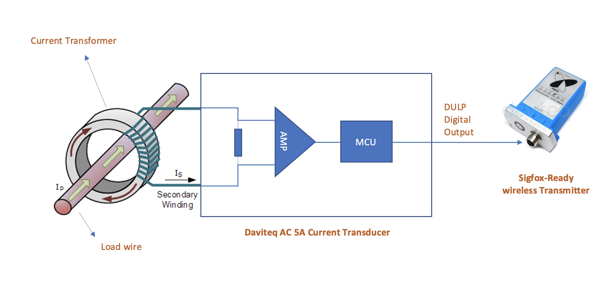
The AC current transducer is to measure the actual AC current of the secondary winding of the CT.
The Sigfox-Ready is to read the AC current value from the transducer and perform the scaling (A and B values, during calibration). The scaled current will be multiplied by the CT ratio to deliver the final value which is the actual load current that the user wants to measure.
Scaled_CT_Current = A x CT_Current + B
Actual_Load_Current = Scaled_CT_Current x CT
Where:
A : Constant A
B : Constant B
CT_current: the measured current from the transducer (Secondary winding current of the CT)
For example: the CT_current = 1.5A, the CT ratio = 20 (the CT is 100/5), A=1, B=0 ==> then the Actual_Load_Current = 1.5 x 20 = 30A
Note: the Low cut value of Actual_Load_Current is 0.5A. That meant the device can not measure the current load less than 0.5A
3.1.2 Operating principle of AC current transducer
To understand how the AC current transducer can measure AC current, please refer to this link for a complete understanding of this measuring technique.
3.1.3 Some important configuration parameters
Below are some important configuration parameters which affect the operation of the device like battery life, measurement accuracy, and alert threshold.
For Battery life estimation, please refer to this link.
- measure_period | Default = 600s
This is the time period for the wireless transmitter to wake up and take the measurement from the transducer. The default value is 600s. Users can reduce this value, but smaller value, shorter battery life! - cyclic_data_period | Default = 600s
Interval time to send an uplink message regardless of any conditions - sensor_boot_time | Default = 1000mS
This value will affect the measurement accuracy. DO NOT change this value!
Those configuration parameters can be changed by downlink or offline tools. For more other configuration parameters, please refer to the next section.
3.2 Sensor Configuration
3.2.1 How to configure the Sigfox-Ready AC Current Sensor?
Sensor configuration can be configured in 02 methods:
- Method 1: Configuring via Downlink message. Please find the instructions in this link, but please take note of the FW version of the Document.
- Method 2: Configuring via offline cable.
Note: THE SENSOR IS ONLY ACTIVE FOR OFFLINE CONFIGURATION IN THE FIRST 60 SINCE POWER UP BY BATTERY OR PLUGGING THE CONFIGURATION CABLE.
3.2.2 What parameters of the device are configured?
- Some parameters are read-only, and some are read and writeable.
- To read the parameters, use the off-line cable as above instruction.
- Via uplink message, users can read only one parameter, which is the CURRENT_CONFIGURATION.
Below tables are the lists of the parameters of the device.
Read-only Parameter Table
|
Modbus Register (Decimal) |
Modbus Register (Hex) |
Function Code (Read) |
No. of Registers |
Description |
Range |
Format |
Property |
Comment |
|
2 |
2 |
3 |
4 |
FW_VERSION |
|
string |
Read |
|
|
6 |
6 |
3 |
2 |
HW_VERSION |
|
string |
Read |
|
|
8 |
8 |
3 |
2 |
DEVICE_ID |
|
hex |
Read |
Product ID |
|
10 |
A |
3 |
4 |
DEVICE_PAC |
|
hex |
Read |
Product PAC |
|
14 |
E |
3 |
1 |
SENSOR_TYPE |
1-255 |
uint16 |
Read |
Sensor or Input Type |
Read/Write Parameter Table
|
Modbus Register (Decimal) |
Modbus Register (Hex) |
Function Code (Read) |
Function Code (Write) |
No. of Registers |
Description |
Range |
Default |
Format |
Property |
Comment |
|
270 |
10E |
3 |
16 |
4 |
CURRENT_CONFIGURATION |
|
|
hex |
Read/Write |
Check the Payload Document section: 5.Payload for downlink message for more information |
|
274 |
112 |
3 |
16 |
1 |
SERVER_CONFIG |
|
|
uint16 |
Read/Write |
0: Send to Sigfox Network 1: Send to Dongle |
|
276 |
114 |
3 |
16 |
1 |
RADIO_CONFIG |
1-4 |
4 |
uint16 |
Read/Write |
RC zones selection 1, 2 , 3, 4 is RC1, RC2, RC3s, RC4 |
|
277 |
115 |
3 |
16 |
1 |
TX_POWER |
|
20 |
int16 |
Read/Write |
RF Tx power |
|
278 |
116 |
3 |
16 |
2 |
CONSTANT_A |
|
1 |
float |
Read/Write |
Constant a for scaling measured value |
|
280 |
118 |
3 |
16 |
2 |
CONSTANT_B |
|
0 |
float |
Read/Write |
Constant b for scaling measured value |
|
282 |
11A |
3 |
16 |
2 |
HIGH_CUT |
|
1E+09 |
float |
Read/Write |
High cut value for the calculated value |
|
284 |
11C |
3 |
16 |
2 |
LOW_CUT |
|
0,5 |
float |
Read/Write |
Low cut value for the calculated value |
|
286 |
11E |
3 |
16 |
2 |
SENSOR_BOOT_TIME |
|
1000 |
uint32 |
Read/Write |
Boot time of sensor/input, in ms |
|
306 |
132 |
3 |
16 |
2 |
CT |
|
40 |
float |
Read/Write |
CT of current transformer |
3.3 Calibration for Sigfox-Ready AC current transducer
Please refer to this link.
4. Product specification
Please refer to the detailed specifications in this link.
5. Warranty and Support
For warranty terms and support procedures, please refer to this link.
6. References
Use-cases:
Case studies:
White-papers:
END.
Manual for Sigfox-Ready Air/Gas Flow Sensor - WSSFC-M12F-AFD | FW1
THIS IS OBSOLETE MANUAL
Please access https://www.iot.daviteq.com/wireless-sensors for updated manual
Thank you very much for choosing Daviteq Wireless Sensors. We are the leading wireless sensor manufacturer in the World. We have a wide range of wireless sensors which support different connectivity like LoRaWAN, Sigfox, Sub-GHz, NB-IoT...Please find out more information at this link.
This manual is applied to the following products
| Item code | HW Version | Firmware Version | Remarks |
| WSSFC-M12F-AFD | 1 |
Product Features
| Connectivity Type | Sigfox |
| Product Type | 2 parts |
| Mounting Type | Direct process mounting for the whole set |
| Powered by | 2 x AA batteries 1.5V |
Information Changes in this version v.s previous version
| Item | Changes | Changed by | Changed Date | Approved by | Approved Date |
| 1 | Initial version | D.Q.Tuan | 26-08-2022 | N.V.Loc | 05-09-2022 |
To use this product, please refer step by step to the below instructions.
1. Quick Guide
Reading time: 10 minutes
Finish this part so you can understand and put the sensor in operation with the default configuration from the factory.
1.1 What is the Sigfox-Ready AFD Air/Gas Flow Sensor and its principle of operation?
WSSFC-M12F-AFD is a Sigfox-Ready node to work with an AFD probe for measuring the Air/Gas Flow in a pipe or duct.
It is battery-operated and able to connect to any Sigfox network in the World. It supports all frequency zones such as RC1, RC2, RC3c, RC4, RC5, RC6, and RC7.
For the principle operation of the AFD probe, please refer to this link.
1.1.1 What are the typical applications of this sensor?
Please refer to this link for typical applications.
1.1.2 When does the device send uplink messages?
The device will send uplink messages in the following cases:
- Case 1: After power-up in the 60s, the device will send the first message called START_UP. The payload will tell the user the HW version, FW version, and current configuration of the device;
- Case 2: Then, in every interval time (pre-configured), for example, 10 minutes, it will send the message called CYCLIC_DATA. The payload will tell the user the following data like measured value (AC current value), battery level, alarm status...
To change the cycle of data sending, you can change the value of the parameter: CYCLIC_DATA_PERIOD (default is 600 seconds).
- Case 3: If the Alarm function was enabled (in the configuration of the sensor), if the measured value passed the threshold, it will send the uplink message immediately. This message is called ALARM. The payload also tells the user the data like measured value (AC current value), battery level, alarm status...
The alarm thresholds can be changed via downlink or offline tools.
- Case 4: The HEART_BEAT uplink message will be sent once a day (the default setting can be changed in configuration) to allow the Sigfox back-end system can send the downlink message for changing the configuration of the sensor. Please refer to the downlink section for more details. The uplink payload will tell the user the HW version, FW version, and current configuration of the device;
- Case 5: During commissioning, testing, or calibration sensor, the user can force the device to send the uplink message to get the data immediately. This message is called FORCE_DATA. The payload will provide data like raw measured value, scaled measured value, battery level, alarm status... It can be forced by applying the magnet key on the reed switch in 1s;
- Case 6: If users want to change the configuration immediately, they don't need to wait up to 1 day for the HEART_BEAT message, instead they can force the device to send a special uplink message so that the device can get the new downlink message. This uplink message is named PARAMETERS_UPDATE. It can be forced by applying the magnet key in more than 5s.
1.1.3 The important configuration parameters
The sensor was pre-configured at the factory with default values for configuration parameters that meet most use cases. However, depending on the specific use case, the customer can adjust those parameters. Please refer to section 3.2 for more details.
1.1.4 What kind of battery is used for this sensor?
The sensor is powered by 2 x AA 1.5V batteries for many years of operation. We do recommend using Energizer L91 battery which is very popular and high performance. This battery has a capacity of up to 3500mAh with a working temperature range from -40 to +60 oC. The instruction for installing the batteries is in this link.
Figure 1. Battery Energizer L91
For Battery life estimation, please refer to this link.
1.2 What's in the package?
The package includes:
01 x Main device
01 x Magnet key
01 x Wall mounting bracket and screws
01 x AFD flow sensor probe (order separately with item code AFD-....)
.png)
Figure 2. Product package of WSSFC-M12F-AFD
.png)
Figure 3. Product package of AFD-....
1.3 Quick Test
With the default configuration, the device can be connected quickly to the Sigfox Network by the following steps.
Step 1: Prepare the values of communication settings:
|
Device ID |
Get Devive ID on the device nameplate |
|
Device PAC |
Get Devive PAC on the device nameplate |
Note: All Sigfox sensors are pre-configured with the correct RC before delivery. The settings of Device ID, Device PAC, and RC could also be read from the device memory map. Please reference section 3.2 Sensor configuration for details.
Step 2: Add the device to Sigfox Backend
Please refer to this link for details
Step 3: Install the batteries to the device
Please refer to this link for instructions on battery installation.
After installing the battery in 60 seconds, the first data packet will be sent to the Sigfox network. After receiving the first data packet, the time of another packet depends on the value of the parameter: CYCLIC_DATA_PERIOD. Additionally, you can use a Magnet Key to force the device to send data instantly.
Step 4: Decode the payload of receiving package
Please refer to section 1.4 Uplink Payload and Data Decoding for details of decoding the receiving packet to get the measured values.
1.4 Uplink Payload and Data Decoding
For the Uplink Payload structure, please refer to this link.
Note: Please select the right Payload document to suit the FW version of the sensor
1.5 Sensor Installation
DIMENSIONS OF PRODUCT
.png)
Figure 4. Dimensions of WSSFC-M12F-AFD
.png)
Figure 5. Dimensions of AFD-0200
1.5.1 Installation
The Sigfox-Ready AFD Air/Gas flow sensor combines a wireless transmitter WSSFC-M12F-AFD and an AFD Air/Gas Flow Sensor. Therefore, the installation will be divided into 02 parts:
+ Installation for AFD Air/Gas Flow Sensor: these steps are to make sure the device to measure correctly. Please follow this link.
+ Installation for the wireless transmitter: these steps ensure the device sends data successfully. Please see below the steps
-
- Insert the batteries into the wireless transmitter and check the system to see whether the wireless transmitter already sent the first message to the system. Please follow this link to learn how to install the batteries.
ATTENTION:
REVERSED POLARITY OF BATTERIES IN 10 SECONDS CAN DAMAGE THE SENSOR CIRCUIT!!!
- Insert the batteries into the wireless transmitter and check the system to see whether the wireless transmitter already sent the first message to the system. Please follow this link to learn how to install the batteries.
-
- Attach the wireless transmitter to the AFD probe as below figures.
.png)
Figure 6. Complete set of WSSFC-M12F-AFD and AFD-0200
1.5.2 Device calibration & configuration
Please refer to this link.
2. Maintenance
2.1 Troubleshooting
- Problems with Sigfox communication like not receiving the packets...please refer to this link to troubleshoot the device.
- Problems with the sensor functions like not measuring or inaccurate measuring....please refer to this link to troubleshoot the sensor part.
2.2 Device maintenance
2.2.1 Maintenance for Wireless transmitter WSSFC-M12F-AFD
| Maintenance works | Yes/No |
Descriptions |
| Consumable parts replacement | Yes |
The battery is the only part need to check the lifetime to replace. Check the battery status on the back-end system. |
| Cleaning device | No |
|
| Re-calibration / Re-validation | No | No calibration is required for the wireless transmitter. |
2.2.2 Maintenance for AFD flow probe
Please refer to this link.
3. Advanced Guide
3.1 Operating principle of the Sigfox-Ready AFD Air/Gas Flow Sensor
3.1.1 Operating principle of the complete device
The Daviteq Sigfox-Ready AFD Air/Gas Flow sensor comprises 02 parts connected together as shown below picture.
- The Daviteq Sigfox-Ready wireless transmitter WSSFC-M12F-AFD
- The Daviteq AFD Air/Gas Flow Sensor AFD-...
Figure 7. Complete set of WSSFC-M12F-AFD and AFD-0200
The AFD Air/Gas Flow Sensor measures pressure and temperature... in the duct or pipe.
The Sigfox-Ready wireless transmitter is to read the parameters of the probe like differential pressure, temperature, and error code... and performs the scaling and calculation to deliver the fluid velocity in the duct or pipe.
3.1.2 Operating principle of AFD Air/Gas Flow Sensor
To understand how the AFD Air/Gas Flow Sensor works, please refer to this link for a complete understanding of this measuring technique.
3.1.3 Some important configuration parameters
Below are some important configuration parameters which affect the operation of the device like battery life, measurement accuracy, and alert threshold.
For Battery life estimation, please refer to this link.
- measure_period | Default = 600s
This is the time period for the wireless transmitter to wake up and take the measurement from the transducer. The default value is 600s. Users can reduce this value, but smaller value, shorter battery life! - cyclic_data_period | Default = 1800s
Interval time to send an uplink message regardless of any conditions - sensor_boot_time | Default = 200mS
This value will affect the measurement accuracy. DO NOT change this value!
- density_of_fluid | Default = 1.225 (Air)
This value will affect the measurement accuracy.
Those configuration parameters can be changed by downlink or offline tools. For more other configuration parameters, please refer to the next section.
3.2 Sensor Configuration
3.2.1 How to configure the Sigfox-Ready AFD Air/Gas Flow Sensor?
Sensor configuration can be configured in 02 methods:
- Method 1: Configuring via Downlink message. Please find the instructions in this link, but please take note of the FW version of the Document.
- Method 2: Configuring via offline cable.
Note: THE SENSOR IS ONLY ACTIVE FOR OFFLINE CONFIGURATION IN THE FIRST 60 SINCE POWER UP BY BATTERY OR PLUGGING THE CONFIGURATION CABLE.
3.2.2 What parameters of the device are configured?
- Some parameters are read-only, and some are read and writeable.
- To read the parameters, use the off-line cable as above instruction.
- Via uplink message, users can read only one parameter, which is the CURRENT_CONFIGURATION.
Below tables are the lists of the parameters of the device.
Read-only Parameter Table
|
Modbus Register (Decimal) |
Modbus Register (Hex) |
Function Code (Read) |
No. of Registers |
Description |
Range |
Format |
Property |
Comment |
|
2 |
2 |
3 |
4 |
FW_VERSION |
|
string |
Read |
|
|
6 |
6 |
3 |
2 |
HW_VERSION |
|
string |
Read |
|
|
8 |
8 |
3 |
2 |
DEVICE_ID |
|
hex |
Read |
Product ID |
|
10 |
A |
3 |
4 |
DEVICE_PAC |
|
hex |
Read |
Product PAC |
|
14 |
E |
3 |
1 |
SENSOR_TYPE |
1-255 |
uint16 |
Read |
Sensor or Input Type |
Read/Write Parameter Table
|
Modbus Register (Decimal) |
Modbus Register (Hex) |
Function Code (Read) |
Function Code (Write) |
No. of Registers |
Description |
Range |
Default |
Format |
Property |
Comment |
|
270 |
10E |
3 |
16 |
4 |
CURRENT_CONFIGURATION |
|
|
hex |
Read/Write |
Check the Payload Document section: 5.Payload for downlink message for more information |
|
274 |
112 |
3 |
16 |
1 |
SERVER_CONFIG |
|
0 |
uint16 |
Read/Write |
0: Send to Sigfox Network 1: Send to Dongle |
|
276 |
114 |
3 |
16 |
1 |
RADIO_CONFIG |
1-4 |
4 |
uint16 |
Read/Write |
RC zones selection 1, 2 , 3, 4 is RC1, RC2, RC3s, RC4 |
|
277 |
115 |
3 |
16 |
1 |
TX_POWER |
|
20 |
int16 |
Read/Write |
RF Tx power |
|
278 |
116 |
3 |
16 |
2 |
CONSTANT_A |
|
1 |
float |
Read/Write |
Constant a for scaling measured value |
|
280 |
118 |
3 |
16 |
2 |
CONSTANT_B |
|
0 |
float |
Read/Write |
Constant b for scaling measured value |
|
282 |
11A |
3 |
16 |
2 |
HIGH_CUT |
|
1E+09 |
float |
Read/Write |
High cut value for the calculated value |
|
284 |
11C |
3 |
16 |
2 |
LOW_CUT |
|
0 |
float |
Read/Write |
Low cut value for the calculated value |
|
286 |
11E |
3 |
16 |
2 |
SENSOR_BOOT_TIME |
|
200 |
uint32 |
Read/Write |
Boot time of sensor/input, in ms |
|
307 |
133 |
3 |
16 |
1 |
TEMPERATURE_OFFSET_X10 |
|
0 |
int16 |
Read/Write |
Offset adjustment for measured temperature value |
|
308 |
134 |
3 |
16 |
2 |
DENSITY_OF_FLUID |
|
1.225 |
float |
Read/Write |
Fluid Density, default is Air |
3.3 Calibration for Sigfox-Ready AFD Air/Gas Flow Sensor
Please refer to this link.
4. Product specification
Please refer to the detailed specifications in this link.
5. Warranty and Support
For warranty terms and support procedures, please refer to this link.
6. References
Use-cases:
Case studies:
White-papers:
END.
Manual for Sigfox-Ready Single-Axis Vibration Sensor - WSSFC-V1A | FW2
THIS IS OBSOLETE MANUAL
Please access https://www.iot.daviteq.com/wireless-sensors for updated manual
Thank you very much for choosing Daviteq Wireless Sensors. We are the leading wireless sensor manufacturer in the World. We have a wide range of wireless sensors which support different connectivity like LoRaWAN, Sigfox, Sub-GHz, NB-IoT...Please find out more information at this link.
This manual is applied to the following products
| Item code | HW Version | Firmware Version | Remarks |
| WSSFC-V1A-025 | 2 |
Product Features
| Connectivity Type | Sigfox |
| Product Type | 2 parts |
| Mounting Type | Direct process mounting for sensor, wall mount for transmitter |
| Powered by | 2 x AA batteries 1.5V |
Information Changes in this version v.s previous version
| Item | Changes | Changed by | Changed Date | Approved by | Approved Date |
| 1 | Initial version | D.Q.Tuan | 29-08-2022 | N.V.Loc | 05-09-2022 |
To use this product, please refer step by step to the below instructions.
1. Quick Guide
Reading time: 10 minutes
Finish this part so you can understand and put the sensor in operation with the default configuration from the factory.
1.1 What is the Sigfox-Ready V1A Single-Axis Vibration Sensor and its principle of operation?
WSSFC-V1A is a cost-effective, single-axis vibration sensor designed for condition monitoring and preventive maintenance applications. The piezo-electric accelerometer is available in ranges ±25g or 50g and features a flat frequency response up to >10kHz. Its accelerometer feature a stable piezo-ceramic crystal in shear mode with low-power electronics, sealed in a fully hermetic package. The Piezo Electric technology incorporated in the WSSCF-V1A accelerometer has a proven track record for offering the reliable and long-term stable output required for condition monitoring applications. The accelerometer is designed and qualified for machine health monitoring and has superior Resolution, Dynamic Range, and Bandwidth to MEMS devices. Besides that, it can also measure the temperature at the mounting point.
It is battery-operated and able to connect to any Sigfox network in the World. It supports all frequency zones such as RC1, RC2, RC3c, RC4, RC5, RC6, and RC7.
For the principle operation of the V1A single-axis vibration sensor, please refer to this link.
1.1.1 What are the typical applications of this sensor?
Please refer to this link for typical applications.
1.1.2 When does the device send uplink messages?
The device will send uplink messages in the following cases:
- Case 1: After power-up in the 60s, the device will send the first message called START_UP. The payload will tell the user the HW version, FW version, and current configuration of the device;
- Case 2: Then, in every interval time (pre-configured), for example, 10 minutes, it will send the message called CYCLIC_DATA. The payload will tell the user the following data like measured values, battery level, alarm status...
To change the cycle of data sending, you can change the value of the parameter: CYCLIC_DATA_PERIOD (default is 600 seconds).
- Case 3: If the Alarm function was enabled (in the configuration of the sensor), if the measured value passed the threshold, it will send the uplink message immediately. This message is called ALARM. The payload also tells the user the data like measured values, battery level, alarm status...
The alarm thresholds can be changed via downlink or offline tools.
- Case 4: The HEART_BEAT uplink message will be sent once a day (the default setting can be changed in configuration) to allow the Sigfox back-end system can send the downlink message for changing the configuration of the sensor. Please refer to the downlink section for more details. The uplink payload will tell the user the HW version, FW version, and current configuration of the device;
- Case 5: During commissioning, testing, or calibration sensor, the user can force the device to send the uplink message to get the data immediately. This message is called FORCE_DATA. The payload will provide data like raw measured value, scaled measured value, battery level, alarm status... It can be forced by applying the magnet key on the reed switch in 1s;
- Case 6: If users want to change the configuration immediately, they don't need to wait up to 1 day for the HEART_BEAT message, instead they can force the device to send a special uplink message so that the device can get the new downlink message. This uplink message is named PARAMETERS_UPDATE. It can be forced by applying the magnet key in more than 5s.
1.1.3 The important configuration parameters
The sensor was pre-configured at the factory with default values for configuration parameters that meet most use cases. However, depending on the specific use case, the customer can adjust those parameters. Please refer to section 3.2 for more details.
1.1.4 What kind of battery is used for this sensor?
The sensor is powered by 2 x AA 1.5V batteries for many years of operation. We do recommend using Energizer L91 battery which is very popular and high performance. This battery has a capacity of up to 3500mAh with a working temperature range from -40 to +60 oC. The instruction for installing the batteries is in this link.
Figure 1. Battery Energizer L91
For Battery life estimation, please refer to this link.
1.2 What's in the package?
The package includes:
01 x Main device with 2m M12 cable
01 x Magnet key
01 x Wall mounting bracket and screws
01 x Vibration sensor module V1A
.png)
Figure 2. Product package of WSSFC-V1A-025
1.3 Quick Test
With the default configuration, the device can be connected quickly to the Sigfox Network by the following steps.
Step 1: Prepare the values of communication settings:
|
Device ID |
Get Devive ID on the device nameplate |
|
Device PAC |
Get Devive PAC on the device nameplate |
Note: All Sigfox sensors are pre-configured with the correct RC before delivery. The settings of Device ID, Device PAC, and RC could also be read from the device memory map. Please reference section 3.2 Sensor configuration for details.
Step 2: Add the device to Sigfox Backend
Please refer to this link for details
Step 3: Install the batteries to the device
Please refer to this link for instructions on battery installation.
After installing the battery in 60 seconds, the first data packet will be sent to the Sigfox network. After receiving the first data packet, the time of another packet depends on the value of the parameter: CYCLIC_DATA_PERIOD. Additionally, you can use a Magnet Key to force the device to send data instantly.
Step 4: Decode the payload of receiving package
Please refer to section 1.4 Uplink Payload and Data Decoding for details of decoding the receiving packet to get the measured values.
1.4 Uplink Payload and Data Decoding
For the Uplink Payload structure, please refer to this link.
Note: Please select the right Payload document to suit the FW version of the sensor
1.5 Sensor Installation
1.5.1 Dimension drawings
|
Figure 3. Dimensions of Sigfox Transmitter |
Figure 4. Dimensions of V1A vibration sensor module |
.png)
1.5.2 Installation
The Sigfox-Ready V1A vibration sensor combines a wireless transmitter WSSFC and a V1A vibration sensor. Therefore, the installation will be divided into 02 parts:
| INSTALLATION GUIDE FOR V1A SENSOR MODULE |
INSTALLATION GUIDE FOR WIRELESS TRANSMITTER. PLEASE SEE THE BELOW STEPS. |
- Mount the wireless transmitter on the wall or a pole nearby the object to monitor the vibration. The wireless transmitter must be mounted at the minimum level of 2m from the ground for a better RF signal. To get the strongest RF signal, please follow this link.
- How to mount it with a mounting bracket? please check this guide.
- Insert the batteries into the wireless transmitter and check the system to see whether the wireless transmitter already sent the first message to the system. Please follow this link to learn how to install the batteries.
ATTENTION:
REVERSED POLARITY OF BATTERIES IN 10 SECONDS CAN DAMAGE THE SENSOR CIRCUIT!!!
- Connect the M12 cable to the V1A sensor module as below figure.
.png)
Figure 5. Complete set of WSSFC-V1A-025 vibration sensor
1.5.3 Device calibration & configuration
Please refer to this link.
2. Maintenance
2.1 Troubleshooting
- Problems with Sigfox communication like not receiving the packets...please refer to this link to troubleshoot the device.
- Problems with the sensor functions like not measuring or inaccurate measuring....please refer to this link to troubleshoot the sensor part.
2.2 Device maintenance
2.2.1 Maintenance for Wireless transmitter
| Maintenance works | Yes/No |
Descriptions |
| Consumable parts replacement | Yes |
The battery is the only part need to check the lifetime to replace. Check the battery status on the back-end system. |
| Cleaning device | No |
|
| Re-calibration / Re-validation | No | No calibration is required for the wireless transmitter. |
2.2.2 Maintenance for V1A sensor module
Please refer to this link.
3. Advanced Guide
3.1 Operating principle of the Sigfox-Ready V1A Single-axis Vibration Sensor
3.1.1 Operating principle of the complete device
The Daviteq Sigfox-Ready V1A Single-axis Vibration Sensor comprises 02 parts connected together as shown below picture.
- The Daviteq Sigfox-Ready wireless transmitter
- The Daviteq V1A vibration sensor module
Figure 6. Complete set of WSSFC-V1A-025 vibration sensor mounted on the motor
The V1A single-axis vibration sensor measures the vibration of the object.
The Sigfox-Ready wireless transmitter is to read the measurement values from the V1A sensor and performs the scaling and calculation to deliver accurate outputs.
3.1.2 Operating principle of V1A single-axis vibration sensor
To understand how the V1A single-axis vibration sensor works, please refer to this link for a complete understanding of this measuring technique.
3.1.3 Some important configuration parameters
Below are some important configuration parameters which affect the operation of the device like battery life, measurement accuracy, and alert threshold.
For Battery life estimation, please refer to this link.
- measure_period | Default = 3600s
This is the time period for the wireless transmitter to wake up and take the measurement from the transducer. The default value is 3600s. Users can reduce this value, but smaller value, shorter battery life! - cyclic_data_period | Default = 3600s
Interval time to send an uplink message regardless of any conditions - constant_A | Default = calibrated value by factory
This value will affect the measurement accuracy. DO NOT change this value!
Those configuration parameters can be changed by downlink or offline tools. For more other configuration parameters, please refer to the next section.
3.2 Sensor Configuration
3.2.1 How to configure the Sigfox-Ready V1A Sing-axis Vibration Sensor?
Sensor configuration can be configured in 02 methods:
- Method 1: Configuring via Downlink message. Please find the instructions in this link, but please take note of the FW version of the Document.
- Method 2: Configuring via offline cable.
Note: THE SENSOR IS ONLY ACTIVE FOR OFFLINE CONFIGURATION IN THE FIRST 60 SINCE POWER UP BY BATTERY OR PLUGGING THE CONFIGURATION CABLE.
3.2.2 What parameters of the device are configured?
- Some parameters are read-only, and some are read and writeable.
- To read the parameters, use the off-line cable as above instruction.
- Via uplink message, users can read only one parameter, which is the CURRENT_CONFIGURATION.
Below tables are the lists of the parameters of the device.
Read-only Parameter Table
|
Modbus Register (Decimal) |
Modbus Register (Hex) |
Function Code (Read) |
No. of Registers |
Description |
Range |
Format |
Property |
Comment |
|
2 |
2 |
3 |
4 |
FW_VERSION |
|
string |
Read |
|
|
6 |
6 |
3 |
2 |
HW_VERSION |
|
string |
Read |
|
|
8 |
8 |
3 |
2 |
DEVICE_ID |
|
hex |
Read |
Product ID |
|
10 |
A |
3 |
4 |
DEVICE_PAC |
|
hex |
Read |
Product PAC |
|
14 |
E |
3 |
1 |
SENSOR_TYPE |
1-255 |
uint16 |
Read |
Sensor or Input Type |
Read/Write Parameter Table
|
Modbus Register (Decimal) |
Modbus Register (Hex) |
Function Code (Read) |
Function Code (Write) |
No. of Registers |
Description |
Range |
Default |
Format |
Property |
Comment |
|
270 |
10E |
3 |
16 |
4 |
CURRENT_CONFIGURATION |
|
|
hex |
Read/Write |
Check the Payload Document section: 5.Payload for downlink message for more information |
|
274 |
112 |
3 |
16 |
1 |
SERVER_CONFIG |
|
0 |
uint16 |
Read/Write |
0: Send to Sigfox Network 1: Send to Dongle |
|
276 |
114 |
3 |
16 |
1 |
RADIO_CONFIG |
1-4 |
4 |
uint16 |
Read/Write |
RC zones selection 1, 2 , 3, 4 is RC1, RC2, RC3s, RC4 |
|
277 |
115 |
3 |
16 |
1 |
TX_POWER |
|
20 |
int16 |
Read/Write |
RF Tx power |
|
278 |
116 |
3 |
16 |
2 |
CONSTANT_A |
|
1 |
float |
Read/Write |
Constant a for scaling measured value |
|
306 |
132 |
3 |
16 |
1 |
ENB_DATGRAM |
|
1 |
uint16 |
Read/Write |
bit0: enable datagram 0 |
|
307 |
133 |
3 |
16 |
1 |
TEMPERATURE_OFFSET_X10 |
|
0 |
int16 |
Read/Write |
Offset adjustment for measured temperature value |
3.3 Calibration for Sigfox-Ready V1A Vibration Sensor
Please refer to this link.
4. Product specification
Please refer to the detailed specifications in this link.
5. Warranty and Support
For warranty terms and support procedures, please refer to this link.
6. References
Use-cases:
Case studies:
White-papers:
END.
Manual for Sigfox-Ready AC Current Sensor - WSSFC-AC | FW3
THIS IS OBSOLETE MANUAL
Please access https://www.iot.daviteq.com/wireless-sensors for updated manual
Thank you very much for choosing Daviteq Wireless Sensors. We are the leading wireless sensor manufacturer in the World. We have a wide range of wireless sensors which support different connectivity like LoRaWAN, Sigfox, Sub-GHz, NB-IoT...Please find out more information at this link.
This manual is applied to the following products
| Item code | HW Version | Firmware Version | Remarks |
| WSSFC-AC-11 | 2H | 3F |
Information Changes in this version v.s previous version
| Item | Changes | Changed by | Changed Date | Approved by | Approved Date |
| 1 | Initial version | D.Q.Tuan | 24-06-2023 | N.V.Loc | 28-06-2023 |
To use this product, please refer step by step to the below instructions.
1. Quick Guide
Reading time: 10 minutes
Finish this part so you can understand and put the sensor in operation with the default configuration from the factory.
1.1 What is the Sigfox-Ready AC Current Sensor and its principle of operation?
WSSFC-AC is a Sigfox-Ready sensor with an integrated AC current measuring transducer that can measure the AC current from a current transformer with max 5A AC current. It is compatible with any brand of current transformer (CT) on the market which gives an output max of 5A AC. The CT ratio will be selected based on the load current.
It is battery-operated and able to connect to any Sigfox network in the World. It supports all frequency zones such as RC1, RC2, RC3c, RC4, RC5, RC6, and RC7.
For the principle operation of the AC current sensor, please refer to this link.
1.1.1 What are the typical applications of this sensor?
Please refer to this link for typical applications.
1.1.2 When does the device send uplink messages?
The device will send uplink messages in the following cases:
- Case 1: After power-up in the 60s, the device will send the first message called START_UP. The payload will tell the user the HW version, FW version, and current configuration of the device;
- Case 2: Then, in every interval time (pre-configured), for example, 10 minutes, it will send the message called CYCLIC_DATA. The payload will tell the user the following data like measured value (AC current value), battery level, alarm status...
To change the cycle of data sending, you can change the value of the parameter: CYCLIC_DATA_PERIOD (default is 600 seconds).
- Case 3: In case the Alarm function was enabled (in the configuration of the sensor), if the measured value passed the threshold, it will send the uplink message immediately. This message is called ALARM. The payload also tells the user the data like measured value (AC current value), battery level, alarm status...
The alarm thresholds can be changed via downlink or offline tools.
- Case 4: The HEART_BEAT uplink message will be sent once a day (the default setting, can be changed in configuration) to allow the Sigfox back-end system can send the downlink message for changing the configuration of the sensor. Please refer to the downlink section for more details. The uplink payload will tell the user the HW version, FW version, and current configuration of the device;
- Case 5: During commissioning, testing, or calibration sensor, the user can force the device to send the uplink message so that they can get the data immediately. This message is called FORCE_DATA. The payload will provide data like raw measured value, scaled measured value, battery level, alarm status... It can be forced by applying the magnet key on the reed switch in 1s;
- Case 6: In case users want to change the configuration immediately, they don't need to wait up to 1 day for the HEART_BEAT message, instead they can force the device to send a special uplink message so that the device can get the new downlink message. This uplink message is named PARAMETERS_UPDATE. It can be forced by applying the magnet key in more than 5s.
1.1.3 The important configuration parameters
The sensor was pre-configured at the factory with default values for configuration parameters that meet the most use cases. However, depending on the specific use case, the customer can adjust those parameters. Please refer to section 3.2 for more details.
1.1.4 What kind of battery is used for this sensor?
The sensor is powered by 2 x AA 1.5V batteries for many years of operation. We do recommend using Energizer L91 battery which is very popular and high performance. This battery has a capacity of up to 3500mAh with a working temperature range from -40 to +60 oC. The instruction for installing the batteries is in this link.
For Battery life estimation, please refer to this link.
1.2 What's in the package?
The package includes:
01 x Main device
01 x AC current measuring transducer M12 and cable
01 x Magnet key
01 x Wall mounting bracket and screws
1.3 Quick Test
With the default configuration, the device can be connected quickly to the Sigfox Network by the following steps.
Step 1: Prepare the values of communication settings:
|
Device ID |
Get Devive ID on the device nameplate |
|
Device PAC |
Get Devive PAC on the device nameplate |
Note: All Sigfox sensors are pre-configured with the correct RC before delivery. The settings of Device ID, Device PAC, and RC could be also read from the device memory map. Please reference section 3.2 Sensor configuration for details.
Step 2: Add the device to Sigfox Backend
Please refer to this link for details
Step 3: Install the batteries to the device
Please refer to this link for instructions on battery installation.
After installing the battery in 60 seconds, the first data packet will be sent to the Sigfox network. After receiving the first data packet, the time of another packet depends on the value of the parameter: CYCLIC_DATA_PERIOD. Additionally, you can use a Magnet Key to force the device to send data instantly.
Step 4: Decode the payload of receiving package
Please refer to section 1.4 Uplink Payload and Data Decoding for details of decoding the receiving packet to get the measured values.
1.4 Uplink Payload and Data Decoding
For the Uplink Payload structure, please refer to this link.
Note: Please select the right Payload document to suit the FW version of the sensor
1.5 Sensor Installation
SAFETY ATTENTION:
- TO REPLACE BATTERIES OR SERVICE THE MAIN DEVICE, PLEASE PAY ATTENTION TO THE ELECTRICAL SHOCK THAT MAY HAPPEN DUE TO THE PROBLEM OF THE AC CURRENT CABLE OR FAILURE OF THE CURRENT TRANSFORMER. FOR SAFETY REASONS, REMOVE THE AC CURRENT TRANSDUCER OUT OF THE MAIN DEVICE BY UN-SCREWING THE M12 CONNECTOR BEFORE OPENING THE PLASTIC HOUSING OF THE MAIN DEVICE;
- ONLY QUALIFIED ELECTRICAL TECHNICIANS CAN HANDLE THIS DEVICE FOR INSTALLATION, MAINTENANCE, AND OPERATION;
- USE THE HEAT-SHRINK PVC TUBE TO PROTECT THE CONNECTIONS ON THE CABLE OF THE AC CURRENT AND AVOID THE WATER CONTACT WITH THOSE ELECTRICAL CONNECTIONS.
DIMENSIONS OF PRODUCT
The Sigfox-Ready AC current sensor is a combination of a wireless transmitter and an AC current transducer. Therefore, the installation will be divided into 02 parts:
- Installation for the wireless transmitter: these steps are to make sure the device sends data successfully;
- Installation for AC current circuit: these steps are to make sure the device to measure correctly.
Please follow the orders of steps strictly as below.
1.5.1 Preparation of the locations
- Locate the place to mount the CT, the place that is to measure the load current;
- Locate the place to mount the Wireless transmitter to get the best RF signal. As the AC current transducer will be attached to the wireless transmitter, please make sure the cable length is enough for the distance from CT to the wireless transmitter;
To get a strong RF signal please refer to this link.
1.5.2 Wireless Transmitter Installation
- Mount the wireless transmitter on the wall or outside the wall of the electrical panel. The antenna part must be higher than the highest point of the electrical panel. Then connect the grounding wire from the base of the wireless transmitter (if available) to the grounding system of the facility. Please check this link for the mounting guide;
- Insert the batteries into the wireless transmitter and check the system to see whether the wireless transmitter already sent the first message to the system? Please follow this link to know how to install the batteries.
ATTENTION:
REVERSED POLARITY OF BATTERIES IN 10 SECONDS CAN DAMAGE THE SENSOR CIRCUIT!!!
1.5.3 CT Installation
- Shut down the main load before installing the CT
- For closed-type CT, please shut down the main load before installing the CT.
- For clamp-type CT, it is possible to install the CT onto the load wire, however, we highly recommend shutting down the main load for safety reasons.
- Danger: be aware of electrical shock with AC voltage!
1.5.4 Connect the CT with the AC current transducer
Use the crimping tool to make the connection and protect the connection with a PVC heat shrink tube as this link.
1.5.5 Connect the AC transducer to Wireless Transmitter
Connect the AC transducer to the wireless transmitter via the M12 connector as this link.
1.5.6 Device calibration
The Sigfox-Ready AC current transducer is produced with accuracy as published in the specification of the product and is ready to use. However, the user can re-calibrate the sensor again when necessary, please follow the steps in this link.
1.5.7 Turn on the Main load again
After connecting, the sensor will send the data to the system with the value = zero (no AC current). Then you can turn ON the main load again to put the system into the operation.
You can use a clamp-type ampere meter to validate the value reading from the system. Please make sure the two comparison values must be collected at the same time.
2. Maintenance
2.1 Troubleshooting
- Problems with Sigfox communication like not receiving the packets...please refer to this link to troubleshoot the device.
- Problems with the sensor functions like not measuring, or inaccurate measuring....please refer to this link to troubleshoot the sensor part.
2.2 Sensor maintenance
| Maintenance works | Yes/No |
Descriptions |
| Consumable parts replacement | No |
The Sigfox-Ready AC current sensor has no consumable part, so there is no need to replace any parts. |
| Cleaning sensor or device | No |
|
| Re-calibration / Re-validation | Yes | The transducer may need to be re-calibrated when necessary. Please refer to this link for the procedure of calibration. |
3. Advanced Guide
3.1 Operating principle of the Sigfox-Ready AC current sensor
3.1.1 Operating principle of the complete device
The Daviteq Sigfox-Ready AC current sensor comprises 02 parts connected together as shown below picture.
- The Daviteq Sigfox-Ready wireless transmitter;
- The Daviteq AC 5A current Transducer;
The AC current transducer is to measure the actual AC current of the secondary winding of the CT.
The Sigfox-Ready is to read the AC current value from the transducer and perform the scaling (A and B values, during calibration). The scaled current will be multiplied by the CT ratio to deliver the final value which is the actual load current that the user wants to measure.
Scaled_CT_Current = A x CT_Current + B
Actual_Load_Current = Scaled_CT_Current x CT
Where:
A : Constant A
B : Constant B
CT_current: the measured current from the transducer (Secondary winding current of the CT)
For example: the CT_current = 1.5A, the CT ratio = 20 (the CT is 100/5), A=1, B=0 ==> then the Actual_Load_Current = 1.5 x 20 = 30A
Note: the Low cut value of Actual_Load_Current is 0.5A. That meant the device can not measure the current load less than 0.5A
3.1.2 Operating principle of AC current transducer
To understand how the AC current transducer can measure AC current, please refer to this link for a complete understanding of this measuring technique.
3.1.3 Some important configuration parameters
Below are some important configuration parameters which affect the operation of the device like battery life, measurement accuracy, and alert threshold.
For Battery life estimation, please refer to this link.
- measure_period | Default = 600s
This is the time period for the wireless transmitter to wake up and take the measurement from the transducer. The default value is 600s. Users can reduce this value, but smaller value, shorter battery life! - cyclic_data_period | Default = 600s
Interval time to send an uplink message regardless of any conditions - sensor_boot_time | Default = 1000mS
This value will affect the measurement accuracy. DO NOT change this value!
Those configuration parameters can be changed by downlink or offline tools. For more other configuration parameters, please refer to the next section.
3.2 Sensor Configuration
3.2.1 How to configure the Sigfox-Ready AC Current Sensor?
Sensor configuration can be configured in 02 methods:
- Method 1: Configuring via Downlink message. Please find the instructions in this link, but please take note of the FW version of the Document.
- Method 2: Configuring via offline cable.
Note: THE SENSOR IS ONLY ACTIVE FOR OFFLINE CONFIGURATION IN THE FIRST 60 SINCE POWER UP BY BATTERY OR PLUGGING THE CONFIGURATION CABLE.
3.2.2 What parameters of the device are configured?
- Some parameters are read-only, and some are read and writeable.
- To read the parameters, use the off-line cable as above instruction.
- Via uplink message, users can read only one parameter, which is the CURRENT_CONFIGURATION.
Below tables are the lists of the parameters of the device.
Read-only Parameter Table
|
Modbus Register (Decimal) |
Modbus Register (Hex) |
Function Code (Read) |
No. of Registers |
Description |
Range |
Format |
Property |
Comment |
| 259 | 103 | 3 | 9 | SERIAL NUMBER |
|
string |
Read |
Sensor serial number |
|
2 |
2 |
3 |
4 |
FW_VERSION |
|
string |
Read |
|
|
6 |
6 |
3 |
2 |
HW_VERSION |
|
string |
Read |
|
|
8 |
8 |
3 |
2 |
DEVICE_ID |
|
hex |
Read |
Product ID |
|
10 |
A |
3 |
4 |
DEVICE_PAC |
|
hex |
Read |
Product PAC |
|
14 |
E |
3 |
1 |
SENSOR_TYPE |
1-255 |
uint16 |
Read |
Sensor or Input Type |
Read/Write Parameter Table
|
Modbus Register (Decimal) |
Modbus Register (Hex) |
Function Code (Read) |
Function Code (Write) |
No. of Registers |
Description |
Range |
Default |
Format |
Property |
Comment |
|
270 |
10E |
3 |
16 |
4 |
CURRENT_CONFIGURATION |
|
|
hex |
Read/Write |
Check the Payload Document section: 5.Payload for downlink message for more information |
|
274 |
112 |
3 |
16 |
1 |
SERVER_CONFIG |
|
|
uint16 |
Read/Write |
0: Send to Sigfox Network 1: Send to Dongle |
|
276 |
114 |
3 |
16 |
1 |
RADIO_CONFIG |
1-4 |
4 |
uint16 |
Read/Write |
RC zones selection 1, 2 , 3, 4 is RC1, RC2, RC3s, RC4 |
|
277 |
115 |
3 |
16 |
1 |
TX_POWER |
|
20 |
int16 |
Read/Write |
RF Tx power |
|
278 |
116 |
3 |
16 |
2 |
CONSTANT_A |
|
1 |
float |
Read/Write |
Constant a for scaling measured value |
|
280 |
118 |
3 |
16 |
2 |
CONSTANT_B |
|
0 |
float |
Read/Write |
Constant b for scaling measured value |
|
282 |
11A |
3 |
16 |
2 |
HIGH_CUT |
|
1E+09 |
float |
Read/Write |
High cut value for the calculated value |
|
284 |
11C |
3 |
16 |
2 |
LOW_CUT |
|
0,5 |
float |
Read/Write |
Low cut value for the calculated value |
|
286 |
11E |
3 |
16 |
2 |
SENSOR_BOOT_TIME |
|
1000 |
uint32 |
Read/Write |
Boot time of sensor/input, in ms |
|
306 |
132 |
3 |
16 |
2 |
CT |
|
40 |
float |
Read/Write |
CT of current transformer |
3.3 Calibration for Sigfox-Ready AC current transducer
Please refer to this link.
4. Product specification
Please refer to the detailed specifications in this link.
5. Warranty and Support
For warranty terms and support procedures, please refer to this link.
6. References
Use-cases:
Case studies:
White-papers:
END.
Manual for Sigfox-Ready Single-Axis Vibration Sensor - WSSFC-V1A | FW3
THIS IS OBSOLETE MANUAL
Please access https://www.iot.daviteq.com/wireless-sensors for updated manual
Thank you very much for choosing Daviteq Wireless Sensors. We are the leading wireless sensor manufacturer in the World. We have a wide range of wireless sensors which support different connectivity like LoRaWAN, Sigfox, Sub-GHz, NB-IoT...Please find out more information at this link.
This manual is applied to the following products
| Item code | HW Version | Firmware Version | Remarks |
| WSSFC-V1A-025 | 2H | 3F |
Product Features
| Connectivity Type | Sigfox |
| Product Type | 2 parts |
| Mounting Type | Direct process mounting for sensor, wall mount for transmitter |
| Powered by | 2 x AA batteries 1.5V |
Information Changes in this version v.s previous version
| Item | Changes | Changed by | Changed Date | Approved by | Approved Date |
| 1 | Initial version | D.Q.Tuan | 02-06-2023 | N.V.Loc | 09-06-2023 |
To use this product, please refer step by step to the below instructions.
1. Quick Guide
Reading time: 10 minutes
Finish this part so you can understand and put the sensor in operation with the default configuration from the factory.
1.1 What is the Sigfox-Ready V1A Single-Axis Vibration Sensor and its principle of operation?
WSSFC-V1A is a cost-effective, single-axis vibration sensor designed for condition monitoring and preventive maintenance applications. The piezo-electric accelerometer is available in ranges ±25g or 50g and features a flat frequency response up to >10kHz. Its accelerometer feature a stable piezo-ceramic crystal in shear mode with low-power electronics, sealed in a fully hermetic package. The Piezo Electric technology incorporated in the WSSCF-V1A accelerometer has a proven track record for offering the reliable and long-term stable output required for condition monitoring applications. The accelerometer is designed and qualified for machine health monitoring and has superior Resolution, Dynamic Range, and Bandwidth to MEMS devices. Besides that, it can also measure the temperature at the mounting point.
It is battery-operated and able to connect to any Sigfox network in the World. It supports all frequency zones such as RC1, RC2, RC3c, RC4, RC5, RC6, and RC7.
For the principle operation of the V1A single-axis vibration sensor, please refer to this link.
1.1.1 What are the typical applications of this sensor?
Please refer to this link for typical applications.
1.1.2 When does the device send uplink messages?
The device will send uplink messages in the following cases:
- Case 1: After power-up in the 60s, the device will send the first message called START_UP. The payload will tell the user the HW version, FW version, and current configuration of the device;
- Case 2: Then, in every interval time (pre-configured), for example, 10 minutes, it will send the message called CYCLIC_DATA. The payload will tell the user the following data like measured values, battery level, alarm status...
To change the cycle of data sending, you can change the value of the parameter: CYCLIC_DATA_PERIOD (default is 600 seconds).
- Case 3: If the Alarm function was enabled (in the configuration of the sensor), if the measured value passed the threshold, it will send the uplink message immediately. This message is called ALARM. The payload also tells the user the data like measured values, battery level, alarm status...
The alarm thresholds can be changed via downlink or offline tools.
- Case 4: The HEART_BEAT uplink message will be sent once a day (the default setting can be changed in configuration) to allow the Sigfox back-end system can send the downlink message for changing the configuration of the sensor. Please refer to the downlink section for more details. The uplink payload will tell the user the HW version, FW version, and current configuration of the device;
- Case 5: During commissioning, testing, or calibration sensor, the user can force the device to send the uplink message to get the data immediately. This message is called FORCE_DATA. The payload will provide data like raw measured value, scaled measured value, battery level, alarm status... It can be forced by applying the magnet key on the reed switch in 1s;
- Case 6: If users want to change the configuration immediately, they don't need to wait up to 1 day for the HEART_BEAT message, instead they can force the device to send a special uplink message so that the device can get the new downlink message. This uplink message is named PARAMETERS_UPDATE. It can be forced by applying the magnet key in more than 5s.
1.1.3 The important configuration parameters
The sensor was pre-configured at the factory with default values for configuration parameters that meet most use cases. However, depending on the specific use case, the customer can adjust those parameters. Please refer to section 3.2 for more details.
1.1.4 What kind of battery is used for this sensor?
The sensor is powered by 2 x AA 1.5V batteries for many years of operation. We do recommend using Energizer L91 battery which is very popular and high performance. This battery has a capacity of up to 3500mAh with a working temperature range from -40 to +60 oC. The instruction for installing the batteries is in this link.
Figure 1. Battery Energizer L91
For Battery life estimation, please refer to this link.
1.2 What's in the package?
The package includes:
01 x Main device with 2m M12 cable
01 x Magnet key
01 x Wall mounting bracket and screws
01 x Vibration sensor module V1A
Figure 2. Product package of WSSFC-V1A-025
1.3 Quick Test
With the default configuration, the device can be connected quickly to the Sigfox Network by the following steps.
Step 1: Prepare the values of communication settings:
|
Device ID |
Get Devive ID on the device nameplate |
|
Device PAC |
Get Devive PAC on the device nameplate |
Note: All Sigfox sensors are pre-configured with the correct RC before delivery. The settings of Device ID, Device PAC, and RC could also be read from the device memory map. Please reference section 3.2 Sensor configuration for details.
Step 2: Add the device to Sigfox Backend
Please refer to this link for details
Step 3: Install the batteries to the device
Please refer to this link for instructions on battery installation.
After installing the battery in 60 seconds, the first data packet will be sent to the Sigfox network. After receiving the first data packet, the time of another packet depends on the value of the parameter: CYCLIC_DATA_PERIOD. Additionally, you can use a Magnet Key to force the device to send data instantly.
Step 4: Decode the payload of receiving package
Please refer to section 1.4 Uplink Payload and Data Decoding for details of decoding the receiving packet to get the measured values.
1.4 Uplink Payload and Data Decoding
For the Uplink Payload structure, please refer to this link.
Note: Please select the right Payload document to suit the FW version of the sensor
1.5 Sensor Installation
1.5.1 Dimension drawings
|
Figure 3. Dimensions of Sigfox Transmitter |
Figure 4. Dimensions of V1A vibration sensor module |
1.5.2 Installation
The Sigfox-Ready V1A vibration sensor combines a wireless transmitter WSSFC and a V1A vibration sensor. Therefore, the installation will be divided into 02 parts:
| INSTALLATION GUIDE FOR V1A SENSOR MODULE |
INSTALLATION GUIDE FOR WIRELESS TRANSMITTER. PLEASE SEE THE BELOW STEPS. |
- Mount the wireless transmitter on the wall or a pole nearby the object to monitor the vibration. The wireless transmitter must be mounted at the minimum level of 2m from the ground for a better RF signal. To get the strongest RF signal, please follow this link.
- How to mount it with a mounting bracket? please check this guide.
- Insert the batteries into the wireless transmitter and check the system to see whether the wireless transmitter already sent the first message to the system. Please follow this link to learn how to install the batteries.
ATTENTION:
REVERSED POLARITY OF BATTERIES IN 10 SECONDS CAN DAMAGE THE SENSOR CIRCUIT!!!
- Connect the M12 cable to the V1A sensor module as below figure.
Figure 5. Complete set of WSSFC-V1A-025 vibration sensor
1.5.3 Device calibration & configuration
Please refer to this link.
2. Maintenance
2.1 Troubleshooting
- Problems with Sigfox communication like not receiving the packets...please refer to this link to troubleshoot the device.
- Problems with the sensor functions like not measuring or inaccurate measuring....please refer to this link to troubleshoot the sensor part.
2.2 Device maintenance
2.2.1 Maintenance for Wireless transmitter
| Maintenance works | Yes/No |
Descriptions |
| Consumable parts replacement | Yes |
The battery is the only part need to check the lifetime to replace. Check the battery status on the back-end system. |
| Cleaning device | No |
|
| Re-calibration / Re-validation | No | No calibration is required for the wireless transmitter. |
2.2.2 Maintenance for V1A sensor module
Please refer to this link.
3. Advanced Guide
3.1 Operating principle of the Sigfox-Ready V1A Single-axis Vibration Sensor
3.1.1 Operating principle of the complete device
The Daviteq Sigfox-Ready V1A Single-axis Vibration Sensor comprises 02 parts connected together as shown below picture.
- The Daviteq Sigfox-Ready wireless transmitter
- The Daviteq V1A vibration sensor module
Figure 6. Complete set of WSSFC-V1A-025 vibration sensor mounted on the motor
The V1A single-axis vibration sensor measures the vibration of the object.
The Sigfox-Ready wireless transmitter is to read the measurement values from the V1A sensor and performs the scaling and calculation to deliver accurate outputs.
3.1.2 Operating principle of V1A single-axis vibration sensor
To understand how the V1A single-axis vibration sensor works, please refer to this link for a complete understanding of this measuring technique.
3.1.3 Some important configuration parameters
Below are some important configuration parameters which affect the operation of the device like battery life, measurement accuracy, and alert threshold.
For Battery life estimation, please refer to this link.
- measure_period | Default = 3600s
This is the time period for the wireless transmitter to wake up and take the measurement from the transducer. The default value is 3600s. Users can reduce this value, but smaller value, shorter battery life! - cyclic_data_period | Default = 3600s
Interval time to send an uplink message regardless of any conditions - constant_A | Default = calibrated value by factory
This value will affect the measurement accuracy. DO NOT change this value!
Those configuration parameters can be changed by downlink or offline tools. For more other configuration parameters, please refer to the next section.
3.2 Sensor Configuration
3.2.1 How to configure the Sigfox-Ready V1A Sing-axis Vibration Sensor?
Sensor configuration can be configured in 02 methods:
- Method 1: Configuring via Downlink message. Please find the instructions in this link, but please take note of the FW version of the Document.
- Method 2: Configuring via offline cable.
Note: THE SENSOR IS ONLY ACTIVE FOR OFFLINE CONFIGURATION IN THE FIRST 60 SINCE POWER UP BY BATTERY OR PLUGGING THE CONFIGURATION CABLE.
3.2.2 What parameters of the device are configured?
- Some parameters are read-only, and some are read and writeable.
- To read the parameters, use the off-line cable as above instruction.
- Via uplink message, users can read only one parameter, which is the CURRENT_CONFIGURATION.
Below tables are the lists of the parameters of the device.
Read-only Parameter Table
|
Modbus Register (Decimal) |
Modbus Register (Hex) |
Function Code (Read) |
No. of Registers |
Description |
Range |
Format |
Property |
Comment |
| 259 | 103 | 3 |
9 |
SERIAL NUMBER |
|
string |
Read |
Sensor serial number |
|
2 |
2 |
3 |
4 |
FW_VERSION |
|
string |
Read |
|
|
6 |
6 |
3 |
2 |
HW_VERSION |
|
string |
Read |
|
|
8 |
8 |
3 |
2 |
DEVICE_ID |
|
hex |
Read |
Product ID |
|
10 |
A |
3 |
4 |
DEVICE_PAC |
|
hex |
Read |
Product PAC |
|
14 |
E |
3 |
1 |
SENSOR_TYPE |
1-255 |
uint16 |
Read |
Sensor or Input Type |
Read/Write Parameter Table
|
Modbus Register (Decimal) |
Modbus Register (Hex) |
Function Code (Read) |
Function Code (Write) |
No. of Registers |
Description |
Range |
Default |
Format |
Property |
Comment |
|
270 |
10E |
3 |
16 |
4 |
CURRENT_CONFIGURATION |
|
|
hex |
Read/Write |
Check the Payload Document section: 5.Payload for downlink message for more information |
|
274 |
112 |
3 |
16 |
1 |
SERVER_CONFIG |
|
0 |
uint16 |
Read/Write |
0: Send to Sigfox Network 1: Send to Dongle |
|
276 |
114 |
3 |
16 |
1 |
RADIO_CONFIG |
1-4 |
4 |
uint16 |
Read/Write |
RC zones selection 1, 2 , 3, 4 is RC1, RC2, RC3s, RC4 |
|
277 |
115 |
3 |
16 |
1 |
TX_POWER |
|
20 |
int16 |
Read/Write |
RF Tx power |
|
278 |
116 |
3 |
16 |
2 |
CONSTANT_A |
|
1 |
float |
Read/Write |
Constant a for scaling measured value |
|
306 |
132 |
3 |
16 |
1 |
ENB_DATGRAM |
|
1 |
uint16 |
Read/Write |
bit0: enable datagram 0 |
|
307 |
133 |
3 |
16 |
1 |
TEMPERATURE_OFFSET_X10 |
|
0 |
int16 |
Read/Write |
Offset adjustment for measured temperature value |
| 308 |
134 |
3 |
16 |
1 |
V1A_RANGE_MODE |
|
1 |
uint16 |
Read/Write |
Mode of vibration frequency range Mode 0: 10Hz - 10KHz Mode 1: 2Hz - 10KHz |
| 309 |
135 |
3 |
16 |
1 |
MEASUREMENT_CYCLE_FOR_TIMEOUT |
|
5 |
uint16 |
Read/Write |
Number of measurement cycle for communication timeout between sensor module and lorawan module |
3.3 Calibration for Sigfox-Ready V1A Vibration Sensor
Please refer to this link.
4. Product specification
Please refer to the detailed specifications in this link.
5. Warranty and Support
For warranty terms and support procedures, please refer to this link.
6. References
Use-cases:
Case studies:
White-papers:
END.