Offline configuration for Sigfox Sensors
THIS IS OBSOLETE MANUAL
Please access https://www.iot.daviteq.com/wireless-sensors for updated manual
Instructions for offline configuration of the Daviteq Sigfox-Ready sensors. Please follow the following steps.
Note: THE SENSOR IS ONLY ACTIVE FOR CONFIGURATION IN THE FIRST 60 SINCE POWER UP BY BATTERY OR PLUGGING THE CONFIGURATION CABLE.
1. Prepare equipment and tools
The following items must be prepared for configuration.
- A PC using the Windows OS (Win7 or above versions). The PC is installed with the COM port driver of the Modbus configuration cable (if needed). The driver is at link: Modbus Configuration Cable COM port driver for PC and the instruction to install the driver at link: How to install the driver
- A Modbus configuration cable;
- Tools to open the housing of Sigfox-ready sensors (L hex key or screwdriver)
2. Download and launch Daviteq Modbus configuration software
- Click the link below to download Daviteq Modbus configuration software:
https://filerun.daviteq.com/wl/?id=yDOjE5d6kqFlGNVVlMdFg19Aad6aw0Hs
- After downloading the software, unzip the file named: Daviteq Modbus Configuration Tool.zip and then copy the extracted folder to the storage drive for long-term use.
- Open the folder, double click on the file Daviteq Modbus Configuration Tool Version.exe to launch the software and the software interface as below:
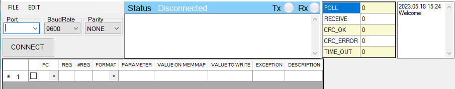
Note: The software only runs on Microsoft Windows OS (win7 and above).
3. Connect the cable and configure the sensor
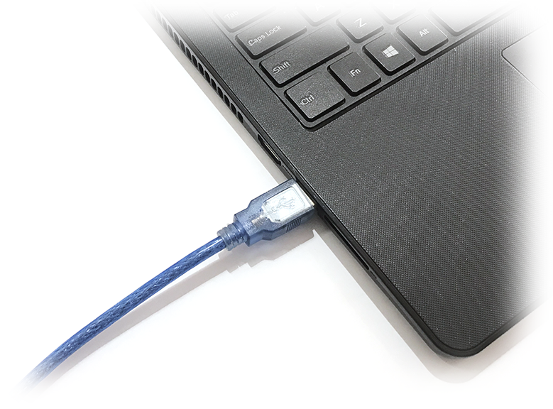
Step 1: Connect USB plug of Modbus configuration cable to USB socket of the PC
|
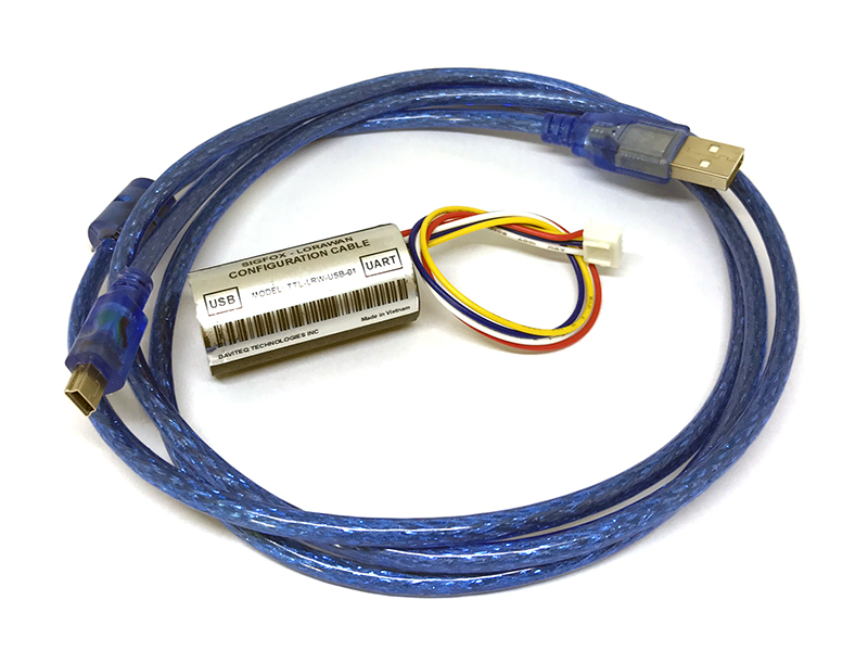
- Use the configuration cable (Item code: TTL-LRW-USB-01). |
- Connect the USB-A plug into the USB-A socket of the PC |
Step 2: On the configuration software, choose the relevant Port (the USB port which is the cable plugged in) and set the BaudRate: 9600, Parity: none
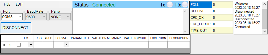
Step 3: Click the “ Connect “ button to connect the software to the sensor. After a successful connection, the connected status(green text) will show on the software.
Step 4: Import the configuration file for the sensor to the software: click menu File/ Import New and then browse the relevant sensor template file (csv file) and click Open to import the template file.
Each sensor type has its own template file. Refer to the sensor's manual to download the correct file.
The sensor is only active for configuration for 60 seconds since plugging the configuration cable or the power supply into the sensor.
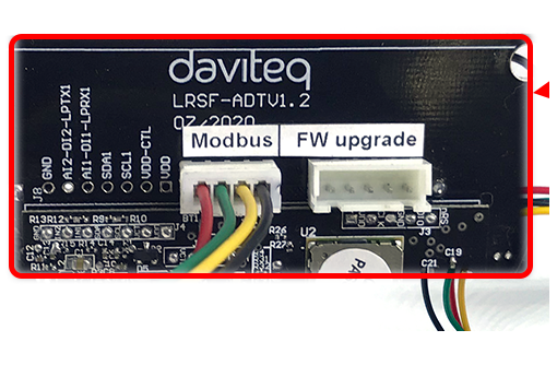
Step 5: Open the housing of the sensor and quickly plug the connector of the configuration cable into sensor's modbus configuration port. After plugging the connector, the software will read the parameter values automatically.
|
- Open the housing of the sensor. |
- Plug the cable connector into sensor's modbus configuration port. Note: this port is located at a different location, depends on the sensor type |

The sensor is only active for configuration for 60 seconds since plugging the configuration cable or the power supply into the sensor.
Step 6: Read the current value of the parameter with function 3
- At the relevant row of the parameter, check box 3 on column FC to read the value of the parameter. The read value is shown on VALUE ON MEMMAP column.
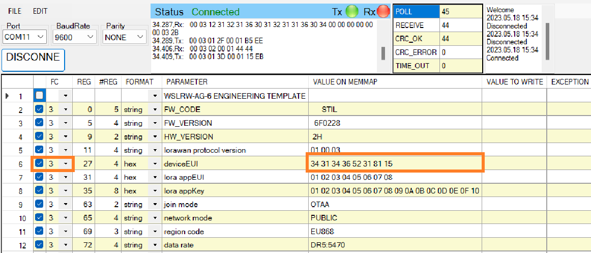
The sensor is only active for configuration for 60 seconds since plugging the configuration cable or the power supply into the sensor. After 60 seconds, the TIME_OUT text will show on EXCEPTION column of the software.
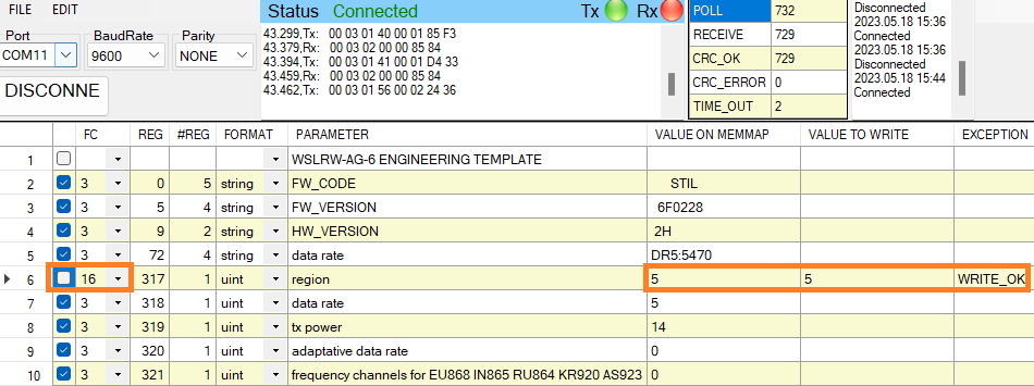
Step 7: Write the new setting to the parameter with function 16
- Double click on the column VALUE TO WRITE of the parameter and input the new setting of the parameter
- Uncheck the tick on the FC column of the parameter, click on the arrow, select 16 and then check on the FC column to write a new setting to the parameter. The WRITE_OK text will show on EXCEPTION column if the software successfully writes the setting.
- Repeat step 6 to read the setting of the parameter for checking.
The sensor is only active for configuration for 60 seconds since plugging the configuration cable or the power supply into the sensor. After 60 seconds, the TIME_OUT text will show on EXCEPTION column of the software.
For some critical parameters of the sensor, the password in "password for setting" must be written before writing the new settings to these parameters.
Only read/write registers are allowed to write.
4. Troubleshooting
|
No. |
Phenomena |
Reason |
Solutions |
|
1 |
The status on the software always shows Disconnected although the configuration cable is connected to the PC |
|
|
|
2 |
The software reads no value after importing the right template and connecting the right cable. |
|
|
|
3 |
No COM port appears in the Port list |
|
|
|
4 |
The parameter table on the software is empty |
|
|
|
5 |
The parameter table on the software does NOT match the memory map table of the sensor. |
|
|
5. List of Configuration Template Files for various Sigfox-Ready Sensors
Please find this link for the template file of each Sigfox-Ready sensor.
END.