USER GUIDE FOR SIGFOX-READY AMMONIA GAS SENSOR WITH BLE WSSFCB-NH3
THIS IS OBSOLETE MANUAL
Please access https://www.iot.daviteq.com/wireless-sensors for updated manual
| WSSFC- NH3-MN-EN-01 |
AUG-2021 |
This document is applied for the following products
| SKU | WSSFCB-NH3 | HW Ver. | 1.1 | FW Ver. |
1.0
|
| Item Code |
WSSFCB-NH3-8-01 |
Wireless Sigfox Ammonia Gas Sensor with BLE, Internal antenna, Type AA battery 1.5VDC, IP67, RC1 zone |
|||
| WSSFCB-NH3-9-01 |
Wireless Sigfox Ammonia Gas Sensor with BLE, Internal antenna, Type AA battery 1.5VDC, IP67, RC2-RC4 zones |
||||
0. Configuration Check List

|
STEP 1: Select RC |
|
|
1. Select RC zone |
RC zones selection 1, 2, 4,... is RCZ1, RCZ2, RCZ4,... (refer to section 6)
|
|
STEP 2: Check ID and PAC |
|
|
Use Modbus Configuration Cable to read the ID and PAC values |
Refer to register address 8 and 10 (DEC) |
|
STEP 3: Configure the sensor's operating parameters |
|
| Configure parameters like cycle send data, alarm, a, b,... | Refer to the configuration section 5 |
|
STEP 4: Add device to Backend Sigfox |
|
| refer to section 5.2 for details | |
|
STEP 5: Installation |
|
| refer to section 8 for details |
1. Functions Change Log
| HW Ver. | FW Ver. | Release Date | Functions Change |
| 1.1 | 1.0 | DEC-2020 |
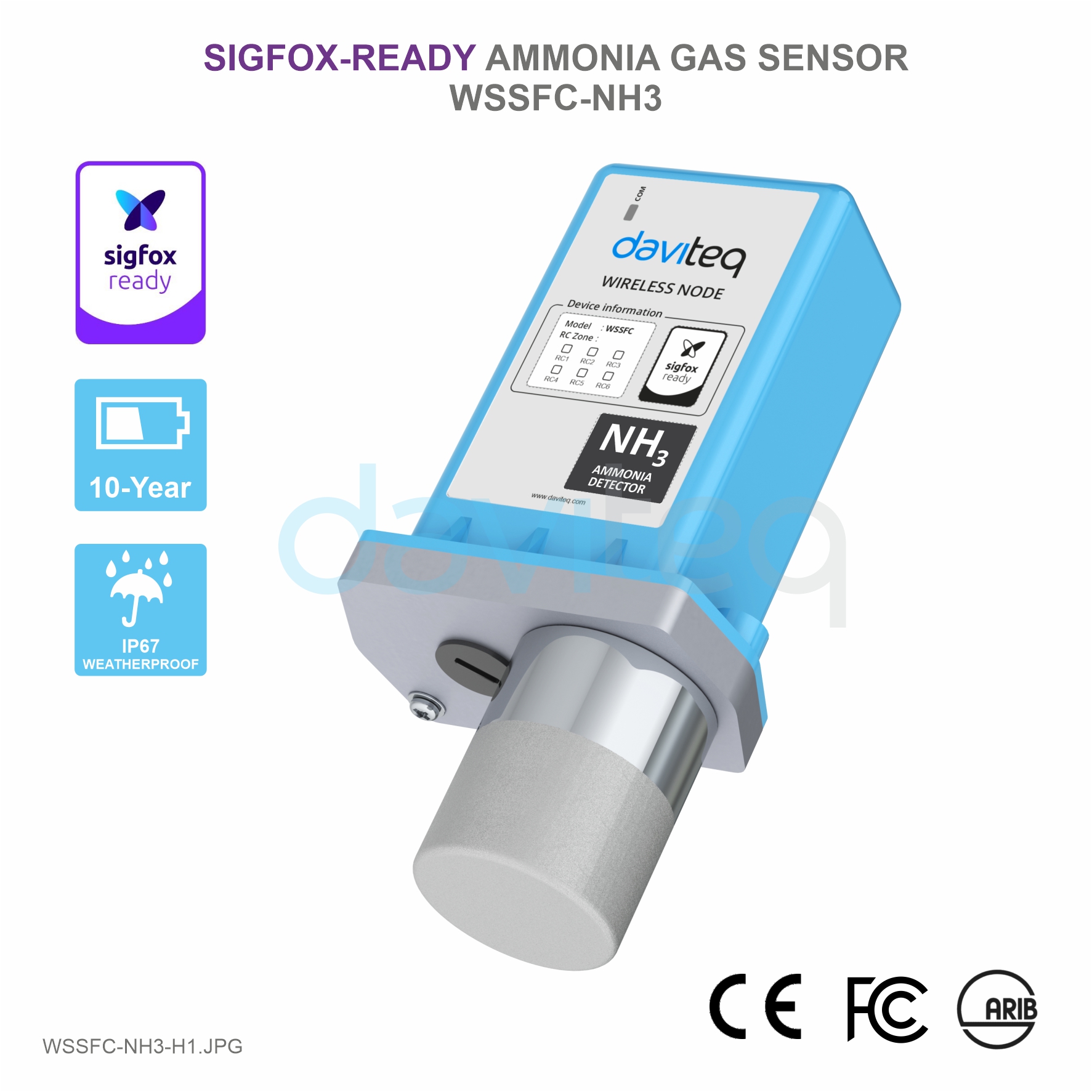
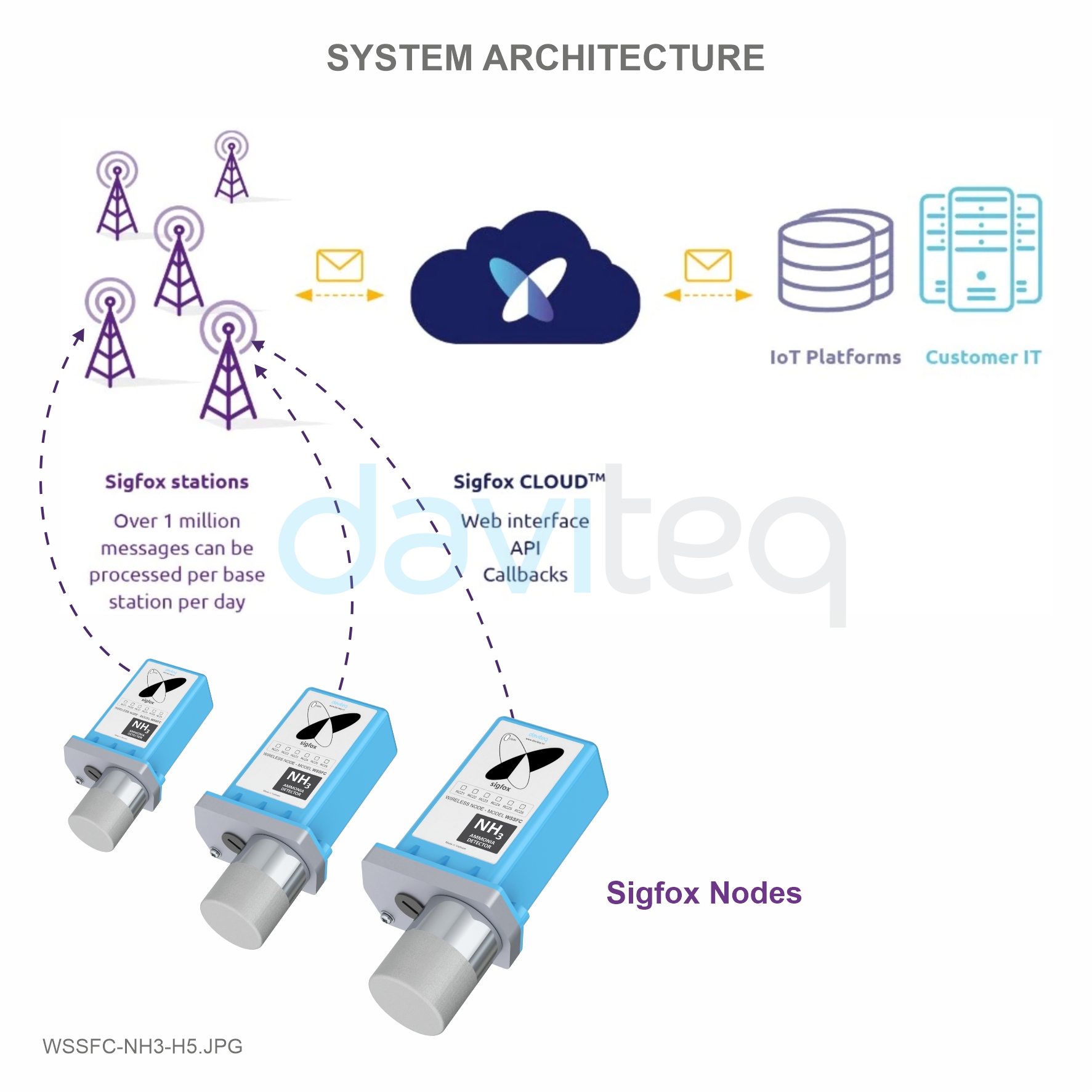
2. Introduction
WSSFC-NH3 is a Sigfox-ready electrochemical-type gas sensor which has high sensitivity to low concentrations of ammonia gas, high selectivity, and a stable baseline. Integrated ambient humidity and temperature so the sensor can be measured by special algorithm expertise through modelling and compensating of external heat sources without the need of any additional components. With Ultra-low power design and smart firmware allow the complete Wireless and Sensor package run on 1 x AA battery 3.6V for 2-5 years with 15 minutes update. It can support all regions of Sigfox network in over the World, RC1, RC2, & RC4.
Typical Applications: Monitor leakage of Ammonia gas for Refrigerator, monitor Ammonia in private or public toilets,...
3. Specification
| SENSORS SPECIFICATION: | |
| NH3 sensor | electrochemical-type gas sensor |
| Measuring range for NH3 | 0..100 ppm |
| Max detecting concentration | 200 ppm |
| Repeatability / Resolution / Stability per month | < 10% of Reading value / 1 ppm / < 2% of Reading value |
| Zero stability | +/- 2 ppm |
| Working atmospheric pressure | 101.3 Kpa +/- 10% |
| Sensor life | > 2 years |
| Humidity and Temperature sensor | Digital type, factory calibrated |
| Humidity measuring range / accuracy / resolution | 0 .. 100 %RH, ± 2.0% / 0.1% |
| Temperature measuring range / accuracy / resolution | -40 .. + 85°C / ± 0.2°C / 0.1°C |
| Working temperature and humidity | -30 .. + 50°C, 15 .. 90% RH |
| Sensor housing / Rating | SS316/SS304 housing with 316SS sintered filter / for Indoor use |
| Sigfox SPECIFICATION: | |
| Sigfox zones | select RC1-RC2-RC4 |
| Antenna | Internal Antenna 2dbi |
| Battery | 02 x AA Type 1.5VDC, working time up to 10 years (depends on configuration) |
| RF Module complies to | CE, FCC, ARIB |
| Working temperature | -40°C..+60°C (using Energizer Lithium Ultimate AA battery) |
| Housing/Protection | Aluminum + Polycarbonate / IP67 |
| Dimension / Net weight | H180xW73xD42 / < 400 grams |
4. Dimensions

5. Operation Principle
Upon power on, the Sigfox node has 60 seconds to wait for off-line configuration (via cable with ModbusRTU protocol)
After 1 minute 30 seconds later the device will send the first data packet and at the same time wait for the downlink packet from the Base Station.
Then during the operation, there are 03 cases of sending data to base station:
1. When the sensor sampling time interval is reached, the Sigfox node will read the data from Input or sensor and performing the calculation. After that it will check calculated value with alarm thresholds. If the calculated was out off the threshold values (Lo or Hi), called alarm, and the number of times of alarm did not pass the limit of number of alarms, then it will send data to Base station immediately;
NOTE:
Once sending the data to base station by this alarm event, the timer of sending time interval will be reset;
2. When the sending time interval is reached, it will send data to Base station immediately, regardless of value;
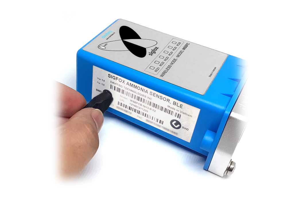
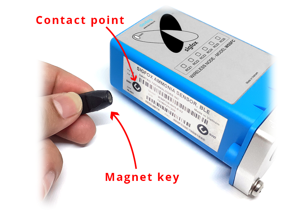
3. By using the magnet key, the Sigfox node can be triggered to send data to base station immediately. There will be a beep sound from the buzzer meaning the data has been sent.

| REED SWITCH | EVENT | PRE-CONDITION | ACTION | LED STATUS | BUZZER STATUS | ACTIVITIES | POST-CONDITION |
| 2 | START_UP | Any state | Move Magnet Key to contact point of REED SWITCH and hold 5s. Buzzer beep 1 long time. |
Blink WHITE | Beep 1 long time | See FW specs | Device reset |
| 1 | FORCE_DATA | Any state | Move Magnet Key to contact point of REED SWITCH. Buzzer beeps 1 time, move Magnet Key away. |
Blink SKY BLUE | Beep 1 time | See FW specs | Back to previous state |
| 1 | PARAMETERS_UPDATE | Any state | Move Magnet Key to contact point of REED SWITCH. Buzzer beeps 1 time, hold Magnet Key 5s. Buzzer beeps 2 times. |
Blink PURPLE | Beep 2 times | See FW specs | Back to previous state |
NOTE:
Once sending the data to base station by the magnet key, the timer of sending time interval will be reset;
The shortest time interval between the two manual triggers is 5s. if shorter than 5s, there will be no data sending.
 |
 |
5.1 RC technical details
The RF transmit power will be automatically set as the max value as allowed by the Zone.
Sigfox Radio Configuration (RC) defines the radio parameters in which the device shall operate: Sigfox operating frequencies, output power, spectrum access mechanism, throughput, coexistence with other radio technologies, etc.
Each radio configuration includes 4 uplink classes: 0u, 1u, 2u, and 3u.
The Sigfox network globally works within the ranges from 862 to 928 MHz. But not all RCs require such a wide range of operation.
| RC1 | RC2 | RC3 | RC4 | RC5 | RC6 | RC7 | |
|---|---|---|---|---|---|---|---|
| Uplink center frequency (MHz) | 868.130 | 902.200 | 923.200 | 920.800 | 923.300 | 865.200 | 868.800 |
| Downlink center frequency (MHz) | 869.525 | 905.200 | 922.200 | 922.300 | 922.300 | 866.300 | 869.100 |
| Uplink data rate (bit/s) | 100 | 600 | 100 | 600 | 100 | 100 | 100 |
| Downlink data rate (bit/s) | 600 | 600 | 600 | 600 | 600 | 600 | 600 |
| Sigfox recommended EIRP (dBm) | 16 | 24 | 16 | 24 | 14 | 16 | 16 |
| Specifics | Duty cycle 1% * | Frequency hopping ** | Listen Before Talk *** | Frequency hopping ** | Listen Before Talk *** | Duty cycle 1% * |
* Duty cycle is 1% of the time per hour (36 seconds). For an 8 to 12 bytes payload, this means 6 messages per hour, 140 per day.
** Frequency hopping: The device broadcasts each message 3 times on 3 different frequencies. Maximum On time 400 ms per channel. No new emission before 20 s.
*** Listen Before Talk: Devices must verify that the Sigfox-operated 200 kHz channel is free of any signal stronger than −80 dBm before transmitting.
Sigfox’s high limit EIRP recommendation is included in each column although regulations sometimes allow for more radiated power than the Sigfox recommendation.
Sigfox’s recommendation is set to comply with the Sigfox technological approach of:
- Low current consumption
- Balanced link budget between uplink and downlink communication
5.2 Add a device to the Backend Sigfox
Step 1: Log in to the sigfox backend website

Step 2: Click on Device

Step 3: Click New → Select a group
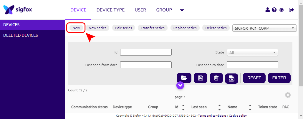
Step 4: Fill in the required information
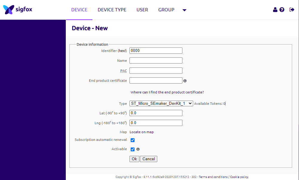
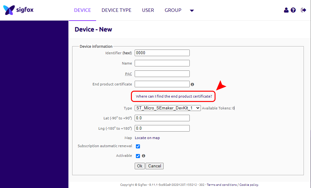
Note: Some of our products may not have end product certification in time, to add the product to Backend Sigfox please follow the steps below.
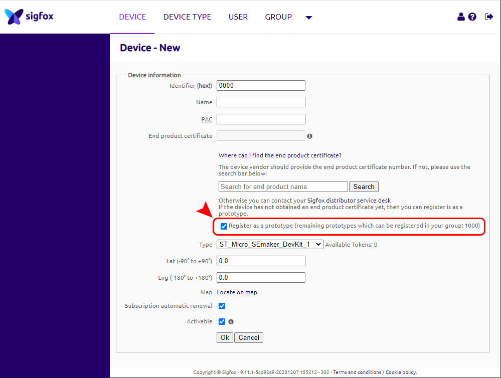
Click on the text as shown below
Check the box as shown below to register as a prototype
5.3 Device behavior & Firmware Specification of NH3 Sensor
Please read sections 5.5 to 5.8 carefully for a better understanding of the configuration
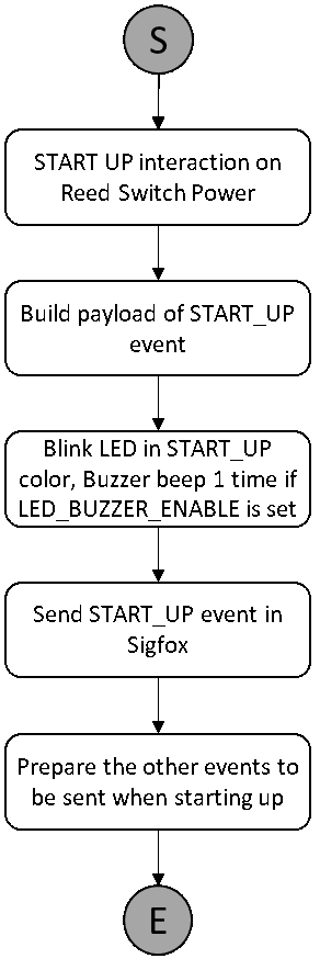
5.3.1 Start-up features
5.3.1.1 Payload fields
- EVENT_TYPE
5.3.1.2 Description
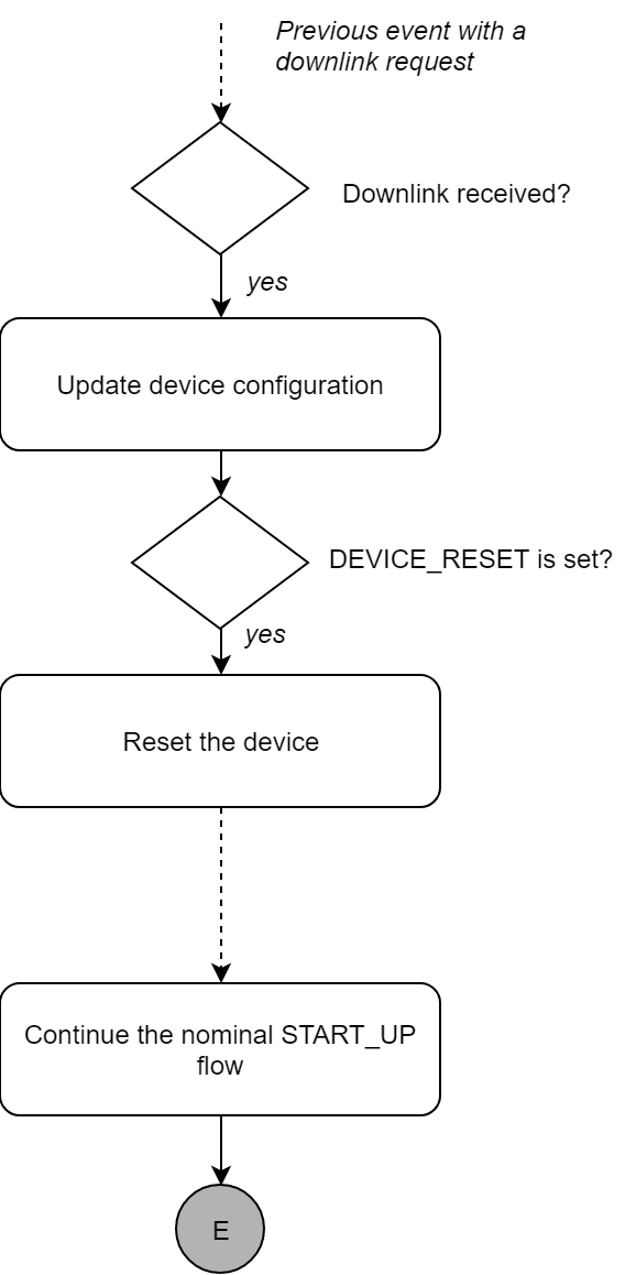
START_UP event is prepared every time the device is starting up. It can be either if the device is starting for the first time, or when the device is being reset. The device can be reset by two possible ways, one is thanks to the reed power switch , the other thanks to the DEVICE_RESET flag set in a downlink message.
5.3.1.3 Frame

5.3.1.4 Flowchart
- Nominal flow:
- Flow when coming from downlink:
5.3.2 Heartbeat feature
5.3.2.1 Parameters
- HEARTBEAT_PERIOD
5.3.2.2 Payload fields
- EVENT_TYPE
- HW_VERSION
- FW_VERSION
- LATEST_SIGFOX_DOWNLINK
5.3.2.3 Description
HEARTBEAT event is prepared every HEARTBEAT_PERIOD. When the uplink message of the HEARTBEAT event is prepared, the latest valid configuration that the device has received is provided through the LATEST_SIGFOX_DOWNLINK field.
The HEARTBEAT event is a Sigfox downlink exchange. Thanks to the downlink message, pre-defined parameters of the device can be modified in order to change the device behavior.
5.3.2.4 Frame

5.3.2.5 Flowchart

5.3.3 Parameters update feature
5.3.3.1 Payload fields
- EVENT_TYPE
- LATEST_SIGFOX_DOWNLINK
5.3.3.2 Description
When the appropriate action is done by the user on the Reed Switch 2, a PARAMETERS_UPDATE event is generated. When the uplink message of the PARAMETERS_UPDATE event is prepared, the latest valid configuration that the device has received is provided through the LATEST_SIGFOX_DOWNLINK field.
The PARAMETERS_UPDATE event is a Sigfox downlink exchange. Thanks to the downlink message, pre-defined parameters of the device can be modified in order to change the device behavior.
5.3.3.3 Frame
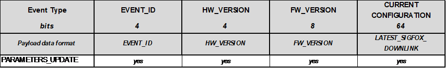
5.3.3.4 Flowchart

5.3.4 NH3 feature
5.3.4.1 Parameters (DLK)
For NH3 measurement
- NH3_ENABLE
- NH3_MEASURE_PERIOD
For NH3 message feature
- NH3_EVENT_ENABLE
- NH3_EVENT_PERIOD
For ALERT feature
- NH3_ALERT_ENABLE
- NH3_ALERT1_MAX_THRESHOLD
- NH3_ALERT2_MAX_THRESHOLD
For BLE advertizing
- ALERT_FLAG_reset
- BLE_BROADCAST_ENABLE
- BROADCAST_PERIOD_normal (TBC)
- BROADCAST_PERIOD_alert(TBC)
- BLE_RF_OUTPUT_POWER
5.3.4.2 Payload fields
- EVENT_ID
- …
5.3.4.3 Description
- NH3 SENSING and EVENT
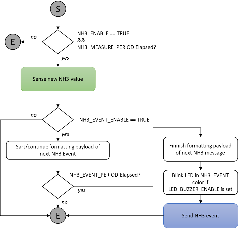
The NH3 sensing is enabled thanks to the NH3_ENABLE flag.
The NH3 event is enabled thanks to the NH3_EVENT_ENABLE flag.
New NH3 values are taken every NH3_MEASURE_PERIOD.
NH3 event is prepared every NH3_EVENT_PERIOD. Before sending the event, all statistics (minimum, average and maximum for NH3 levels) are computed since the last NH3 event.
- NH3 ALERT
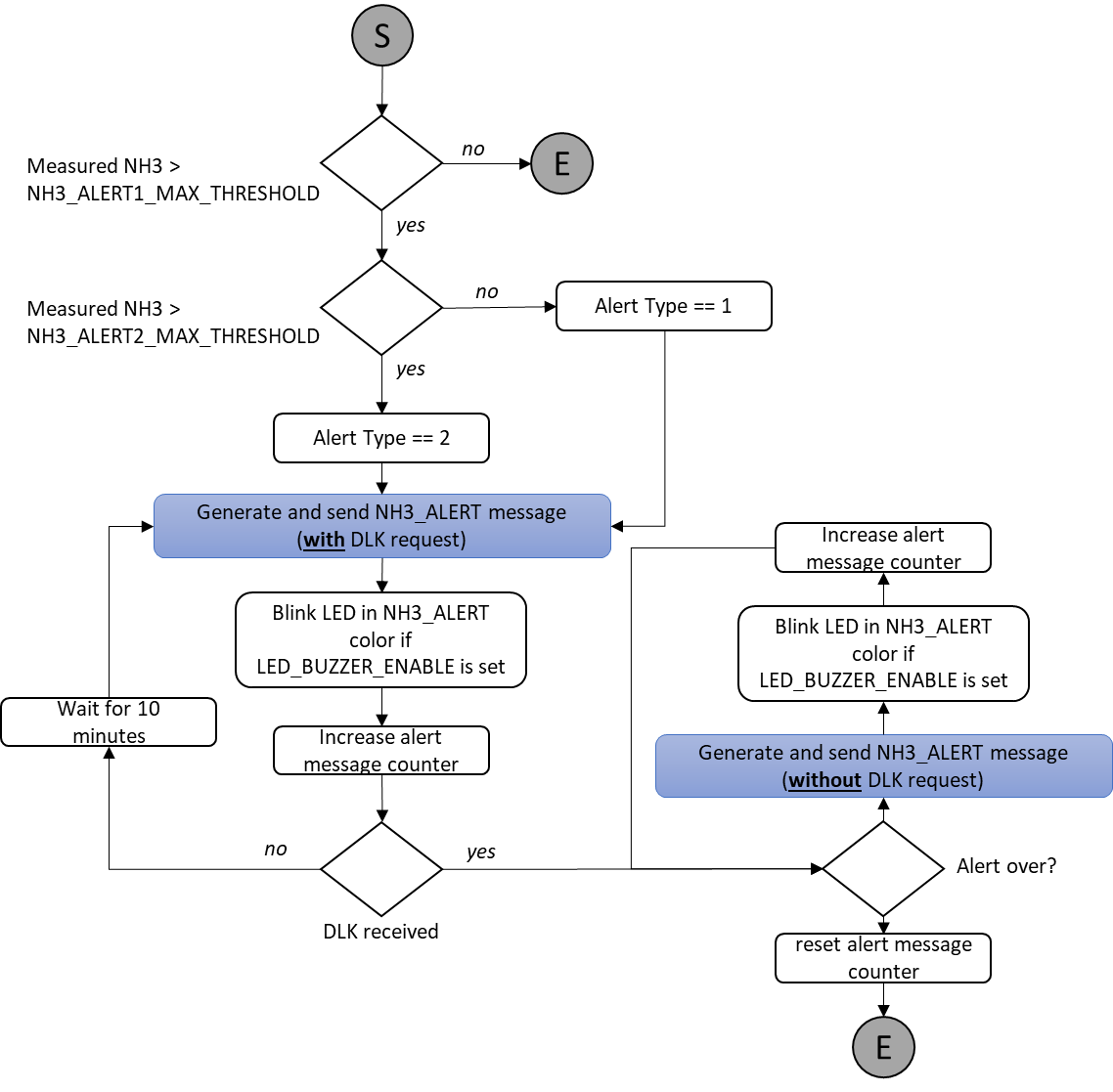
The NH3 alert feature is enabled thanks to the NH3_ALERT_ENABLE flag.
The NH3 sensing check against NH3_ALERT1_MAX_THRESHOLD and NH3_ALERT2_MAX_THRESHOLD, is done anytime a NH3 measurement is performed.
If the check reports that the measured level is above NH3_ALERT1_MAX_THRESHOLD or NH3_ALERT2_MAX_THRESHOLD, an ALERT procedure will start. The NH3 measured value will be recorded during the alert as well as the alert duration.
The ALERT message will be sent right after the alert is detected with a DLK request. When alert message is received at Sigfox server, this will initiate to send an available downlink (DLK) at Sigfox server to device.
The message will be sent again until a DLK is received every 10 minutes and until the level goes back to a normal level.
After a DLK is received, the device will keep sending Alert message every 10 minutes until the alert is over.
During the ALERT procedure, all other Sigfox events are cancelled. Only NH3 measurements is performed and BLE advertising are maintained.
- BLE advertising
When the BLE_BROADCAST_ENABLE flag is set to true, the device will broadcast a BLE beacon signal. The signal broadcasted will change according to the following rules:
The BLE NORMAL frame is broadcasted every BROADCAST_PERIOD_normal when the alert_type flag is set to 0.
The BLE ALERT 1 frame is broadcasted every BROADCAST_PERIOD_alert when the alert_type flag is set to 1.
The BLE ALERT 2 frame is broadcasted every BROADCAST_PERIOD_alert when the alert_type flag is set to 2.
5.3.4.4 Frames


5.3.4.5 Flowchart
-
Sigfox Normal mode
- Sigfox Alert mode
If the message counter reaches a value above the maximum possible tentative field value (255) in the NH3_ALERT message, the tentative value should be kept at the maximum (255).
- BLE broadcast


- BLE broadcast format
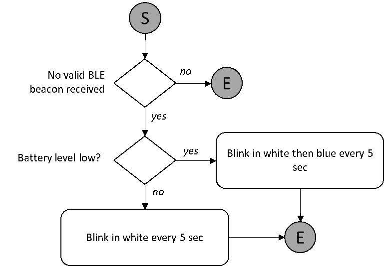
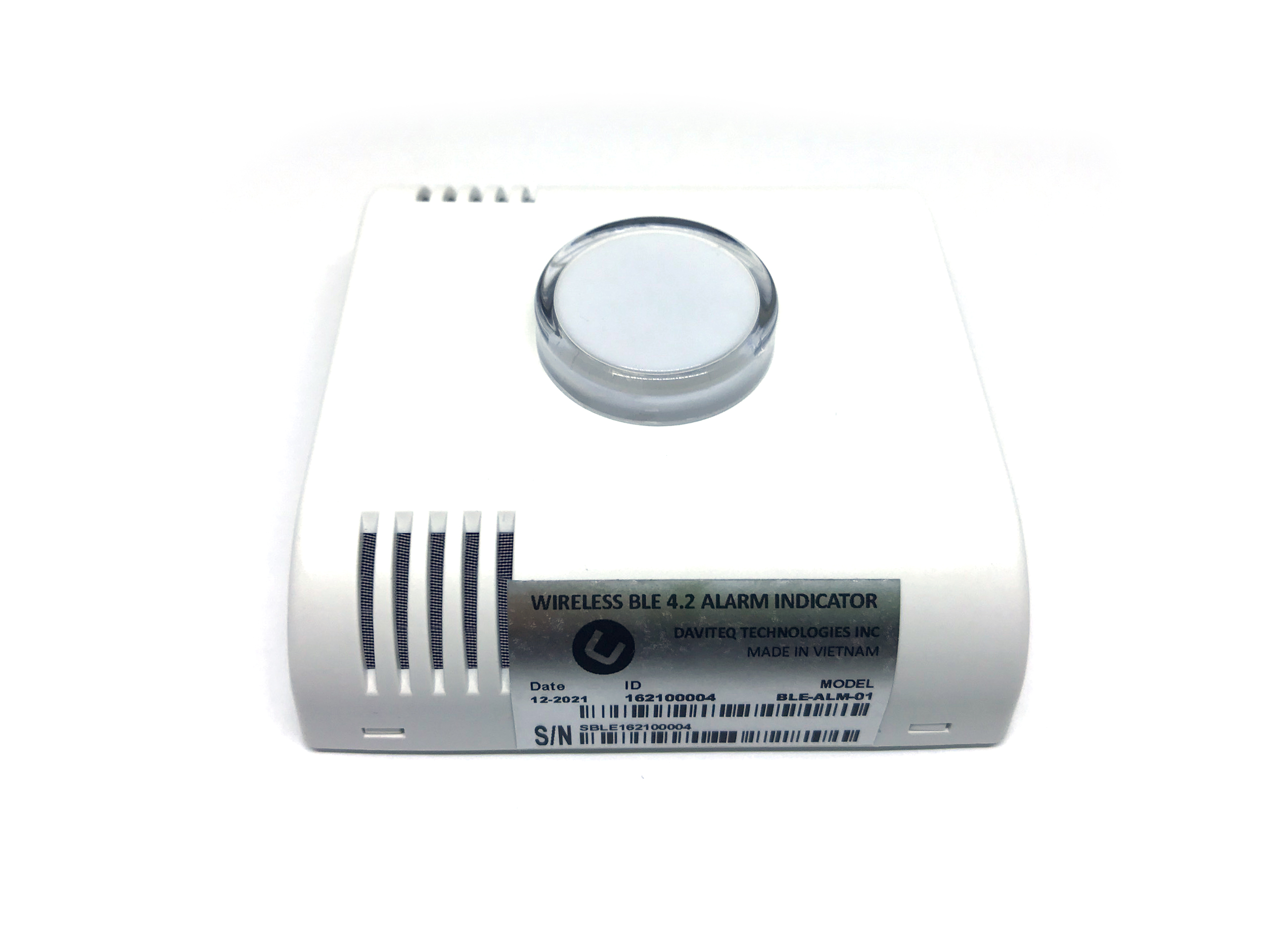
5.4 Light and sound indicator
The light indicator is always in RF listening mode and searching for a beacon signal from the sensor it is attached to.
The indicator device will be able to identify the beacon signal transmitted by the NH3 sensor it is attached to and only consider the beacon signal from that specific sensor.
Some simple synchronization mechanisms will be implemented in order to minimize the power consumption of the receiver to an acceptable level.
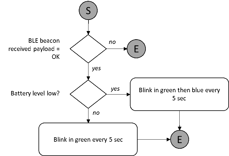
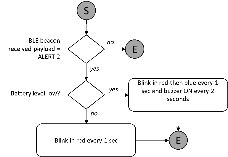
Depending on the beacon received, the indicator device will have the behavior described in the following flowcharts:
No Signal:
Signal received « OK »:
Signal received « ALERT 1 »:

Signal received « ALERT 2 »:
5.5 Pairing with BLE Indicator
Insert the batteries into Sigfox NH3-BLE device, wait 1 minute for configuration stage end, then Sigfox NH3-BLE will broadcast BLE data.
Then insert the batteries into BLE Indicator, place it near to Sigfox NH3BLE
- When BLE Indicator has got ID NOT MATCH with ID from Sigfox NH3-BLE, BLE Indicator will beep 2 times. So you need to clear that ID before pairing the BLE Indicator with the new Sigfox device. To clear the ID in BLE Indicator, place magnet key to reed switch area (marked as a magnet on the nameplate), the BLE indicator will beep 1 time, and the status led (the led on side of the board) blink WHITE.
It is recommended that when adding an ID to a BLE Indicator you should clear the ID first.
- After clearing the ID of the BLE Indicator, you may wait for up to 1 minute for it to pair with the new Sigfox device. When pairing is successful, you can hear 1 beep sound;
- When BLE Indicator have ID MATCH with ID from Sigfox NH3BLE , BLE Indicator will operation normal (details in Firmware Specifications Sound and light indicator)
5.6 Event ID
| Event Type bits |
EVENT_ID 4 |
COLOR |
| START_UP | 0 | WHITE |
| HEARTBEAT | 1 | GREEN |
| PARAMETERS_UPDATE | 2 | PURPLE |
| NH3_FORCE_DATA | 3 | SKY BLUE |
| NH3 | 4 | SKY BLUE |
| NH3_ALERT | 5 | RED |
| Not used | 6 | |
| Not used | 7 | |
| Not used | 8 | |
| Not used | 9 | |
| Not used | 10 | |
| Not used | 11 | |
| Not used | 12 | |
| Not used | 13 | |
| Not used | 14 | |
| Not used | 15 |
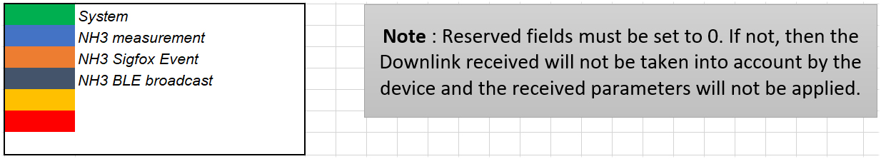
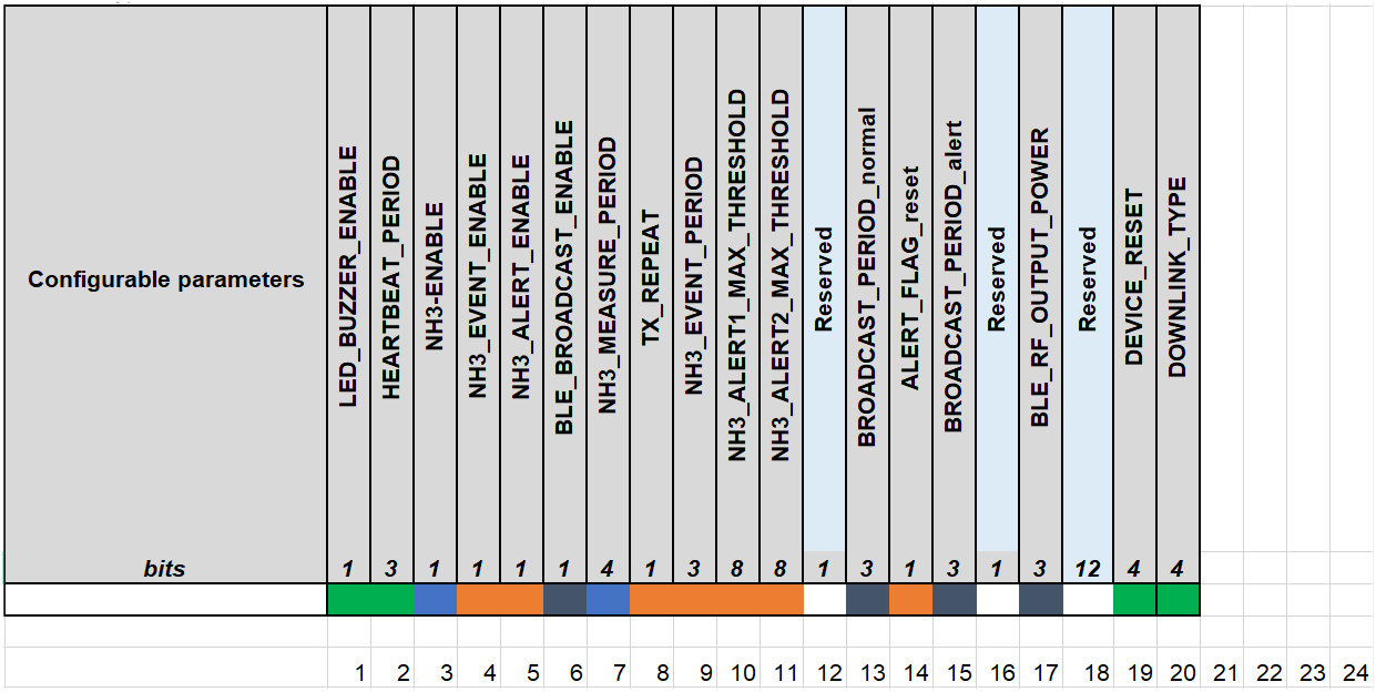
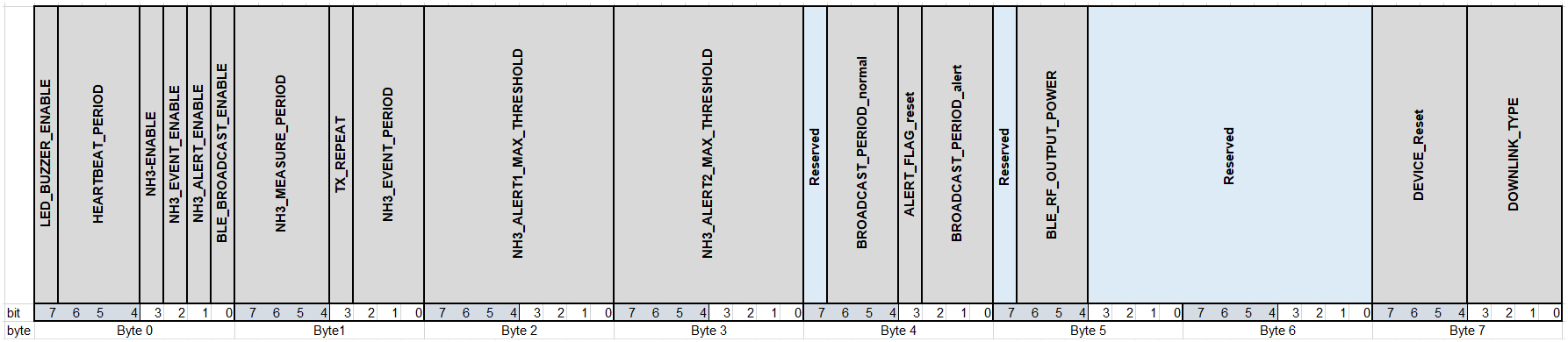
5.7 Configuration Parameters
Should not change the value in the Blue cells
| Category | Parameter | Description | Possible values | Default value | Length (in bits) |
| DEVICE | LED_BUZZER_ENABLE | Flag to enable/disable LED and Buzzer interactions for action not triggered by the button. | 0b0 = false, LEDs are OFF 0b1 = true, LEDs are ON |
0b0 = false | 1 |
| DEVICE | DEVICE_RESET | Once this parameter is set, the device shall restart once after having received the DL. | 0b1010 = 0xA = Force device reset others = do nothing |
others = do nothing | 4 |
| DEVICE | TX_REPEAT | Number of Sigfox frames | 0b0 = 1 frames 0b1 = 3 frames |
0b0 = 1 frames | 1 |
| HEARTBEAT | HEARTBEAT_PERIOD | Period of time to send HEARTBEAT event | 0b000 = every 1h 0b001 = every 6h 0b010 = every 12h 0b011 = every 24h (1 day) 0b100 = every 48h (2 day) 0b101 = every 72h (3 day) 0b110 = every 120h (5 day) 0b111 = every 240h (10 day) |
0b100= every 48h (2 days) | 3 |
| NH3 | NH3_ENABLE | Enable NH3 sensing | 0b0 = false, NH3 sensing is disabled 0b1 = true, NH3 sensing is enabled |
0b1 = true | 1 |
| NH3 | NH3_MEASURE_PERIOD | Interval of time between two consecutive NH3 values are acquired | 0b0000 = every 1s 0b0001 = every 2s 0b0010 = every 5s 0b0011 = every 10s 0b0100 = every 20s 0b0101 = every 30s 0b0110 = every 1min 0b0111 = every 2min 0b1000 = every 5min 0b1001 = every 10min 0b1010 = every 20min 0b1011 = every 30min 0b1100 = every 1h 0b1101 = every 2h 0b1110 = every 3h 0b1111 = every 6h |
0b0010 = every 5s | 4 |
| NH3 | NH3_EVENT_ENABLE | Enable NH3 event | 0b0 = false, NH3 event is disabled 0b1 = true, NH3 event is enabled |
0b1 = true | 1 |
| NH3 | NH3_EVENT_PERIOD | Interval of time between two consecutive NH3 events | 0b000 = every 10min 0b001 = every 30min 0b010 = every 1h 0b011 = every 2h 0b100 = every 3h 0b101 = every 6h 0b110 = every 12h 0b111 = every 24h |
0b010 = every 1h | 3 |
| NH3 | NH3_ALERT ENABLE | Enable NH3_ALERT event | 0b0 = false, NH3 ALERT feature is disabled 0b1 = true, NH3 ALERT feature is enabled |
0b0 = false, NH3 ALERT feature is disabled | 1 |
| NH3 | NH3_ALERT1_MAX_THRESHOLD | Threshold #1 on the temperature to trig a NH3_ALERT event | 8-bit unsigned integer Formula: (8-bit_NH3ppm*2)= real_NH3_level_in_ppm Range: 0 to 100ppm Accuracy: 0.5ppm Example: 0b01110100 = 0x74 = 116 => (116 / 2) = 58ppm |
0b00001010 = 5ppm | 8 |
| NH3 | NH3_ALERT2_MAX_THRESHOLD | Threshold #2on the temperature to trig a NH3_ALERT event | 8-bit unsigned integer Formula: (8-bit_NH3ppm*2)= real_NH3_level_in_ppm Range: 0 to 100ppm Accuracy: 0.5ppm Example: 0b01110100 = 0x74 = 116 => (116 / 2) = 58ppm |
0b00010100 = 10ppm | 8 |
| NH3 | ALERT_FLAG_reset | Flag to reset the BLE broadcast mechanism and set it back to normal. | 0b1010 = 0xA = leave BLE alert mode others = do nothing |
others = do nothing | 1 |
| BLE | BLE_BROADCAST_ENABLE | Enable BLE advertising functionality | 0b0 = false, BLE advertising feature is disabled 0b1 = true, BLE advertising feature is enabled |
0b1 = true, BLE advertising feature is enabled | 1 |
| BLE | BROADCAST_PERIOD_normal | Broacasting period when the device is in normal mode | 0b000 = every 1s 0b001 = every 2s 0b010 = every 5s 0b011 = every 10s 0b100 = every 30s 0b101 = every 1 min 0b110 = every 2 min 0b111 = every 5 min |
0b011 = every 10s | 3 |
| BLE | BROADCAST_PERIOD_alert | Broacasting period when the device is in alert mode | 0b000 = every 1s 0b001 = every 2s 0b010 = every 5s 0b011 = every 10s 0b100 = every 30s 0b101 = every 1 min 0b110 = every 2 min 0b111 = every 5 min |
0b001 = every 2s | 3 |
| BLE | BLE_RF_OUTPUT_POWER | Transmit power level | 0b000 = -20dBm 0b001 = -10dBm 0b010 = 0dBm 0b011 = 5dBm |
0b000 = -20dBm | 3 |
5.8 Payload Data
The following is the format of payload data that will be sent to the Sigfox server.
5.8.1 Payload Fields
| Category | Data name | Description | Encoding or Possible values | Length (in bits) |
| DEVICE | EVENT_ID | Unique ID identifying the device event | 4-bit unsigned integer Possible values: As defined in Event ID tab |
4 |
| DEVICE | LATEST_SIGFOX_DOWNLINK | The Latest received and valid Sigfox downlink frame | 64-bit encoded field See Sigfox Downlink tab |
64 |
| DEVICE | HW_VERSION | Indicate HW version | 4-bit unsigned integer HW_VERSION = HW_VERSION value in EEPROM set in production if Value unknown, default value will be 0 |
4 |
| DEVICE | FW_VERSION | indicate FW version | 8-bit unsigned integer Refer to FW release note |
8 |
| NH3 | NH3 | NH3 level of the surrounding environment of the device | 16-bit unsigned integer Formula: (16-bit_NH3ppm/100)= real_NH3_level_in_ppm Range: 0 to 100ppm Accuracy: 0.01ppm Example: 0x16B7 = 5815 => (5815 / 100) = 58.15ppm |
16 |
| Type | ALERT_TYPE | Type of alert | 2-bit unsigned integer 0b0 = Not used 0b1 = Alert type 1 0b10 = Alert type 2 0b11 = Not used |
2 |
| TIME | ALERT_DURATION | Alert duration in hours | 8-bit unsigned integer Formula: 8-bit_Alert_duration = real_TempAlert_duration_in_hours Range: 0 to 255 hours Accuracy: 1 hour Example: 0b00100000 = 0x20 = 32 => 32 hours |
8 |
| Tentative | TENTATIVE | Tentative number | 8-bit unsigned integer Formula: (8-bit_Tentativve +1)= real_tentative # Range: 1 to 256 Accuracy: 1 Example: 0b00000111 = 0x7=7=> 7+1 =>tentative # 8 |
8 |
5.8.2 Sigfox Uplink Frame Format
For more details, you can download the file HERE
| Size | |||||
| Event Type | EVENT_ID | HW_VERSION | FW_VERSION | CURRENT CONFIGURATION | |
| 10.0 | bits | 4 | 4 | 8 | 64 |
| Payload data format | EVENT_ID | HW_VERSION | FW_VERSION | LATEST_SIGFOX_ DOWNLINK |
|
| START_UP | yes | yes | yes | yes | |
| Event Type | EVENT_ID | HW_VERSION | FW_VERSION | CURRENT CONFIGURATION | |
| 10.0 | bits | 4 | 4 | 8 | 64 |
| Payload data format | EVENT_ID | HW_VERSION | FW_VERSION | LATEST_SIGFOX_ DOWNLINK |
|
| HEARTBEAT | yes | yes | yes | yes | |
| Event Type | EVENT_ID | HW_VERSION | FW_VERSION | CURRENT CONFIGURATION | |
| 10.0 | bits | 4 | 4 | 8 | 64 |
| Payload data format | EVENT_ID | HW_VERSION | FW_VERSION | LATEST_SIGFOX_ DOWNLINK |
|
| PARAMETERS_UPDATE | yes | yes | yes | yes | |
| Event Type | EVENT_ID | HW_NH3_ERROR | RESERVED | NH3 | |
| 3.0 | bits | 4 | 1 | 3 | 16 |
| Payload data format | EVENT_ID | HW_NH3_ERROR | - | NH3 | |
| NH3_FORCE_DATA | yes | yes | zeros | yes |
| Event Type | EVENT_ID | HW_NH3_ERROR | RESERVED | NH3 | MIN_NH3 | AVG_NH3 | MAX_NH3 | |
| 9.0 | bits | 4 | 1 | 3 | 16 | 16 | 16 | 16 |
| Payload data format | EVENT_ID | HW_NH3_ERROR | - | NH3 | NH3 | NH3 | NH3 | |
| NH3 | yes | yes | zeros | yes | yes | yes | yes | |
| Event Type | EVENT_ID | HW_NH3_ERROR | RESERVED | ALERT_TYPE | EXTREME_NH3 | ALERT_ DURATION |
TENTATIVE | |
| 5.0 | bits | 4 | 1 | 1 | 2 | 16 | 8 | 8 |
| Payload data format | EVENT_ID | HW_NH3_ERROR | - | ALERT_TYPE | NH3 | ALERT_ DURATION |
TENTATIVE | |
| NH3_ALERT | yes | yes | zeros | yes | yes | yes | yes |
5.8.3 Sigfox Downlink Frame Format.
The Sigfox node is only able to receive max 04 downlinks a day, each downlink will be waiting in every 06 hours.
User can set the down link data in Sigfox back-end system in advance, whenever the Sigfox node connected to base stations and with downlink waiting is enable at that time (one time in 6 hours), the downlink data will be loaded to Sigfox node.
The downlink data can be any configuration parameter.
Please pay attention when send downlink data. If there was a mistake in sending wrong data, it would cause the Sigfox node not working properly and user need to configure it by offline cable!!!
For more details, you can download the file HERE
Downlink Frame Format:
Downlink type= 0b0000
Downlink type= 0b0101
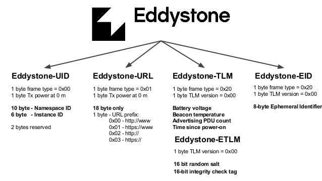
5.9 BLE Broadcast Format
| Size | ||||||||||
| Broadcast Type | EDDYSTONE HEADER | DEVICE_ID | ALERT_TYPE |
ALERT_ FLAG_ reset |
HW_ NH3_ ERROR |
HW_ VERSION |
FW_ VERSION |
CURRENT CONFIGURATION | NH3 | |
| 28.0 | bits | 96 | 32 | 2 | 1 | 1 | 4 | 8 | 64 | 16 |
| Payload data format | EDDYSTONE HEADER | DEVICE_ID | ALERT_TYPE |
ALERT_ FLAG_ reset |
HW_ NH3_ ERROR |
HW_ VERSION |
FW_ VERSION |
LATEST_ SIGFOX_ DOWNLINK |
NH3 | |
| BLE Broadcast: OK ALERT_TYPE = 0 |
0x0201040303AAFEXX16AAFE20 | yes | yes | yes | yes | yes | yes | yes | yes |
| Size | ||||||||||
| Broadcast Type | EDDYSTONE HEADER | DEVICE_ID | ALERT_TYPE |
ALERT_ FLAG_ reset |
HW_ NH3_ ERROR |
HW_ VERSION |
FW_ VERSION |
CURRENT CONFIGURATION | NH3 | |
| 28.0 | bits | 96 | 32 | 2 | 1 | 1 | 4 | 8 | 64 | 16 |
| Payload data format | EDDYSTONE HEADER | DEVICE_ID | ALERT_TYPE |
ALERT_ FLAG_ reset |
HW_ NH3_ ERROR |
HW_ VERSION |
FW_ VERSION |
LATEST_ SIGFOX_ DOWNLINK |
NH3 | |
| BLE Broadcast: OK ALERT_TYPE = 1 or 2 ALERT_FLAG_reset = 1 |
0x0201040303AAFEXX16AAFE20 | yes | yes | yes | yes | yes | yes | yes | yes |
| Size | ||||||||||
| Broadcast Type | EDDYSTONE HEADER | DEVICE_ID | ALERT_TYPE |
ALERT_ FLAG_ reset |
HW_ NH3_ ERROR |
HW_ VERSION |
FW_ VERSION |
CURRENT CONFIGURATION | NH3 | |
| 28.0 | bits | 96 | 32 | 2 | 1 | 1 | 4 | 8 | 64 | 16 |
| Payload data format | EDDYSTONE HEADER | DEVICE_ID | ALERT_TYPE |
ALERT_ FLAG_ reset |
HW_ NH3_ ERROR |
HW_ VERSION |
FW_ VERSION |
LATEST_ SIGFOX_ DOWNLINK |
NH3 | |
| BLE Broadcast: ALERT 1 ALERT_TYPE = 1 ALERT_FLAG_reset = 0 |
0x0201040303AAFEXX16AAFE20 | yes | yes | yes | yes | yes | yes | yes | yes |
| Size | ||||||||||
| Broadcast Type | EDDYSTONE HEADER | DEVICE_ID | ALERT_TYPE |
ALERT_ FLAG_ reset |
HW_ NH3_ ERROR |
HW_ VERSION |
FW_ VERSION |
CURRENT CONFIGURATION | NH3 | |
| 28.0 | bits | 96 | 32 | 2 | 1 | 1 | 4 | 8 | 64 | 16 |
| Payload data format | EDDYSTONE HEADER | DEVICE_ID | ALERT_TYPE |
ALERT_ FLAG_ reset |
HW_ NH3_ ERROR |
HW_VERSION | FW_VERSION |
LATEST_ SIGFOX_ DOWNLINK |
NH3 | |
| BLE Broadcast: ALERT 2 ALERT_TYPE = 2 ALERT_FLAG_reset = 0 |
0x0201040303AAFEXX16AAFE20 | yes | yes | yes | yes | yes | yes | yes | yes |
6. Modbus Memmap
6.1 Data table
| Modbus Register (Decimal) | Modbus Register (Hex) | Function Code | # of Registers | Description | Range | Default | Format | Property | Comment |
| 2 | 2 | 3 | 4 | firmware version | string | Read | |||
| 6 | 6 | 3 | 2 | hardware version | string | Read | |||
| 8 | 8 | 3 | 2 | device ID | hex | Read | Product ID | ||
| 10 | A | 3 | 4 | device PAC | hex | Read | Product PAC | ||
| 14 | E | 3 | 1 | SENSOR_TYPE | 1-255 | uint16 | Read | Sensor or Input Type |
6.2 Configuration table
| Modbus Register (Decimal) | Modbus Register (Hex) |
Function Code (Read) |
Function Code (Write) |
# of Registers | Description | Range | Default | Format | Property | Comment |
| 270 | 10E | 3 | 16 | 4 | CURRENT_CONFIGURATION | hex | Read/Write | |||
| 274 | 112 | 3 | 16 | 1 | SERVER_CONFIG | uint16 | Read / Write | 0: Send to Sigfox Network 1: Send to Dongle |
||
| 276 | 114 | 3 | 16 | 1 | RADIO_CONFIG | 1, 2, 4 | 4 | uint16 | Read / Write | RC zones selection 1, 2 ,4 is RCZ1, RCZ2, RCZ4 |
| 277 | 115 | 3 | 16 | 1 | TX_POWER | 20 | int16 | Read / Write | RF Tx power | |
| 278 | 116 | 3 | 16 | 2 | CONSTANT_A | 1 | float | Read / Write | Constant a for scaling measured value | |
| 280 | 118 | 3 | 16 | 2 | CONSTANT_B | 0 | float | Read / Write | Constant b for scaling measured value | |
| 282 | 11A | 3 | 16 | 2 | HIGH_CUT | 1E+09 | float | Read / Write | High cut value for calculated value | |
| 284 | 11C | 3 | 16 | 2 | LOW_CUT | -1E+09 | float | Read / Write | Low cut value for calculated value | |
| 286 | 11E | 3 | 16 | 2 | SENSOR_BOOT_TIME | 200 | uint32 | Read / Write | Boot time of sensor/input, in ms | |
| 306 | 132 | 3 | 16 | 2 | SYSTEM_SENSITIVITY | 11 | float | Read / Write | The sensitivity of the circuit (mV/ppm) |
7. Offline configuration
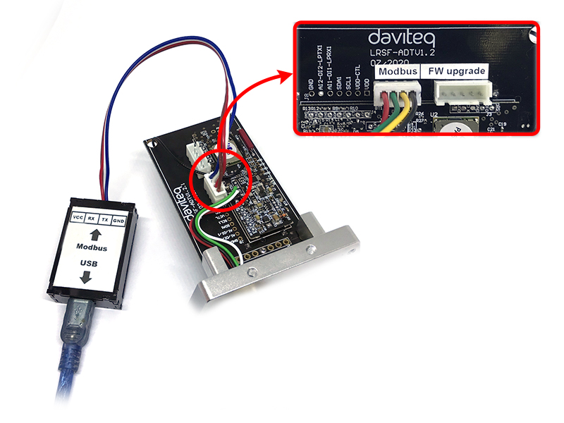
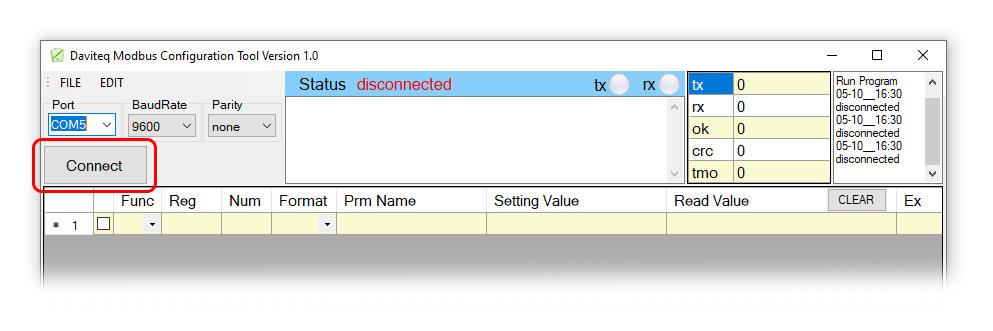
Using the configuration cable to connect to the sensor as below picture.
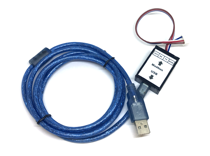
Serial port configuration on computer: 9600 baud, None parity, 1 stop bit.
Reading data by Function 3.
Writing data by Function 16.
During connection with Modbus configuration tool, the Sigfox node will send all data in realtime: Battery, Battery level, Vref, Button status, reed switch status, PCB temperature, Measured value, alarm status.
Step to configure & check data:
NOTE:
The Modbus configuration can be done in the first 60s after power up the Sigfox node. After 60s, if user can not finish the configuration, user need to reset the power of Sigfox node again, by removing battery in at least 15s.
Step 1: Install the Modbus Configurator Software in the link below
https://filerun.daviteq.com/wl/?id=yDOjE5d6kqFlGNVVlMdFg19Aad6aw0Hs
How to use the Modbus configuration software
Step 2: Plug the configuration cable to Computer via USB port;

Step 3: Open the housing;
Step 4: Plug the connector to the configuration port;
Step 5: Import the configuration file by importing the csv file: Go to MENU: FILE / Import New / => select the file with name NH3 Sensor-2021.10.30-Template-V1.2.csv (in the link below). Then click Connect;
CONFIGURATION TEMPLATE FILE FOR SIGFOX WSSFC-NH3
8. Installation
8.1 Locate the good place for Radio signal
To maximize the distance of transmission, the ideal condition is Line-of-sight (LOS) between the Sigfox sensor and Base station. In real life, there may be no LOS condition. However, the Sigfox sensor still communicate with Base station, but the distance will be reduced significantly.
ATTENTION:
DO NOT install the Sigfox sensor or its antenna inside a completed metallic box or housing, because RF signal can not pass through metallic wall. The housing is made from Non-metallic materials like plastic, glass, wood, leather, concrete, cement…is acceptable.
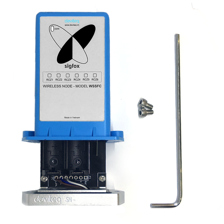
8.2 Mounting
- Installation method: Mount to the wall
-
The mounting bracket is made from hard metallic material

8.3 Battery installation

Steps for battery installation:
Step 1: Using M4 Hex key to open the cover
Step 2: Open the housing, then insert 02 x AA 1.5VDC battery, please take note the poles of the battery
ATTENTION:
REVERSED POLARITY OF BATTERIES IN 10 SECONDS CAN DAMAGE THE SENSOR CIRCUIT!!!

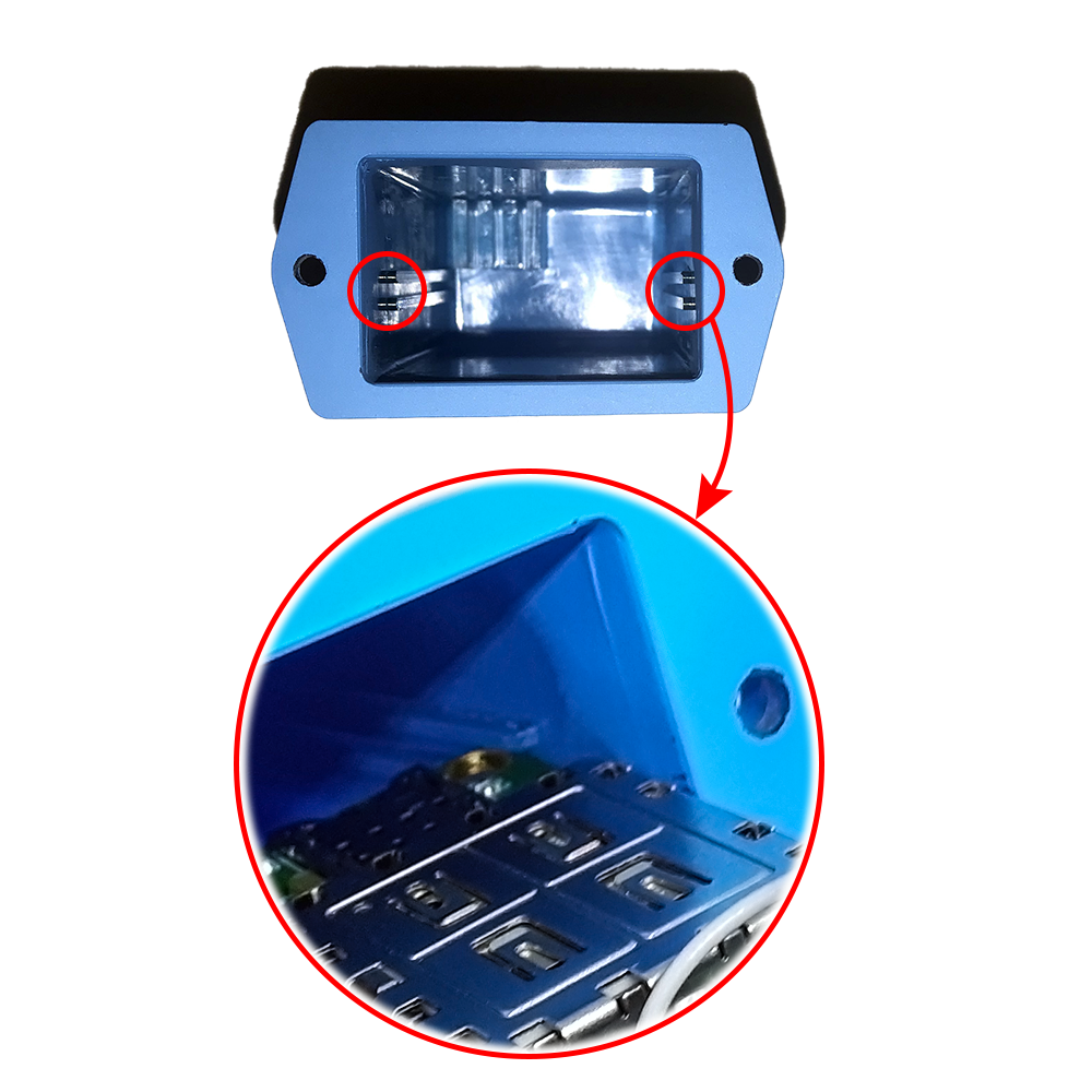
Step 3: Insert the top plastic housing (Please note the 2 reed joint)
9. Troubleshooting
| No. | Phenomena | Reason | Solutions |
| 1 | Node does not send RF to base station periodically, LED does not blink |
|
|
| 2 | Node does not send RF to base station according to the alarm, LED does not blink |
|
|
| 3 | Node does not send RF to base station when activated by the magnetic switch, LED does not blink |
|
|
| 4 | Node has blinked LED when sending RF but the base station cannot received |
|
|
| 5 | Node has sent RF but the LED does not blink |
|
|
| 6 | The measurement values from sensor do not change, keep constant values for long time |
|
|
| 7 | The node does not send RF and the RF module is hot |
|
|
| 8 | RSSI is weak and often loses data |
|
|
10. Sensor calibration
The output value of NH3 is calculated from the formula: Y= AX + B
Where:
X = measured value of NH3 from sensor and electronics circuit
Y = output value of NH3 which is sent by the Uplink
A: Constant_A at address 278 in Memmap of sensor
B: Constant_B at address 280 in Memmap of sensor
The default values are: A = 1 and B = 0 ==> Y = X
After a period of time of working the sensor output will be drifted about < 1% of the reading value per month.
So depending on what accuracy you require, you can define how long the sensor needs to be re-calibrated again.
For general application, the cycle of calibration would be 3 or 6 months. For the highest accuracy, the cycle would be 1 or 2 months.
To re-calibrate the sensor, you need to re-calculation the new values of A and B. How can it be done?
By applying the standard Zero and Span Gas. Please follow these steps:
10.1 Apply zeroing gas standard:
Before applying zeroing process, please do this step first: place the sensor in a Pure air environment from 20-25 oC in at least 1h. The sensor must be powered and running at the time.
Zeroing can be done in 1 of 2 ways as below:
- Pure air can be used as a Zero standard for NH3 calibration. Simply place the sensor in a clean environment with pure air. The ambient temperature should be from 20 to 25 oC.
- Or using high purity Nitrogen gas (99.999%) as a zero standard gas. Attach the calibration cap into the sensor and turn on the Valve to provide the N2 flow into the sensor.
Waiting for the zero gas to enter completely into the sensor for at least 15 minutes, then using the magnet key to activate the SW1. This action will force the sensor to send the new measured data to the Sigfox backend, you got the measured value Y_o.
10.2 Apply span gas standard:
As the sensor has the maximum measurement range is 100ppm, you can use any standard NH3 gas cylinder with a concentration from 25ppm to 100ppm for calibration. Please follow the steps below:
- Attach the calibration cap into the sensor and turn on the Valve of the cylinder to provide the span gas flow into the sensor.
Waiting for the span gas to enter completely into the sensor for at least 5 minutes, then using the magnet key to activate the SW1. This action will force the sensor to send the new measured data to the Sigfox backend, you got the measured value Y_s.
10.3 Calculate the new value A and B
From the existing A and B values and the measured value Y_o and Y_s and the 0ppm (zero standards) and 25ppm (for example using 25ppm NH3 standard gas), you can calculate the new value of A and B as below formula.
Ex: We have values
| Two calibration points | Standard value | The value read from Sigfox device |
| 1 | 50 | 70 |
| 2 | 1000 | 1100 |
| The old A configuration | 1 |
| The old B configuration | 0 |
We have:
A = (1000-50) / (1100-70) = 0.92233
From the formula: Y = AX + B. Then B = Y - AX = 1000 - 0.92233 x 1100 = -14.56311
| The new A configuration | 0.92233 |
| The new B configuration | -14.56311 |
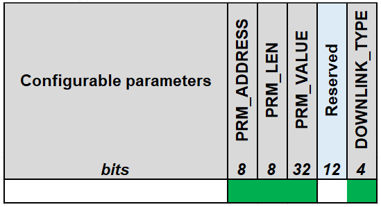
10.4 Set the new value A and B by Downlink
As the A and B values are separated values in the memmap of the sensor, we need to use 02 downlink messages to send to the sensor. Each message will send 1 value of A or B.
For example: A = 1.1 and B = 0.2. Here are the downlink message for setting A & B
| Parameter | PRM_ADDRESS | PRM_LENGTH | PRM_VALUE | DOWNLINK_TYPE | Full Downlink |
| (bytes) | 1 | 1 | 4 | 2 | 8 |
| CONSTANT_A | 0x16 | 0x04 = 4 | 0x3F8CCCCD = 1.1 | 0x0005 | 16043F8CCCCD0005 |
| CONSTANT_B | 0x18 | 0x04 = 4 | 0x3E4CCCCD = 0.2 | 0x0005 | 18043E4CCCCD0005 |
| HIGH_CUT | 0x1A | 0x04 = 4 | 0x447A0000 = 1000 | 0x0005 | 1A04447A00000005 |
| LOW_CUT | 0x1C | 0x04 = 4 | 0x00000000 = 0 | 0x0005 | 1C04000000000005 |
| SENSOR_BOOT_TIME | 0x1E | 0x04 = 4 | 0x000000C8 = 200 | 0x0005 | 1E04000000C80005 |
| SYSTEM_SENSITIVITY | 0x32 | 0x04 = 4 | 0x41300000 = 11 | 0x0005 | 3204413000000005 |
11. Sensor module replacement:
11.1 Remove old sensor module:
- Carefully remove the filter;
- Remove the exiting sensor module by using your finger to grip and pull it out;
11.2 Install new sensor module:
- Unbox the new sensor in the box;
- Carefully remove the spring between the 02 pins of the sensor, as below picture;
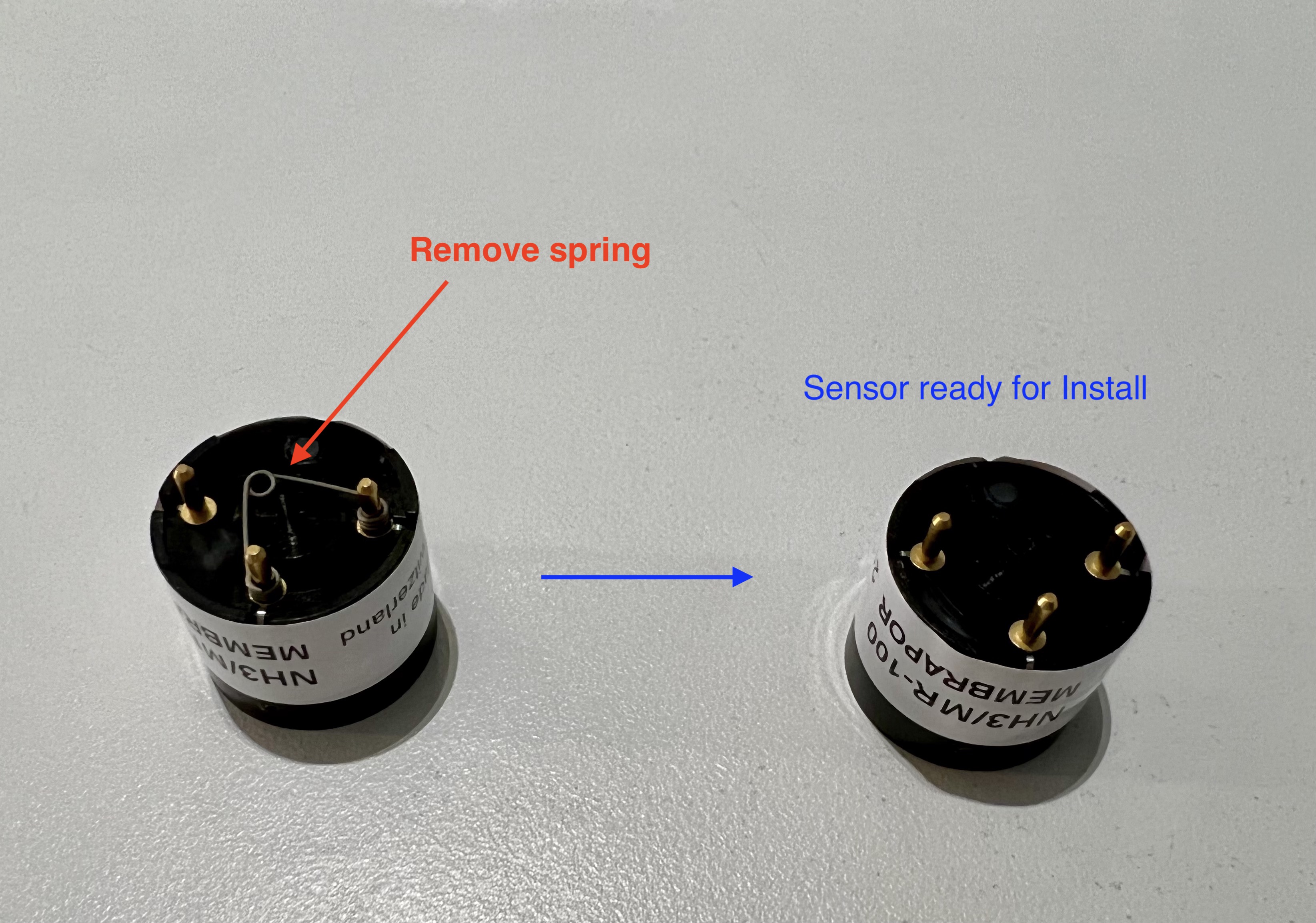
- Plug the sensor module into the device. Make sure the 03 pins of the sensor are completely inserted inside the sockets. Please see the below picture.
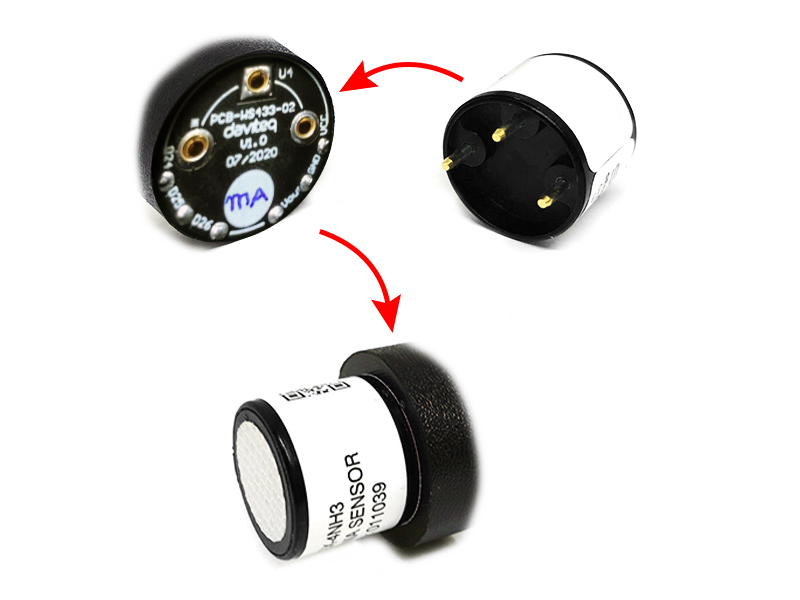
- Place the filter again and tighten it.
12. Support contacts
|
Manufacturer
Daviteq Technologies Inc Email: info@daviteq.com | www.daviteq.com
|
|
|
No Comments