Manual of STHC-ISGWET-WS433-CL-04 | FW8
I. QUICK GUIDE
1. Introduction
1.1 Introduction
STHC-WET is a Smart IoT Gateway, aka iConnector, a main component in any IoT application. iConnector has a role to connect the real World's things like sensors, meters, machines...to server system for data logging, data analytics, monitoring & controls...iConnector support multiple Industrial Fieldbus like Modbus RTU, Ethernet IP, Wireless sensor network...It connects to server system via LAN/WAN as Ethernet, WiFi.
1.2 System architecture
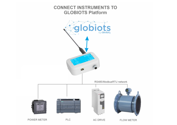
1.2.1. Connect instruments to GLOBIOTS Platform
1.2.2. Connect wireless sensor to GLOBIOTS Platform
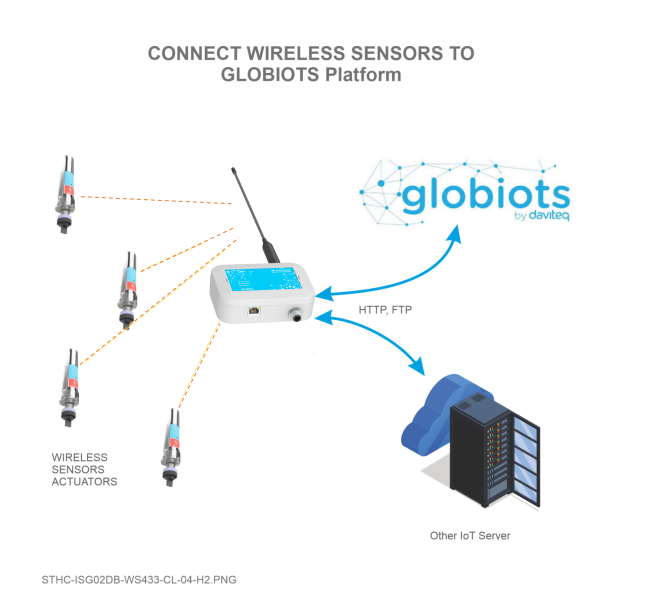
1.2.2. Connect wireless sensor to any PLC or HMI/SCADA

2. Application note
- Typical Application: Energy management, environment monitoring, smart building, smart factory,...
- Multi-Protocol Support: Modbus RTU/TCP, EthernetIP, Sub-GHz
- Flexible Connectivity: Ethernet, WiFi
- Features: Automatically collect parameters and energy data; Unified and centralized management of all energy types in a single system; Many prominent features, such as users grouping and management, data visualization, and automatic reporting; Flexible investment options and easy system expansion.
3. iConnector communication
3.1. Slave device communication
3.1.1. Modbus RTU Master
In this function, iConnector work as a Modbus RTU Master. It can poll for data from and write data to external Modbus Slaves connected to it through RS485 physical protocol.
3.1.2. Wireless co-ordinator
Thanks to the wireless co-ordinator has been integrated in the iConnector, it is able to connect with any Daviteq Sub-GHz devices. By the Sub-Ghz technology from Texas Instruments, it is easy to establish multiple networks in same area without interference or channel conflict. One co-ordinator can handle maximum of 40 end nodes in its network. Prefer the link below to reach more detail information of this function
Long Range Wireless Co-ordinator WS433-CL manual
3.2 Host communication
The iConnector are designed to connect to Daviteq Platform, aka Vizuo Globiots. Vizuo Globiots is a web-based software application to remotely configure device, parameter, alarm and event. In addition, Vizuo displays current values, historical values of parameters as well as events, alarms. Values of parameter are stored on database of GLOBIOTS server.
In additional, iConnector is able to send data to any servers via common protocols such as HTTP, FTP, UDP/IP,...
Refer Section 10. How to connect device to Back-end/ Server to see more detail instruction.
4. Default Configuration
4.1. UDP Server
The iConnection was configured to connect to Daviteq's platform
| Parameters | Default value |
| UDP_SERVER_HOST | dataengine.globiots.com |
| UDP_SERVER_PORT | 9000 |
| DRM_TIMEOUT (sec) | 20 |
| TIME_ZONE | 7 |
4.2. Main network
In default mode, the iConnector connects to server through WIFI. Refer section 7.1 to see how to change the network mode.
4.3. Wireless co-ordinator
| Parameters | Default value |
| Modbus address | 1 |
| Modbus baudrate | 9600 bps |
| Modbus parity | none |
| Radio frequency | 433.92 MHz |
| Tx power | 15 dBm |
| Data rate RF | 50 kbps |
5. Battery/ Power Supply
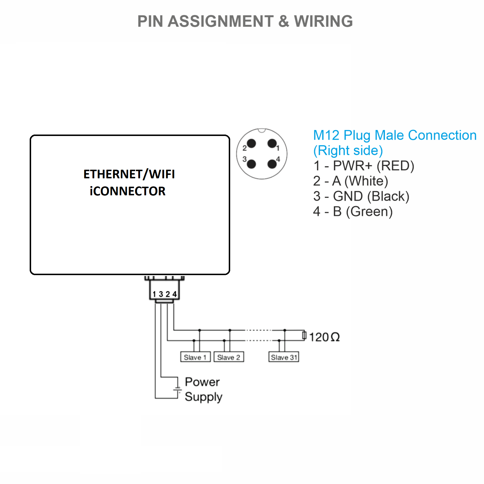
iConnectors are powered via M12 Male connector. The power supply range is 7..48VDC, avg 200mA, peak 1.5A
Detail wiring instruction, please refer section 8. Installation and wiring.
6. What's in the Package?
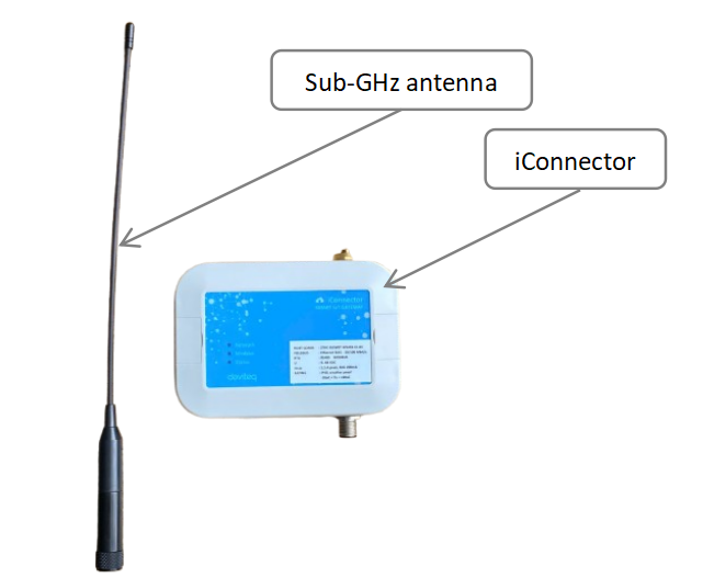
The packages include:
01 x iConnector
01 x Sub-GHz antenna
7. Guide for Quick Test
7.1. Connecting the iConnector to the Daviteq Platform
Refer section 3.2.2 Offline configuration to see how to use the iConfig software
Step 1: Configure the iConnector via iConfig software
- Get basic information of the iConnector to register it into Daviteq Platform including Serial number & FCC
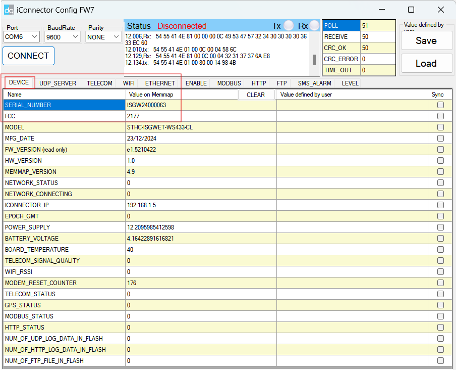
- Setup network information in order that the iConnector can go online in the internet. Base on your application, you should configure wifi or ethernet information.
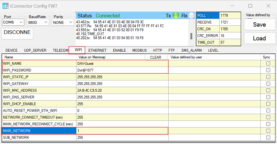
WIFI mode
In this mode, there are three parameters must be configured, including MAIN_NETWORK , WIFI_NAME, WIFI_PASSWORD
| Parameters | Description |
| MAIN_NETWORK | 1: WIFI mode 2: ETHERNET mode |
| WIFI_NAME | Wifi name of WIFI network |
| WIFI_PASSWORD | Password of WIFI network |
ETHERNET mode
In this mode, there are five parameters should be configured, including MAIN_NETWORK , ETHERNET_STATIC_IP, ETHERNET_GATEWAY, ETHERNET_DNS_SERVER, ETHERNET_DHCP_ENABLE
| Parameters | Description |
| MAIN_NETWORK | 1: WIFI mode 2: ETHERNET mode |
| ETHERNET_STATIC_IP | The static IP of Ethernet network use for iConnector. If running DHCP mode, ignore this parameter |
| ETHERNET_GATEWAY | The default gateway of Ethernet network use for iConnector. If running DHCP mode, ignore this parameter |
| ETHERNET_DNS_SERVER | The DNS server of Ethernet network use for iConnector. |
| ETHERNET_DHCP_ENABLE | 0 = DISABLE, 1 = ENABLE |
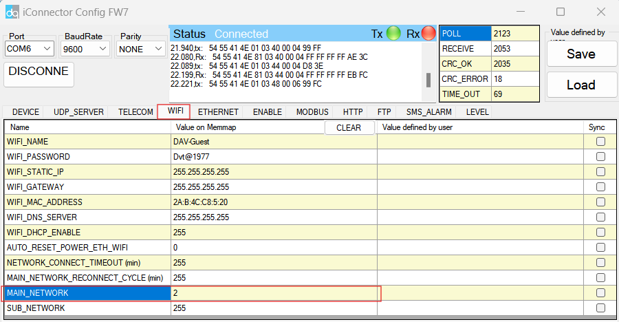
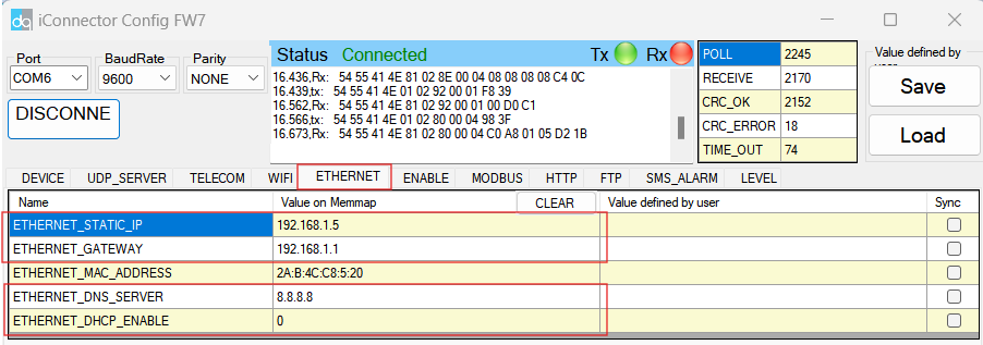
The parameter MAIN_NETWORK is located in the WIFI tab of the software, while other parameters are in the ETHERNET tab.
Step 2: Read data of iConnector from Daviteq Platform
- Access to Vizuo Globiots via the link https://vizuo.globiots.com and login to the system with the username and password supplied Daviteq.

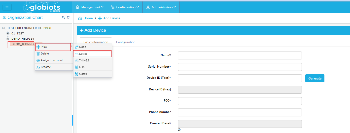
- Register the iConnector into Globiots
- RIGHT-CLICK on the corresponding site in the Organization Chart => New=>Device
-
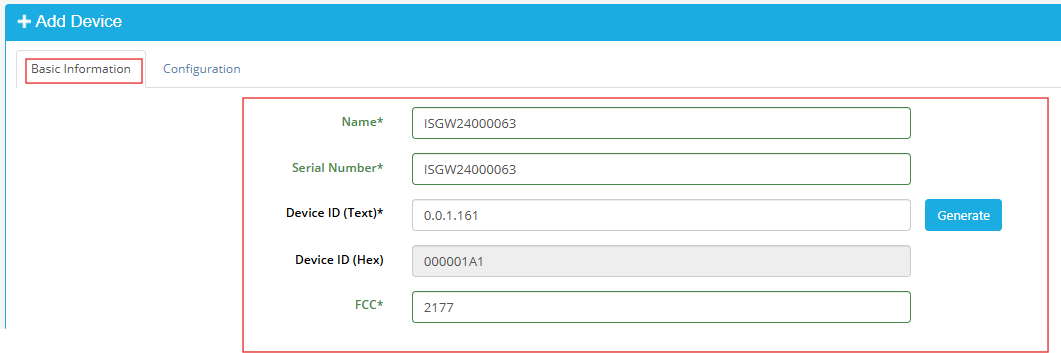
- There are some fields must be configured, including Name, Serial number, Device ID, FCC, Memmap, Logging send frequency, Health send frequency. After the fields were configured => Click Save button
Fields Description Name Optional name, must be 12 characters Serial number Serial number of iConnector
*Taken from step 1Device ID Click Generate button in the software FCC FCC of iConnector
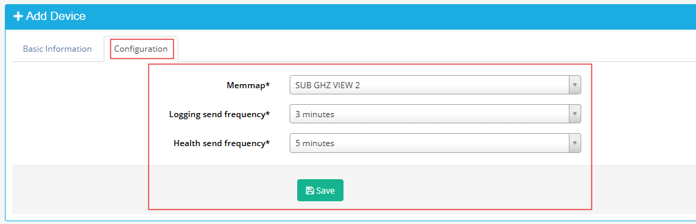
*Taken from step 1Memmap Choose SUB-GHZ VIEW 2 Logging send frequency Choose 3 minutes Health send frequency Choose 5 minutes
- There are some fields must be configured, including Name, Serial number, Device ID, FCC, Memmap, Logging send frequency, Health send frequency. After the fields were configured => Click Save button
- Add parameter to read data from the iConnector
- Download the parameter file in link
- Right-click on the device=>Pararameter
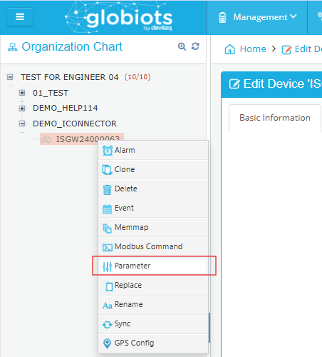
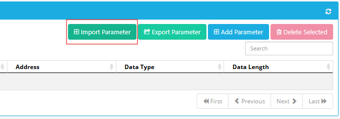
-
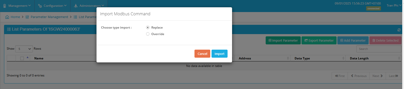
- Choose the parameter file=> Tick Replace option=> Click Import button
Refer the link below to see more detail of parameter configuration
https://daviteq.com/en/manuals/books/user-guides-for-vizuo-software-on-web/page/vizuo-software-on-web#bkmrk-5.4-configure-parame
- Add basic dashboard to show data of the iConnector
- Download the dashboard file in the link
- In Home screen, select Management => select sub-menu Dashboard
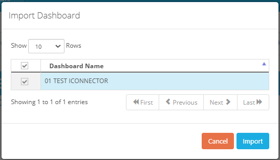
- Click Stop button=> Click Import button
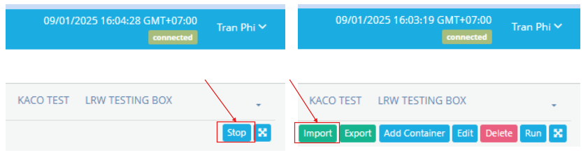
-
- Choose the Dashboard file=> Tick 01 TEST ICONNECTOR => Click Import button
-

7.2. Read data of Wireless sensors from Globiots
Make sure the process in section 7.1 was completed successfully.
Step 1: Add Sub-GHz sensor to the iConnector
Refer Section 5.1 Add sensors node to Co-ordinator WS433-CL in the link
Step 2: Read data from Daviteq Platform
Refer section 5. Configure Device of the Globiots manual in the link to get the instruction of configurating the iConnector in Globiots
7.3. Read data of Modbus slave from Globiots
Make sure the process in section 7.1 was completed successfully.
Step 1: Establish the RS485 network among iConnector and modbus slaves
Step 2 : Get modbus information of slave devices
Step 3: Read data from Daviteq Platform
Refer section 5. Configure Device of the Globiots manual in the link to get the instruction of configurating the iConnector in Globiots
7.4. Modbus TCP/IP converter function
Principle Flow of this function as below
- iConnector is connected to the Modbus RTU slave as with electric meters, devices, ... via RS485 port;
- Software / device / PLC ... with Modbus TCP Client connected to iConnector (role as TCP Server)
- TCP Client sends command to iConnector;
- iConnector transfers commands from Modbus TCP to RTU and sends to devices via RS485 port;
- iConnector waits for the devices to respond;
- iConnector transfers the response from the RTU to the Modbus TCP and then sends it back to the TCP Client;
- TCP Client actively closes the connection if it no longer sends command to iConnector.
Step 1: Configure the iConnector via iConfig software
Refer section x.xx to see how to use the iConfig software
- Configure the iConnector at Ethernet tab
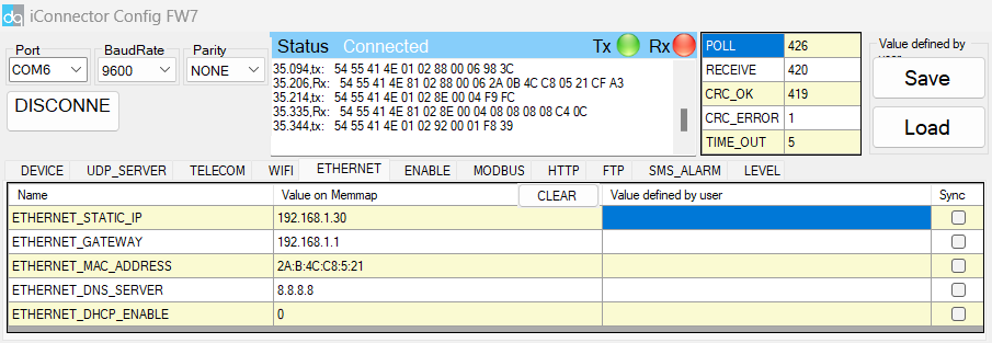
| Name | Description |
| IP | Static IP configuration for iConnector. Example: 192.168.1.30 |
| Gateway | Configure gateway |
| DNS Server | Configure DNS Server |
| DHCP |
Configure to 0, it's mean Not using DHCP → Static IP |
- Configure the iConnector at Modbus tab
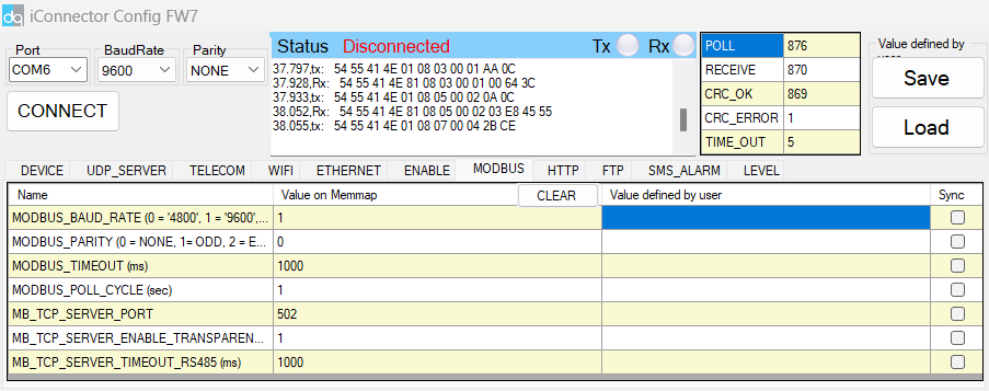
| Name | Description |
| MODBUS_BAUD_RATE | Configure the modbus baudrate to 9600 bps |
| MODBUS_PARITY | Configure the parity to none |
| MODBUS_TIMEOUT | Configure the modbus timeout to 1000 ms |
| MODBUS_POLL_CYCLE | Configure the modbus poll cycle to 1s |
| MB_TCP_SERVER_PORT | Configure the receiving port to 502 |
| MB_TCP_SERVER_ENABLE_TRANSPARENT |
Configure to 1 : To run transparent, interrupt modbus RTU poll. |
| MODBUS_TCP_SERVER_TIMEOUT | Used for modbus TCP Server |
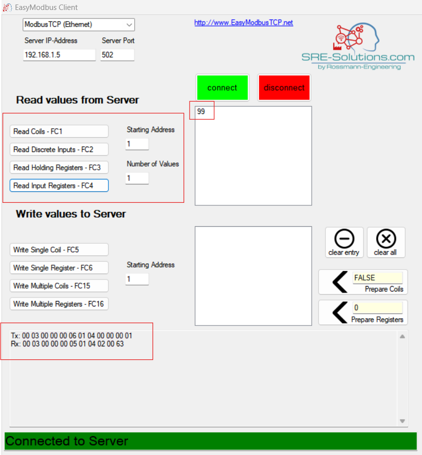
Step 2: Read data of iConnector from TCP/IP Client software
In this guide, we use Easy Modbus Client software. You can use any other Modbus TCP/IP client software
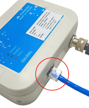
- Connect the iConnector to the PC via LAN cable.
- Connect the Modbus RTU slave to the iConnector via RS485 cable.
- Power on the devices
- In TCP/IP Client software, input correct Server IP Adresss and Port that configured in step 1. Then, click Connect button. If the status at the bottom show "Connected to server", it means the successful connection.
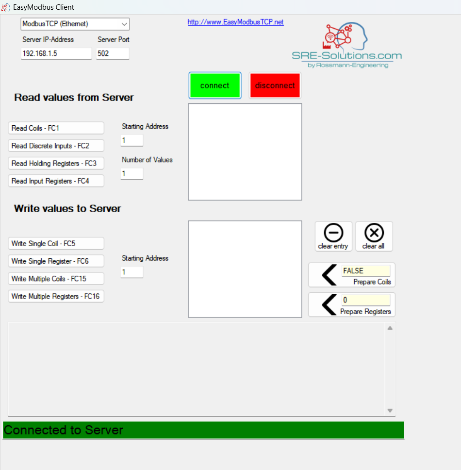
Ensure that the IP address of the PC is configured within the same subnet as the TCP/IP server address set on the iConnector in Step 1.
- Read a parameter base on the modbus memory map of slave device. For example, read a register 30001 of the Modbus slave

8. Installation and wiring
8.1.Installation and wiring for iConnector
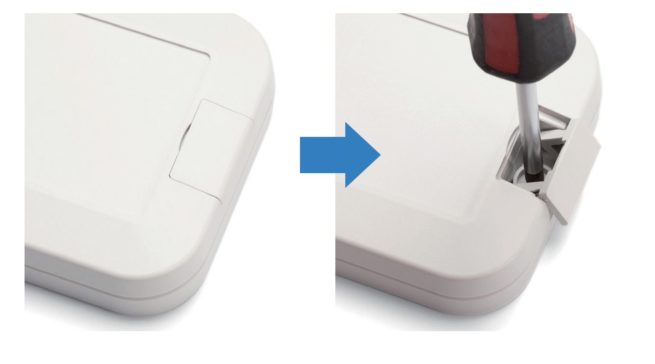
There are 02 holes for screwing at the left and right of housing.
These holes are covered by the cover.
Open the cover, you can access the hole for screwing.
Using screw with size 4mm diameter maximum.
Power the iConnector on via M12 Port. Pin 1 is PWR+ , Pin 3 is GND.
8.2 Installation and wiring for wired slave device
Connect the Modbus RTU slaves to the iConnector via RS485 protocol. Pin 2 is RS485+ (A), Pin 4 is RS485- (B)
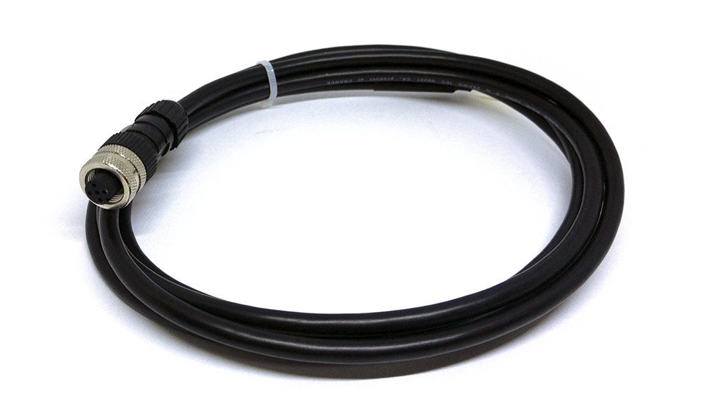
Use M12 female connection cable to connect to iConnector

8.3 Installation and wiring for wireless sensor
DO NOT install the Wireless sensor or its antenna inside a completed metallic box or housing, because the RF signal can not pass through the metallic wall. The housing is made from Non-metallic materials like plastic, glass, wood, leather, concrete, cement…is acceptable.
8.4 Installation and wiring for host Modbus TCP/IP
Connect the iConnector with TCP/IP client via the LAN cable.
9. Payload Document and Configuration Tables
Download the iConnector Modbus Memory Map in the link
10. How to connect device to Back-end/ Server
10.1 How to connect device to Globiots platform
Read the section 7.1 Connecting the iConnector to the Daviteq Platform to get the instruction of adding the iConnector to the Globiots platform.
10.2 How to connect device to http server
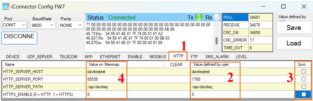
Step 1: Connect the iConnector to a PC via Modbus configuration cable, then open the iConfig software. After that, set up correct port, baud rate, parity and click Connect button
Step 2: Choose HTTP tab, fill in the information of HTTP sever, such as HTTP_SERVER_HOST, HTTP_SERVER_PORT, HTTP_SERVER_PATH, HTTPS_ENABLE (0 = HTTP, 1 = HTTPS) in Value defined by user column. Then, tick in the corresponding cell of these configuration in Sync column. After that, check the value in the Value on memmap column.
II. MAINTENANCE
2.1 Maintenance
There is no requirement for maintenance of the Hardware of the iConnnector
2.2 Troubleshooting
| No. | Phenomena | Reason | Solutions |
| 1 | Cannot read modbus |
|
|
| 2 |
Failed to add auto sensor (iConnector integrated Co-ordinator version) |
|
|
| 3 | Read modbus normal health values but read the data of the node, all are 0 |
|
|
| 4 | The node's data has no data of prm1 and prm2 |
|
|
| 5 | Status led of iConnector doesn’t light |
|
|
| 6 | Mobus led of iConnector doesn’t light |
|
|
| 7 | Network led of iConnector doesn’t light |
|
|
III. ADVANCE GUIDE
3.1 Principle of Operation
3.1.1 LED meaning
3.1.1.1 LED status
| Status | Meaning |
| Fixed ON | iConnector has been supplied with external power |
| Blinking (4 seconds blink 1 time) | Without external power, iConnector is using battery. |
| Blinking (2 seconds blink 1 time) | Low battery warning (Used for type D battery version) |
3.1.1.2 LED modbus
| Status | Meaning |
| Fixed ON | Modbus connected |
| Blinking (1 seconds blink 2 time) | Connection errors (wrong configuration of baudrate, noise, …) |
| OFF | No modbus connection |
3.1.1.3 LED network
| Status | Meaning |
| Blinking (1s change state) | Connecting with Globiots |
| Blinking (2s change state) | Initializing wifi generator, waiting for configuration via phone or modbus tool (For iConnector wifi) |
| OFF/Blinking (2s change state) | No connection with Globiots |
3.1.2 Memory Map
|
Address |
Size (bytes) |
Memory type |
Read/Write |
Description |
|
0-0x1FFF |
8096 |
FLASH |
R/W |
Save active configuration, do not allow log, realtime. |
|
0x2000-0x22FF |
768 |
RAM |
R |
Save data read from modbus slaves. |
|
0x2300-0x24FF |
512 |
RAM |
R |
The intrinsic data of iConnector |
|
0x3000-0x30FF |
256 |
RAM |
R/W |
|
|
0x5000-0x50FF |
256 |
FLASH |
R/W |
|
|
0x6000-0x6FFF |
4096 |
RAM |
R |
Save data read from modbus slaves |
- Data address area: 0x2000-0x22FF (768 bytes), and 0x6000-0x6FFF (4096 bytes).
- Controller address area: 0x3000-0x30FF (256 bytes, without flash storage), and 0x5000-0x50FF (256 bytes, with flash storage).
Address area 0x5000-0x50FF
- 256 bytes;
- Save in flash (when power is lost, will keep the same value);
- Allows reading, and writing from Globiots;
- Allow log (realtime);
- Allows Modbus write to Slaves;
- It is not allowed to store data read from Modbus Slaves.
NOTE: Flash recorded about 100,000 times will be damaged so do not use this area to contain the value is changed several times.
3.1.3 Logged data
- Up to 20 different log cycles;
- 320 log parameters maximum for all log cycles.
- Up to 120 log parameters per log cycle.
3.1.4 Modbus
- Support modbus RTU.
- Address slave 1… 247.
- It is not allowed to set address slave = 0.
- Baudrate 4800/9600/19200.
- Parity none / odd / even.
- Up to 100 modbus instructions.
- The address area for storing read data: 0x2000-0x22FF (768 bytes), and 0x6000-0x6FFF (4096 bytes).
- Controller address area: 0x3000-0x30FF (256 bytes, without flash storage), and 0x5000-0x50FF (256 bytes, with flash storage).
3.1.5 Realtime
- Read up to 200 parameters.
- If all parameters are float (4 bytes) then read up to 140 parameters.
- The fastest realtime sending frequency is 1 second.
- Up to 28 alarms.
- Supported data types:
|
PrmType |
Description |
# Byte |
Range |
|
1 |
BYTE |
1 |
0 to 255 |
|
2 |
UINT16 |
2 |
0 to 65,535 |
|
3 |
UINT32 |
4 |
0 to 4,294,967,295 |
|
4 |
FLOAT |
4 |
-/+3.40282347 * (10^+38) |
|
5 |
INT16 |
2 |
-32,768 to 32,767 |
|
6 |
INT32 |
4 |
-2,147,483,648 to 2,147,483,647 |
3.1.7 Event
- The event table is 1024 bytes.
- The number of events depends on the short length of the event configured.
- Supported data types:
|
PrmType |
Description |
# Byte |
Range |
|
1 |
BYTE |
1 |
0 to 255 |
|
2 |
UINT16 |
2 |
0 to 65,535 |
|
3 |
UINT32 |
4 |
0 to 4,294,967,295 |
|
4 |
FLOAT |
4 |
-/+3.40282347 * (10^+38) |
|
5 |
INT16 |
2 |
-32,768 to 32,767 |
|
6 |
INT32 |
4 |
-2,147,483,648 to 2,147,483,647 |
3.1.8 Health data
- Every 15 seconds send health pack 1 time.
3.2 Configuration
3.2.1 Online configuration from Globiots
Refer section 5. Configure Device of the Globiots manual in the link to get the instruction of configurating the iConnector in Globiots
3.2.2 Offline configuration
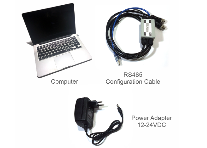
Step 1: Preparation
Prepare some required devices as below
01x A window PC
01x USB-RS485 Configuration Cable
01x Power adapter 12-24VDC
Download the Configuation software in the link
Step 2: Hardware connection
- Connect the USB-A to the PC
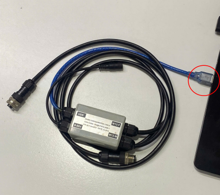
- Connect M12 female of the cable to the iConnector

- Power the iConnector on by connecting DC jack from Power Adapter
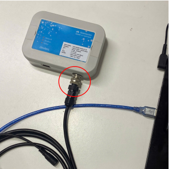
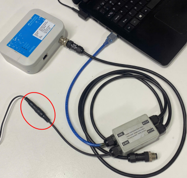
The above steps must be performed in order
Step 3: Configuration the iConnector via iConfig software
- Open the iConfig software, then choose Correct Port, BaudRate and Parity.
Port is based on the PC
BaudRate is 9600
Parity is NONE
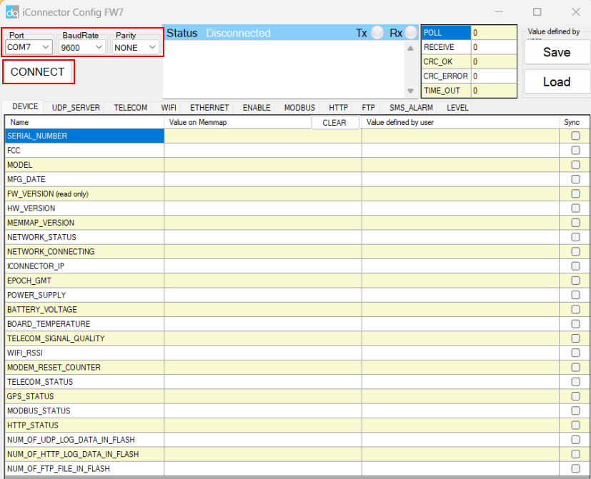

(1) There are 11 configuration tabs on the top banner. Click a tab name to navigate to the corresponding sheet.
(2) The first column displays the parameter names of the iConnector.
(3) The second column shows the current values of the corresponding parameters
(4) The third column is where users can input new configuration values.
(5) After entering the new configuration in the third column, users must tick the corresponding checkbox to apply it. The tick will disappear once the new configuration is successfully written to the iConnector. After that, the updated value will appear in the second column.
IV.PRODUCT SPECIFICATIONS
4.1 Specifications
| Host Communication Ethernet type | 01 x RJ45 port, 10Mbps |
| Host Communication WiFi type | 802.11b/g/n, 2.4Ghz,internal antenna |
| Host communication supports | TCP/IP, UDP/IP, FTP, HTTPS, SNMP... |
| Fieldbus communication | Modbus RTU x 01 port, 31 slaves, max 19.2 kpbs |
| Optional | Integrated wireless co-ordinator with external antenna or internal antenna |
| Power supply | 7..48VDC, avg 200mA, peak 1.5A |
| On-board memory & sensors | 2MB Flash, PCB temperature sensor |
| Electrical connectors | M12, 4-pin, coding A or 9mm Power Plug and USB port |
| Included accessories | mounting bracket for wall mount (cellular version only) |
| Operating Temperature/Humidity | -20 .. + 60 degC / 95%RH, non-condensing |
| Housing/Protection | Anti-UV plastic for Ethernet/WiFi version. All version is IP67 protection |
| Dimension | H130xW90xD40 for Ethernet/WiFi versions |
| Net weight | 190 grams for Cellular version, 350 grams Ethernet/WiFi versions |
V. WARRANTY & SUPPORT
5.1 Warranty
Below terms and conditions are applied for products manufactured and supplied by Daviteq Technologies Inc.
Free Warranty Conditions
-
The manufacturer undertakes to guarantee within 12 months from shipment date.
-
Product failed due to defects in material or workmanship.
-
Serial number, label, warranty stamp remains intact (not purged, detected, edited, scraped, tore, blurry, spotty, or pasted on top by certain items).
-
During the warranty period, if any problem of damage occurs due to technical manufacturing, please notify our Support Center for free warranty consultancy. Unauthorized treatments and modifications are not allowed.
-
Product failed due to the defects from the manufacturer, depending on the actual situation, Daviteq will consider replacement or repairs.
Note: One way shipping cost to the Return center shall be paid by Customers.
Paid Warranty
-
The warranty period has expired.
-
The product is not manufactured by Daviteq.
-
Product failed due to damage caused by disasters such as fire, flood, lightning or explosion, etc.
-
Product damaged during shipment.
-
Product damaged due to faulty installation, usage, or power supply.
-
Product damage caused by the customer.
-
Product rusted, stained by effects of the environment or due to vandalism, liquid (acids, chemicals, etc.)
-
Product damage is caused by unauthorized treatments and modifications.
Note: Customers will be subjected to all repairing expenses and 2-way shipping costs. If arises disagreement with the company's determining faults, both parties will have a third party inspection appraise such damage and its decision be and is the final decision.
5.2 Support
Support via Help center
For support, please contact our support center at the following link: https://support.daviteq.com/hc/en-us
-
If you have any questions about the product, you can search for information on that page;
-
If you can't find the right information, please register an account and send us a request. We will respond within 24 hours;
-
Our support engineer will contact you via the Ticket system. If the product needs to be sent back to the factory for warranty, we will generate an RMA code so you can send it back to us. To follow the status of the RMA process, customers can visit our SupportSync system as below.