QUICK GUIDE
1. Introduction
1.1 Introduction
STHC is a Smart IoT Gateway, aka iConnector, a main component in any IoT application. iConnector has a role to connect the real World's things like sensors, meters, machines...to server system for data logging, data analytics, monitoring & controls...iConnector support multiple Industrial Fieldbus like Modbus RTU, EthernetIP, Wireless sensor network...It connects to server system via LAN/WAN as Ethernet, WiFi or Cellular.
1.2 System architecture
1.3 System components
2. Application note
3. iConnector communication
3.1 Slave device communication
3.1.1. Modbus RTU Master
In this function, iConnector work as a Modbus Master. It can poll for data from and write data to external Modbus Slaves connected to it through RS485 physical protocol.
3.1.2. Wireless co-ordinator
Thanks to the wireless co-ordinator has been integrated in the iConnector, it is able to connect with any Daviteq Sub-GHz devices. By the Sub-Ghz technology from Texas Instruments, it is easy to establish multiple networks in same area without interference or channel conflict. One co-ordinator can handle maximum of 40 end nodes in its network. Prefer the link below to reach more detail information of this function
Long Range Wireless Co-ordinator WS433-CL manual
3.2 Host communication
The iConnector are designed to connect to Daviteq Platform, aka Vizuo Globiots. Vizuo Globiots is a web-based software application to remotely configure device, parameter, alarm and event. In addition, Vizuo displays current values, historical values of parameters as well as events, alarms. Values of parameter are stored on database of GLOBIOTS server.
In additional, iConnector is able to send data to any servers via common protocols such as HTTP, FTP, UDP/IP,...
Refer Section 10. How to connect device to Back-end/ Server to see more detail instruction.
4. Default Configuration
4.1. UDP Server
The iConnection was configured to connect to Daviteq's platform
| Parameters | Default value |
| UDP_SERVER_HOST | dataengine.globiots.com |
| UDP_SERVER_PORT | 9000 |
| DRM_TIMEOUT (sec) | 20 |
| TIME_ZONE | 7 |
4.2. Main network
In default mode, the iConnector connects to server through WIFI. Refer section xx.xx to see how to change the network mode.
5. Battery/ Power Supply
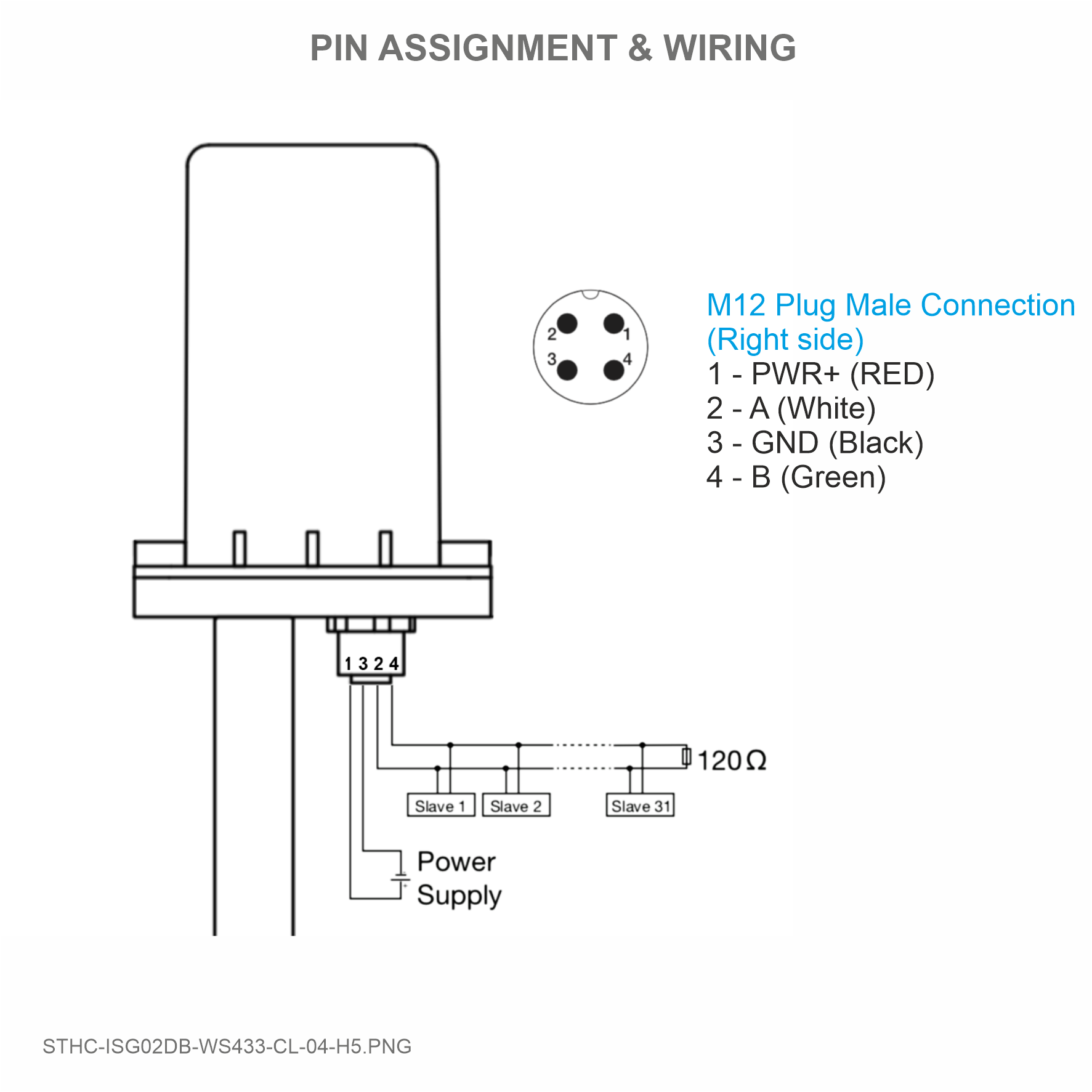
iConnectors are powered via M12 Male connector. The power supply range is 7..48VDC, avg 200mA, peak 1.5A
Detail wiring instruction, please refer section 8. Installation and wiring.
6. What's in the Package?
7. Guide for Quick Test
7.1. Connecting the iConnector to the Daviteq Platform
Step 1: Configure the iConnector via iConfig software
- Get basic information
- Setup network information
Step 2: Read data of iConnector from Daviteq Platform
- Login to Vizuo Globiots
- Add device
- Add parameter (power supply)
- Add basic dashboard to show data
7.2. Read data of Wireless sensors from Globiots
Make sure the process in section 7.1 was completed successfully.
Step 1: Add Sub-GHz sensor to the iConnector
- Open software=> import template
- Install the batteries to the wireless sensor, then touch the sensor to the iConnector'antenna. If the iConnector sound "beep", it mean the paring process is successful.
Step 2: Read data from Daviteq Platform
- Create the parameter
- Create the modbus command
- Add the basic dashboard to show data
7.3. Read data of Modbus slave from Globiots
Make sure the process in section 7.1 was completed successfully.
Step 1: Establish the RS485 network among iConnector and modbus slaves
- wiring
- get modbus information of slave devices
Step 2: Read data from Daviteq Platform
- Create the parameter
- Create the modbus command
- Add the basic dashboard to show data
7.4. Modbus TCP/IP converter function
Step 1: Configure the iConnector via iConfig software
Refer section x.xx to see how to use the iConfig software
- Configure the iConnector at Ethernet tab
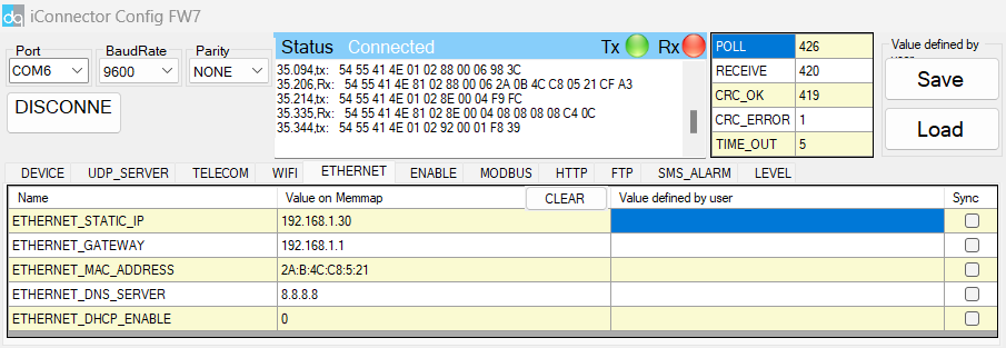
| Name | Description |
| IP | Static IP configuration for iConnector. Example: 192.168.1.30 |
| Gateway | Configure gateway |
| DNS Server | Configure DNS Server |
| DHCP |
Configure to 0, it's mean Not using DHCP → Static IP |
- Configure the iConnector at Modbus tab
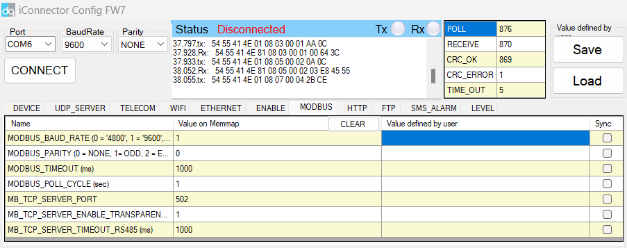
| Name | Description |
| MODBUS_BAUD_RATE | Configure the modbus baudrate to 9600 bps |
| MODBUS_PARITY | Configure the parity to none |
| MODBUS_TIMEOUT | Configure the modbus timeout to 1000 ms |
| MODBUS_POLL_CYCLE | Configure the modbus poll cycle to 1s |
| MB_TCP_SERVER_PORT | Configure the receiving port to 502 |
| MB_TCP_SERVER_ENABLE_TRANSPARENT |
Configure to 1 : To run transparent, interrupt modbus RTU poll. |
| MODBUS_TCP_SERVER_TIMEOUT | Used for modbus TCP Server |
Step 2: Read data of iConnector from TCP/IP Client software
8 Installation and wiring
8.1.Installation and wiring for iConnector
8.2 Installation and wiring for wired slave device
8.3 Installation and wiring for wireless sensor
8.4 Installation and wiring for host Modbus TCP/IP
Connect the iConnector with TCP/IP client via the LAN cable.