Payload for LoRaWAN Sensors
- Payload for LoRaWAN Lidar People Counter WSLRW-LPC
- Payload for LoRaWAN Flammable Gas Sensor WSLRWEX-GHC or WSLRW-GHC
- Payload for LoRaWAN Gas Sensor WSLRW-G4 or WSLRWEX-G
- Payload for LoRaWAN Tilt Sensor WSLRW-AG
Payload for LoRaWAN Lidar People Counter WSLRW-LPC
Payload WSLRW-LPC | Firmware 1.0
1. Payload document is applied for the following products
| Item code | HW Version | Firmware Version | Remarks |
| WSLRW-LPC-11 | 1.0 | 1.0 | |
2. Changes information in this version v.s previous version
| Item | Changes | Changed by | Changed Date | Approved by | Approved Date |
| 1 | Initial version | P.N.Diep | 09-05-2022 | N.V.Loc | 28-05-2022 |
The approved date is also the release date of this document.
3. Payload for Uplink messages
| When? | Purpose | Wait for Downlink? | LED color |
| This message will be sent in the pre-defined cycle OR when the resettable counter passes the threshold | To get the measured value from the device in the pre-defined cycle or when the counter passes the threshold | NO |
Not applicable |
Uplink Payload structure:
|
Payload |
Sensor type |
Battery level |
Hw_error |
reserved |
NRC_People_in |
NRC_People_out |
RC_People_in |
RC_People_out |
Dist_front_zone |
Dist_back_zone |
|
bits |
8 |
2 |
2 |
4 |
16 |
16 |
8 |
8 |
16 |
16 |
|
Value |
yes |
yes |
yes |
zeros |
yes |
yes |
yes |
yes |
yes |
yes |
4. Payload Fields of Uplink
The length of the uplink payload is 12 bytes. Please refer below for an explanation.
|
Data |
Size (byte) |
Bit |
Format |
Meaning |
|
Sensor type |
1 |
all |
Uint8 |
Sensor type = 0x13 means LoRaWAN People Counter |
|
Status: battery level |
1 |
Bit 7 and 6 |
Uint8 |
Battery capacity in 04 levels |
|
|
|
|
|
11: battery level 4 (99%) |
|
|
|
|
|
10: battery level 3 (60%) |
|
|
|
|
|
01: battery level 2 (30%) |
|
|
|
|
|
00: battery level 1 (10%) |
|
Status: sensor module error |
|
Bit 5 and 4 |
|
Status |
|
|
|
|
|
01: sensor module error |
|
|
|
|
|
00: no error with sensor module |
|
NRC_People_in |
2 |
all |
Uint16 |
Non-resettable counter |
|
NRC_People_out |
2 |
all |
Uint16 |
Non-resettable counter |
|
RC_People_in |
1 |
all |
Uint8 |
Reset to 0 after sending to Gateway |
|
RC_People_out |
1 |
all |
Uint8 |
Reset to 0 after sending to Gateway |
|
Dist_front_zone |
2 |
all |
Uint16 |
Distance of front zone |
|
Dist_back_zone |
2 |
all |
Uint16 |
Distance of back zone |
5. Payload for Downlink messages
Users can use a downlink message to change the configuration of the device. There are 02 types of downlink messages:
- Downlink type = 0: to write the configuration for the specific type of Sigfox-ready sensor. The format is fixed for each type of sensor. However, this FW version does not support type 0 configuration. It only supports type 5 as below.
- Downlink type = 5: to write a value to any address of configuration parameter of any Sigfox-ready sensor. This method is generic and can be applied to any type of Sigfox-ready sensor, the user just needs to know the memory map of the sensor.
5.1 Downlink type = 0
Not available in this FW version.
5.2 Downlink type = 5
With this downlink, the user can write the configuration to any address on the memory map of the device. Please refer to the memory map of the device to understand what parameters can be written.
The length of the configuration parameter can be 1, 2 bytes, or 4 bytes, but the total length of the Downlink payload must equal 64 bits (8 bytes). Please see below the downlink format for both types.
Downlink type 5 for the parameter of 2 bytes length:
|
Payload |
PRM_ADDRESS |
PRM_LENGTH |
PRM_VALUE |
reserved |
DOWNLINK_TYPE |
|
bits |
8 |
8 |
16 |
28 |
4 |
|
Value |
yes |
0x02 = 2 |
yes |
zeros |
0b0101 = 5 |
Downlink type 5 for the parameter of 4 bytes length:
|
Payload |
PRM_ADDRESS |
PRM_LENGTH |
PRM_VALUE |
reserved |
DOWNLINK_TYPE |
|
bits |
8 |
8 |
32 |
12 |
4 |
|
Value |
yes |
0x04 = 4 |
yes |
zeros |
0b0101 = 5 |
Where:
- PRM_ADDRESS: address of the configuration parameter in the memory map of the device;
- PRM_LENGTH: is the length of that parameter, in bytes;
- PRM_VALUE: is the value the user wants to write to that parameter;
- reserved: a series of bits of zero to fulfill the downlink so that it has the total length = 64 bits (8 bytes)
EXAMPLE FOR DOWNLINK TYPE = 5
Here is the list of parameters of WSLRW-LPC that can be configured via Downlink type = 5, and the examples of the payload of downlink on the right-most side column. It is the example value, not the default value of the device. Please check the memory map of the device for more detail about the parameters.
Note: the total length of down link must be equal 8 bytes
|
Parameter |
PRM_ADDRESS |
PRM_LENGTH |
PRM_VALUE |
DOWNLINK_TYPE |
Downlink Payload |
|
(bytes) |
1 |
1 |
4 |
2 |
8 |
|
cycle_send_data |
0x4E |
0x04 = 4 |
0x00000E10 = 3600 |
0x0005 |
4E0400000E100005 |
|
sensor_sampling_rate |
0x54 |
0x04 = 4 |
0x00000078 = 120 |
0x0005 |
5404000000780005 |
|
count_threshold |
0x80 |
0x02 = 2 |
0x0014 = 20 |
0x0005 |
8002000000140005 |
|
dist_threshold |
0x81 |
0x02 = 2 |
0x0640 = 1600 |
0x0005 |
8102000006400005 |
|
dist_hys |
0x82 |
0x02 = 2 |
0x0064 = 100 |
0x0005 |
8202000000640005 |
|
inter_meas_period |
0x83 |
0x02 = 2 |
0x0030 = 48 |
0x0005 |
8302000000300005 |
5.3 Free online data conversion tools
- To convert from Float to Hex and vice versa, users may use this free online tool: https://gregstoll.com/~gregstoll/floattohex/
- To convert a decimal number to Hex, the user may use this free online tool: https://www.binaryhexconverter.com/decimal-to-hex-converter
6. Reed switches
The Sigfox-ready sensor normally comes with at least 1 reed switch for user manipulation during commissioning or maintenance.
Some other versions come with 02 reed switches.
The WSSFC-AC comes with 1 reed switch, please find below the functions of this switch.
|
EVENT |
PRE-CONDITION |
ACTION |
LED STATUS |
ACTIVITIES |
POST-CONDITION |
|
FORCE_DATA |
Any state |
Move Magnet Key to the contact point of REED SWITCH. Led blink SKY BLUE, move Magnet Key away. |
Blink SKY BLUE |
the device will send the uplink message FORCE_DATA |
Back to the previous state |
|
PARAMETERS_UPDATE |
Any state |
Move Magnet Key to the contact point of REED SWITCH. Led blink SKY BLUE, hold Magnet Key 5s. Led blink PURPLE, move Magnet Key away. |
Blink PURPLE |
the device will send the uplink message PARAMETER_UPDATE and wait for a new downlink to get the new configuration |
Back to the previous state |
Payload for LoRaWAN Flammable Gas Sensor WSLRWEX-GHC or WSLRW-GHC
Payload for LoRaWAN Gas Sensor WSLRW-G4 or WSLRWEX-G
Payload WSLRW-G4 or WSLRWEX-G | Firmware 1
1. Payload document is applied for the following products
| Item code | HW Version | Firmware Version | Remarks |
| WSLRW-G4-... | 1 | 1 | |
| WSLRWEX-G-... | 1 | 1 |
2. Changes information in this version v.s previous version
| Item | Changes | Changed by | Changed Date | Approved by | Approved Date |
| 1 | Initial version | P.N.Diep | 22-06-2022 | N.V.Loc | 24-08-2022 |
The approved date is also the release date of this document.
3. Payload for Uplink messages
START_UP message
| When? | Purpose | Wait for Downlink? | LED color |
| This message will be sent once after 60 seconds from power-up the device | To understand when the device was powered up | YES |
Blink WHITE |
| Payload | EVENT_ID | HW_VERSION | FW_VERSION | CURRENT_CONFIGURATION |
| bits | 4 | 4 | 8 | 64 |
| value | 0b0000 = 0 | yes | yes | yes |
PARAMETER_UPDATE message
| When? | Purpose | Wait for Downlink? | LED color |
|
When the reed switch is activated by the magnet key. How? Move Magnet Key to the contact point of REED SWITCH. |
To send the new configuration to the device via downlink | YES |
Blink PURPLE |
| Payload | EVENT_ID | HW_VERSION | FW_VERSION | CURRENT_CONFIGURATION |
| bits | 4 | 4 | 8 | 64 |
| value | 0b0001 = 1 | yes | yes | yes |
FORCE_DATA message
| When? | Purpose | Wait for Downlink? | LED color |
|
When the reed switch is activated by the magnet key. How? Move Magnet Key to the contact point of REED SWITCH.Buzzer beeps 1 time; move Magnet Key away. |
To get the instant measured value from the device for calibration and validation. | YES |
Blink SKY BLUE |
| Payload | EVENT_ID | SENSOR_ERROR | reserved | SCALED_VALUE | BATTERY_LEVEL | reserved | RAW_VALUE |
| bits | 4 | 1 | 3 | 16 | 2 | 6 | 32 |
| value | 0b0010 = 2 | yes | zeros | yes | yes | zeros | yes |
CYCLIC_DATA message
| When? | Purpose | Wait for Downlink? | LED color |
| This message will be sent in the pre-defined cycle. | To get the measured value from the device in the pre-defined cycle. | YES |
Blink SKY BLUE |
| Payload | EVENT_ID | SENSOR_ERROR | reserved | SCALED_VALUE | MIN_SCALED_VALUE | AVG_SCALED_VALUE | MAX_SCALED_VALUE | BATTERY_LEVEL | reserved |
| bits | 4 | 1 | 3 | 16 | 16 | 16 | 16 | 2 | 6 |
| value | 0b0011 = 3 | yes | zeros | yes | yes | yes | yes | yes | zeros |
ALARM message
| When? | Purpose | Wait for Downlink? | LED color |
| This message will be sent upon the alarm's occurrence. Sensor_sampling_rate will determine the processing delay of the alarm. | To get the instant measured value upon the measured value was passing a threshold. | YES |
Blink YELLOW |
| Payload | EVENT_ID | SENSOR_ERROR | reserved | ALARM_TYPE | SCALED_VALUE | ALARM_DURATION | TENTATIVE | BATTERY_LEVEL | reserved |
| bits | 4 | 1 | 1 | 2 | 16 | 8 | 8 | 2 | 6 |
| value | 0b0100 = 4 | yes | zeros | yes | yes | yes | yes | yes | zeros |
4. Payload Fields of Uplink
Below is an explanation of the payload fields in the uplink messages.
|
Data name |
Description |
Encoding or Possible values |
Length (in bits) |
|
EVENT_ID |
Unique ID identifying the device event |
4-bit unsigned integer 0 = START_UP 1 = PARAMETERS_UPDATE 2 = FORCE_DATA 3 = CYCLIC_DATA 4 = ALARM |
4 |
|
HW_VERSION |
HW_VERSION = HW_VERSION value in EEPROM set in production |
4-bit unsigned integer 1..15 |
4 |
|
FW_VERSION |
Indicate the FW version. Refer to the FW release note |
8-bit unsigned integer 1..255 |
8 |
|
CURRENT_CONFIGURATION |
The current configuration code of the device |
64-bit encoded field Refer to the Downlink section |
64 |
|
SENSOR_ERROR |
Indicate the sensor error or not |
0b0 = no sensor's error 0b1 = sensor's error |
1 |
|
ALARM_TYPE |
Alarm type |
0b00 = no alarm 0b01 = Hi Alarm 1 (Hi alarm) 0b10 = Hi Alarm 2 (HiHi alarm) 0b11 = not used |
2 |
|
BATTERY_LEVEL |
Battery level |
2-bit unsigned integer 0 to 3 0: 10% 1: 30% 2: 60% 3: 99% |
2 |
| RAW_VALUE |
Raw value from the sensor |
Float The raw value from the sensor; is not scaled or calibrated |
32 |
| SCALED_VALUE |
The measured value is calculated (scaled/calibrated) from the raw value |
16-bit signed integer Formula: (16-bit_SCALED_VALUE/100)= real_SCALED_VALUE in its unit** Example: 0x16B7 = 5815 => (5815 / 100) = 58.15ppm |
16 |
| MIN_SCALED_VALUE |
The minimum value of the measured values in the duration of sending cycle* |
16-bit signed integer Formula: (16-bit_MIN_SCALED_VALUE/100)= real_MIN_SCALE_VALUE in its unit** Example: 0x16B7 = 5815 => (5815 / 100) = 58.15ppm |
16 |
| AVG_SCALED_VALUE |
The average value of the measured values in the duration of sending cycle* |
16-bit signed integer Formula: (16-bit_AVG_SCALED_VALUE/100)= real_AVG_SCALE_VALUE in its unit** Example: 0x16B7 = 5815 => (5815 / 100) = 58.15ppm |
16 |
| MAX_SCALED_VALUE |
The max value of the measured values in the duration of sending cycle* |
16-bit signed integer Formula: (16-bit_MAX_SCALED_VALUE/100)= real_MAX_SCALE_VALUE in its unit** Example: 0x16B7 = 5815 => (5815 / 100) = 58.15ppm |
16 |
|
ALARM_DURATION |
Alarm duration in hours |
8-bit unsigned integer Formula: 8-bit_Alarm_duration = real_Alarm_duration_in_hours Range: 0 to 255 hours Resolution: 1 hour Example: 0b00100000 = 0x20 = 32 => 32 hours |
8 |
|
TENTATIVE |
Tentative number |
8-bit unsigned integer Formula: (8-bit_Tentative +1)= real_tentative # Range: 1 to 256 Accuracy: 1 Example: 0b00000111 = 0x7=7=> 7+1 =>tentative # 8 |
8 |
Notes:
* If the sending cycle = sensor sampling rate, all those values are at the same value: SCALED_VALUE = MIN_SCALE_VALUE = AVG_SCALED_VALUE = MAX_SCALED_VALUE
** Please refer to the unit of each gas sensor as below:
NH3: ppm
CO: ppm
Cl2: ppm
SO2: ppm
NO: ppm
NO2: ppm
O3: ppb
5. Payload for Downlink messages
Users can use a downlink message to change the configuration of the device. There are 02 types of downlink messages:
- Downlink type = 0: Write the configuration for the specific type of LoRaWAN sensor. The format is fixed for each type of sensor.
- Downlink type = 5: Write a value to any address of the configuration parameter of the LoRaWAN sensor. This method is generic and can be applied to any type of LoRaWAN sensor, the user just needs to know the memory map of the sensor.
5.1 Downlink type = 0
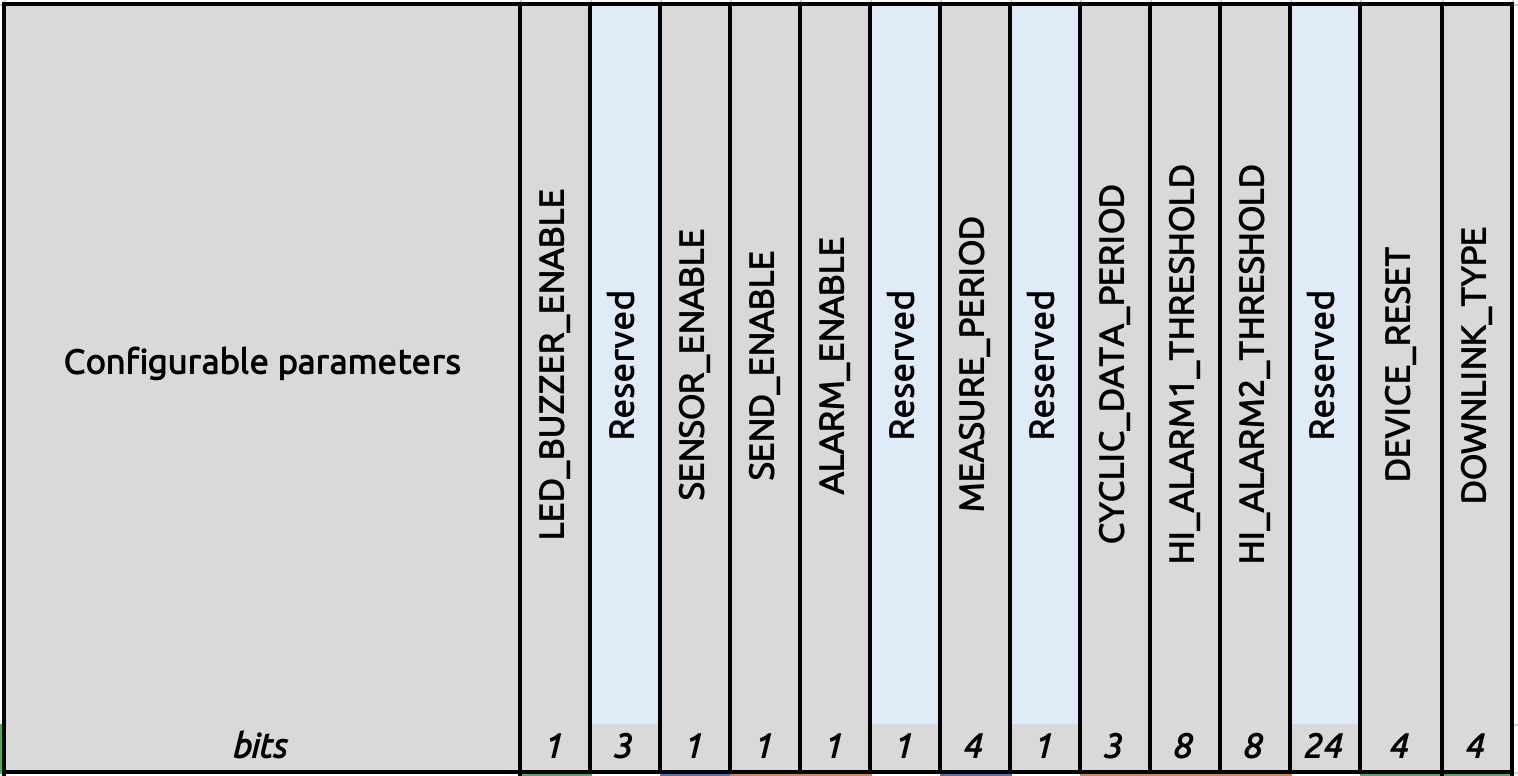
Below is the table to explain in detail the meaning of each configuration parameter and its default value.
|
Parameters |
Description |
Possible values |
Default values |
Length (in bits) |
|
LED_BUZZER_ENABLE |
Flag to enable/disable LED and Buzzer interactions for action not triggered by the button. |
0b0 = false, LEDs are OFF 0b1 = true, LEDs are ON |
0b1 = true |
1 |
|
SENSOR_ENABLE |
Enable Gas Sensing Module to measure |
0b0 = false, gas sensing module is disabled 0b1 = true, gas sensing module is enabled |
0b1 = true |
1 |
|
SEND_ENABLE |
Enable sending data in a cyclic period |
0b0 = false, disabled 0b1 = true, enabled |
0b1 = true |
1 |
|
ALARM_ENABLE |
Enable alarm processing and sending data |
0b0 = false, disabled Alarm 0b1 = true, enabled Alarm |
0b0 = false, disabled Alarm |
1 |
|
MEASURE_PERIOD |
Period for sensing module to wake up and take measurement |
0b0000 = every 1s 0b0001 = every 2s 0b0010 = every 5s 0b0011 = every 10s 0b0100 = every 20s 0b0101 = every 30s 0b0110 = every 1min 0b0111 = every 2min 0b1000 = every 5min 0b1001 = every 10min 0b1010 = every 20min 0b1011 = every 30min 0b1100 = every 1h 0b1101 = every 2h 0b1110 = every 3h 0b1111 = every 6h |
0b1001 = every 10min |
4 |
|
CYCLIC_DATA_PERIOD |
Period to send CYCLIC_DATA |
0b000 = every 10min 0b001 = every 30min 0b010 = every 1h 0b011 = every 2h 0b100 = every 3h 0b101 = every 6h 0b110 = every 12h 0b111 = every 24h |
0b000 = every 10min |
3 |
|
HI_ALARM1_THRESHOLD |
Hi alarm threshold #1 (it must be < HI_ALARM2_THRESHOLD) |
8-bit unsigned integer Formula: (8-bit_VALUE/2)= real_VALUE_in_its unit** Example: 0b01110100 = 0x74 = 116 => (116 / 2) = 58ppm |
0b00001010 = 5ppm |
8 |
|
HI_ALARM2_THRESHOLD |
Hi alarm threshold #2 |
8-bit unsigned integer Formula: (8-bit_VALUE/2)= real_VALUE_in_its unit** Example: 0b01110100 = 0x74 = 116 => (116 / 2) = 58ppm |
0b00010100 = 10ppm |
8 |
|
DEVICE_RESET |
Once this parameter is set, the device shall restart after receiving the Downlink. After restarting, the value turns to 0b0000 automatically. |
0b1010 = 0xA = Force device reset others = do nothing |
others = do nothing |
4 |
|
DOWNLINK_TYPE |
Downlink type |
4-bit unsigned integer |
0b0000 |
4 |
EXAMPLE FOR DOWNLINK TYPE = 0
If you plan to change the MEASURE_PERIOD = 30 minutes and CYCLIC_DATA_PERIOD = 30 minutes then please enter your desired values, guided by the table below:
|
Parameter |
Desired setting value |
Setting Value (in binary) |
Length (in bits) |
|
LED_BUZZER_ENABLE |
0b1 = enable LED and Buzzer |
1 |
1 |
|
Reserved |
0 |
000 |
3 |
|
SENSOR_ENABLE |
0b1 = enable sensor module running |
1 |
1 |
|
SEND_ENABLE |
0b1 = enable to send cyclic data |
1 |
1 |
|
ALARM_ENABLE |
0b0 = false, disabled Alarm |
0 |
1 |
|
Reserved |
0 |
0 |
1 |
|
MEASURE_PERIOD |
0b1011 = every 30min |
1011 |
4 |
|
Reserved |
0 |
0 |
1 |
|
CYCLIC_DATA_PERIOD |
0b001 = every 30min |
001 |
3 |
|
HI_ALARM1_THRESHOLD |
0b00001010 = 5ppm |
00001010 |
8 |
|
HI_ALARM2_THRESHOLD |
0b00010100 = 10ppm |
00010100 |
8 |
|
Reserved |
0 |
000000000000000000000000 |
24 |
|
DEVICE_RESET |
0b0000 = do nothing |
0000 |
4 |
|
DOWNLINK_TYPE |
0b0000 |
0000 |
4 |
Then you will get the final configuration code as below:
1000 1100 1011 0001 0000 1010 0001 0100 0000 0000 0000 0000 0000 0000 0000 0000 = 8CB10A1400000000
5.2 Downlink type = 5
With this downlink, the user can write the configuration to any address on the memory map of the device. Please refer to the memory map of the device to understand what parameters can be written.
The length of the configuration parameter can be 1, 2 bytes, or 4 bytes, but the total length of the Downlink payload must equal 64 bits (8 bytes). Please see below the downlink format for both types.
Downlink type 5 for the parameter of 2 bytes length:
|
Payload |
PRM_ADDRESS |
PRM_LENGTH |
PRM_VALUE |
reserved |
DOWNLINK_TYPE |
|
bits |
8 |
8 |
16 |
28 |
4 |
|
Value |
yes |
0x02 = 2 |
yes |
zeros |
0b0101 = 5 |
Downlink type 5 for the parameter of 4 bytes length:
|
Payload |
PRM_ADDRESS |
PRM_LENGTH |
PRM_VALUE |
reserved |
DOWNLINK_TYPE |
|
bits |
8 |
8 |
32 |
12 |
4 |
|
Value |
yes |
0x04 = 4 |
yes |
zeros |
0b0101 = 5 |
Where:
- PRM_ADDRESS: address of the configuration parameter in the memory map of the device;
- PRM_LENGTH: is the length of that parameter, in bytes;
- PRM_VALUE: is the value the user wants to write to that parameter;
- reserved: a series of bits of zero to fulfill the downlink so that it has the total length = 64 bits (8 bytes)
EXAMPLE FOR DOWNLINK TYPE = 5
Here is the list of parameters of WSLRW-G4 or WSLRWEX-G that can be configured via Downlink type = 5 and the examples of the downlink payload on the right-most side column. It is the example value, not the default value of the device. Please check the memory map of the device for more detail about the parameters.
Note: the total length of the downlink must be equal to 8 bytes
|
PARAMETER |
DATA TYPE OF PARAMETER |
PRM_ADDRESS |
PRM_LENGTH |
PRM_VALUE |
DOWNLINK_TYPE |
PAYLOAD OF DOWNLINK (IN HEXA) |
|
(bytes) |
|
1 |
1 |
4 |
2 |
8 |
|
CONSTANT_A |
Float |
0x4E |
0x04 = 4 |
0x3F8CCCCD = 1.1 |
0x0005 |
4E043F8CCCCD0005 |
|
CONSTANT_B |
Float |
0x50 |
0x04 = 4 |
0x3E4CCCCD = 0.2 |
0x0005 |
50043E4CCCCD0005 |
|
HIGH_CUT |
Float |
0x52 |
0x04 = 4 |
0x447A0000 = 1000 |
0x0005 |
5204447A00000005 |
|
LOW_CUT |
Float |
0x54 |
0x04 = 4 |
0x00000000 = 0 |
0x0005 |
5404000000000005 |
|
SENSOR+AMPLIFIER_SENSITIVITY |
Uint32 |
0x58 |
0x04 = 4 |
0x41300000 = 11 |
0x0005 |
5804413000000005 |
5.3 Free online data conversion tools
- To convert from Float to Hex and vice versa, users may use this free online tool: https://gregstoll.com/~gregstoll/floattohex/
- To convert a decimal number to Hex, the user may use this free online tool: https://www.binaryhexconverter.com/decimal-to-hex-converter
6. Reed switches
The LoRaWAN sensor typically comes with at least one reed switch for user manipulation during commissioning or maintenance.
Some other versions come with 02 reed switches.
The WSLRW-G4 or WSLRWEX-G comes with one reed switch; please find below the functions of this switch.
|
EVENT |
PRE-CONDITION |
ACTION |
LED STATUS |
ACTIVITIES |
POST-CONDITION |
|
FORCE_DATA |
Any state |
Move Magnet Key to the contact point of REED SWITCH. Led blink SKY BLUE, move Magnet Key away. |
Blink SKY BLUE |
the device will send the uplink message FORCE_DATA |
Back to the previous state |
|
PARAMETERS_UPDATE |
Any state |
Move Magnet Key to the contact point of REED SWITCH. Led blink SKY BLUE, hold Magnet Key 5s. Led blink PURPLE, move Magnet Key away. |
Blink PURPLE |
the device will send the uplink message PARAMETER_UPDATE |
Back to the previous state |
Payload for LoRaWAN Tilt Sensor WSLRW-AG
Payload WSLRW-AG | Firmware 2
1. Payload document is applied for the following products
| Item code | HW Version | Firmware Version | Remarks |
| WSLRW-AG | 1 | 2 |
2. Changes information in this version v.s previous version
| Item | Changes | Changed by | Changed Date | Approved by | Approved Date |
| 2 | Improve accuracy and resolution on FW 2 | P.N.Diep | 07-09-2022 | N.V.Loc | 07-09-2022 |
| 1 | Initial version FW 1 | P.N.Diep | 01-06-2022 | N.V.Loc | 02-06-2022 |
The approved date is also the release date of this document.
3. Payload for Uplink messages
START_UP message
| When? | Purpose | Wait for Downlink? | LED color |
| This message will be sent once after 60 seconds from power-up the device | To understand when the device was powered up | YES |
Blink WHITE |
| Payload | EVENT_ID | HW_VERSION | FW_VERSION | CURRENT_CONFIGURATION |
| bits | 4 | 4 | 8 | 64 |
| value | 0b0000 = 0 | yes | yes | yes |
PARAMETER_UPDATE message
| When? | Purpose | Wait for Downlink? | LED color |
|
When the reed switch is activated by the magnet key. How? Move Magnet Key to the contact point of REED SWITCH. Led blink SKY BLUE, hold Magnet Key 5s. Led blink PURPLE, move Magnet Key away. |
To send the new configuration to the device via downlink | YES |
Blink PURPLE |
| Payload | EVENT_ID | HW_VERSION | FW_VERSION | CURRENT_CONFIGURATION |
| bits | 4 | 4 | 8 | 64 |
| value | 0b0001 = 1 | yes | yes | yes |
FORCE_DATA message
| When? | Purpose | Wait for Downlink? | LED color |
|
When the reed switch is activated by the magnet key. How? Move Magnet Key to the contact point of REED SWITCH. Led blink SKY BLUE, move Magnet Key away. |
To get the instant measured value from the device for calibration and validation. | YES |
Blink SKY BLUE |
| Payload | EVENT_ID | SENSOR_ERROR | reserved | BATTERY_LEVEL | reserved | X_TILT_VALUE_X10 | Y_TILT_VALUE_X10 | Z_TILT_VALUE_X10 |
| bits | 4 | 1 | 5 | 2 | 4 | 16 | 16 | 16 |
| value | 0b0010 = 2 | yes | zeros | yes | zeros | yes | yes | yes |
CYCLIC_DATA message
| When? | Purpose | Wait for Downlink? | LED color |
| This message will be sent in the pre-defined cycle. | To get the measured value from the device in the pre-defined cycle. | YES |
Blink SKY BLUE |
| Payload | EVENT_ID | SENSOR_ERROR | reserved | BATTERY_LEVEL | reserved | X_TILT_VALUE_X10 | Y_TILT_VALUE_X10 | Z_TILT_VALUE_X10 |
| bits | 4 | 1 | 5 | 2 | 4 | 16 | 16 | 16 |
| value | 0b0011 = 3 | yes | zeros | yes | zeros | yes | yes | yes |
4. Payload Fields of Uplink
Below is an explanation of the payload fields in the uplink messages.
|
Data name |
Description |
Encoding or Possible values |
Length (in bits) |
|
EVENT_ID |
Unique ID identifying the device event |
4-bit unsigned integer 0 = START_UP 1 = PARAMETERS_UPDATE 2 = FORCE_DATA 3 = CYCLIC_DATA |
4 |
|
HW_VERSION |
HW_VERSION = HW_VERSION value in EEPROM set in production |
4-bit unsigned integer 1..15 |
4 |
|
FW_VERSION |
Indicate the FW version. Refer to the FW release note |
8-bit unsigned integer 1..255 |
8 |
|
CURRENT_CONFIGURATION |
The current configuration code of the device |
64-bit encoded field Refer to the Downlink section |
64 |
|
SENSOR_ERROR |
Indicate the sensor error or not |
0b0 = no sensor's error 0b1 = sensor's error |
1 |
|
BATTERY_LEVEL |
Battery level |
2-bit unsigned integer 0 to 3 0: 10% 1: 30% 2: 60% 3: 99% |
2 |
| X_TILT_VALUE_X10 |
X Tilt value |
16-bit signed integer X_TILT_VALUE = X_TILT_VALUE_X10 / 10 Range: -90.0 to 90.0 |
16 |
| Y_TILT_VALUE_X10 |
Y Tilt value |
16-bit signed integer Y_TILT_VALUE = Y_TILT_VALUE_X10 / 10 Range: -90.0 to 90.0 |
16 |
| Z_TILT_VALUE_X10 |
Z Tilt value |
16-bit signed integer Z_TILT_VALUE = Z_TILT_VALUE_X10 / 10 Range: -90.0 to 90.0 |
16 |
5. Payload for Downlink messages
Users can use a downlink message to change the configuration of the device. There are 02 types of downlink messages:
- Downlink type = 0: Write the configuration for the specific type of LoRaWAN sensor. The format is fixed for each type of sensor.
- Downlink type = 5: Write a value to any address of the configuration parameter of the LoRaWAN sensor. This method is generic and can be applied to any type of LoRaWAN sensor, the user just needs to know the memory map of the sensor.
5.1 Downlink type = 0

Below is the table to explain in detail the meaning of each configuration parameter and its default value.
|
Parameters |
Description |
Possible values |
Default values |
Length (in bits) |
|
LED_BUZZER_ENABLE |
Flag to enable/disable LED and Buzzer interactions for action not triggered by the button. |
0b0 = false, LEDs are OFF 0b1 = true, LEDs are ON |
0b1 = true |
1 |
|
MEASURE_PERIOD |
Period for sensing module to wake up and take measurement |
0b0000 = every 1s 0b0001 = every 2s 0b0010 = every 5s 0b0011 = every 10s 0b0100 = every 20s 0b0101 = every 30s 0b0110 = every 1min 0b0111 = every 2min 0b1000 = every 5min 0b1001 = every 10min 0b1010 = every 20min 0b1011 = every 30min 0b1100 = every 1h 0b1101 = every 2h 0b1110 = every 3h 0b1111 = every 6h |
0b1001 = every 10min |
4 |
|
CYCLIC_DATA_PERIOD |
Period to send CYCLIC_DATA |
0b000 = every 10min 0b001 = every 30min 0b010 = every 1h 0b011 = every 2h 0b100 = every 3h 0b101 = every 6h 0b110 = every 12h 0b111 = every 24h |
0b000 = every 10min |
3 |
|
DEVICE_RESET |
Once this parameter is set, the device shall restart after receiving the Downlink. After restarting, the value turns to 0b0000 automatically. |
0b1010 = 0xA = Force device reset others = do nothing |
others = do nothing |
4 |
|
DOWNLINK_TYPE |
Downlink type |
4-bit unsigned integer |
0b0000 |
4 |
EXAMPLE FOR DOWNLINK TYPE = 0
If you plan to change the MEASURE_PERIOD = 30 minutes and CYCLIC_DATA_PERIOD = 30 minutes then please enter your desired values, guided by the table below:
|
Parameter |
Desired setting value |
Setting Value (in binary) |
Length (in bits) |
|
Reserved |
0 |
00000000000000000000000000000000000000000000 |
44 |
|
LED_BUZZER_ENABLE |
0b1 = enable LED and Buzzer |
1 |
1 |
|
Reserved |
0 |
000 |
3 |
|
MEASURE_PERIOD |
0b1011 = every 30min |
1011 |
4 |
|
Reserved |
0 |
0 |
1 |
|
CYCLIC_DATA_PERIOD |
0b001 = every 30min |
001 |
3 |
|
DEVICE_RESET |
0b0000 = do nothing |
0000 |
4 |
|
DOWNLINK_TYPE |
0b0000 |
0000 |
4 |
Then you will get the final configuration code as below:
0000 0000 0000 0000 0000 0000 0000 0000 0000 0000 0000 1000 1011 0001 0000 0000 = 000000000008B100
5.2 Downlink type = 5
With this downlink, the user can write the configuration to any address on the device's memory map. Please refer to the device's memory map to understand what parameters can be written.
The length of the configuration parameter can be 1, 2 bytes, or 4 bytes, but the total length of the Downlink payload must equal 64 bits (8 bytes). Please see below the downlink format for both types.
Downlink type 5 for the parameter of 2 bytes length:
|
Payload |
PRM_ADDRESS |
PRM_LENGTH |
PRM_VALUE |
reserved |
DOWNLINK_TYPE |
|
bits |
8 |
8 |
16 |
28 |
4 |
|
Value |
yes |
0x02 = 2 |
yes |
zeros |
0b0101 = 5 |
Downlink type 5 for the parameter of 4 bytes length:
|
Payload |
PRM_ADDRESS |
PRM_LENGTH |
PRM_VALUE |
reserved |
DOWNLINK_TYPE |
|
bits |
8 |
8 |
32 |
12 |
4 |
|
Value |
yes |
0x04 = 4 |
yes |
zeros |
0b0101 = 5 |
Where:
- PRM_ADDRESS: address of the configuration parameter in the memory map of the device;
- PRM_LENGTH: is the length of that parameter, in bytes;
- PRM_VALUE: is the value the user wants to write to that parameter;
- reserved: a series of bits of zero to fulfill the downlink so that it has the total length = 64 bits (8 bytes)
EXAMPLE FOR DOWNLINK TYPE = 5
Here is the list of parameters of WSLRW-AG that can be configured via Downlink type = 5 and the examples of the downlink payload on the right-most side column. It is the example value, not the default value of the device. Please check the device's memory map for more detail about the parameters.
Note: the total length of the downlink must be equal to 8 bytes
|
PARAMETER |
DATA TYPE OF PARAMETER |
PRM_ADDRESS |
PRM_LENGTH |
PRM_VALUE |
DOWNLINK_TYPE |
PAYLOAD OF DOWNLINK (IN HEXA) |
|
(bytes) |
|
1 |
1 |
4 |
2 |
8 |
|
ADAPTIVE DATA RATE |
Uint16 |
0x40 |
0x02 = 2 |
0x00000001 = 1 | 0x0005 |
4002000000010005 |
5.3 Free online data conversion tools
- To convert from Float to Hex and vice versa, users may use this free online tool: https://gregstoll.com/~gregstoll/floattohex/
- To convert a decimal number to Hex, the user may use this free online tool: https://www.binaryhexconverter.com/decimal-to-hex-converter
6. Reed switches
The LoRaWAN sensor typically comes with at least one reed switch for user manipulation during commissioning or maintenance.
Some other versions come with 02 reed switches.
The WSLRW-AG comes with one reed switch; please find below the functions of this switch.
|
EVENT |
PRE-CONDITION |
ACTION |
LED STATUS |
ACTIVITIES |
POST-CONDITION |
|
FORCE_DATA |
Any state |
Move Magnet Key to the contact point of REED SWITCH. Led blink SKY BLUE, move Magnet Key away. |
Blink SKY BLUE |
the device will send the uplink message FORCE_DATA |
Back to the previous state |
|
PARAMETERS_UPDATE |
Any state |
Move Magnet Key to the contact point of REED SWITCH. Led blink SKY BLUE, hold Magnet Key 5s. Led blink PURPLE, move Magnet Key away. |
Blink PURPLE |
the device will send the uplink message PARAMETER_UPDATE |
Back to the previous state |