GENERAL GUIDE FOR ICONNECTOR STHC
This chapter is to provide the general guides for all kind of iConnector with SKU: STHC. It includes the following guides: * Principle of operation of iConnector STHC; * How to Wiring the iConnector * How to Config iConnector via offline cable; * How to Configure Modbus commands for iConnector; * How to Configure Alarms & Event; * How to Trouble-shoot iConnector; ...
- General Information
- I. Specification of iConnector STHC
- II. Principle of operation of iConnector STHC
- III. Offline configuration for iConnector
- IV. Insert SIM Card for Cellular iConnector
- V. Installation iConnector STHC
- VI. How to add iConnector STHC to Globiots Server System?
- VII. Modbus Configuration for iConnector STHC on Globiots
- VIII. Parameter Configuration for iConnector STHC on Globiots
- IX. Alarm & Event Configuration for iConnector STHC on Glbiots
- X. Configuring special functions of iConnector on Globiots
- XI. Troubleshooting iConnector and Globiots
- Manual of STHC-ISGWET-WS433-CL-04 | FW8
- I.QUICK GUIDE | STHC-ISGWET-WS433-CL-04 | FW8
- II. MAINTENANCE | STHC-ISGWET-WS433-CL-04 | FW8
- III. ADVANCE GUIDE | STHC-ISGWET-WS433-CL-04 | FW8
- IV. PRODUCT SPECIFICATIONS | STHC-ISGWET-WS433-CL-04 | FW8
- V. WARRANTY & SUPPORT | STHC-ISGWET-WS433-CL-04 | FW8
General Information
| STHC-MN01-EN-01 |
JUL-2020 |
This document is applied for the following products
| SKU | STHC | HW Ver. | 3.3 | FW Ver. | 3.5 |
A. Functions Change Log
| HW Ver. | FW Ver. | Release Date | Functions Change |
| 3.3 | 3.5 | Aug-2020 |
B. Support contacts
|
Manufacturer
Daviteq Technologies Inc Email: info@daviteq.com | www.daviteq.com
|
Distributor in Australia and New Zealand
Templogger Pty Ltd Tel: 1800 LOGGER Email: contact@templogger.net |

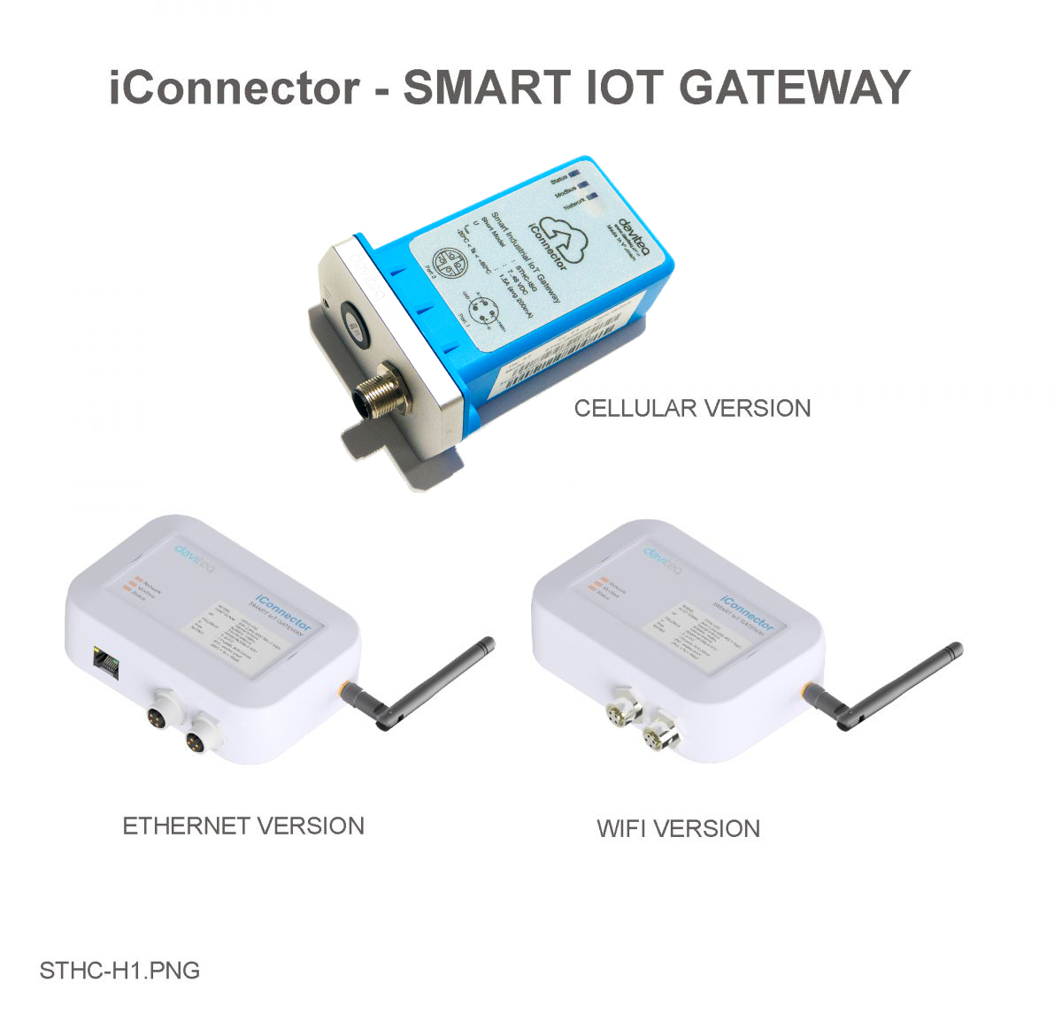
I. Specification of iConnector STHC
1.1 Introduction
STHC is a Smart IoT Gateway, aka iConnector, a main component in any IoT application. iConnector has a role to connect the real World's things like sensors, meters, ,machines...to server system for data logging, data analytics, monitoring & controls...iConnector support multiple Industrial Fieldbus like Modbus, EthernetIP, Profinet, CClink, Wireless sensor network...It connects to server system via LAN/WAN as Ethernet, WiFi or Cellular.
1.2 Specification
| Host Communication Cellular type | GPRS Quadband (850/900/1800/1900)/3G-Dual band (2100/900)/3G- Penta Band (2100/1900/850/850Japan/900/800Japan),standard internal antenna, optional external antenna |
| Host Communication Etherner type | 01 x RJ45 port, 10Mbps |
| Host Communication WiFi type | 802.11b/g/n, 2.4Ghz,internal antenna |
| GPS | option, only available on GPRS version or 3G-Penta band version |
| Host communication supports | TCP/IP, UDP/IP, FTP, HTTPS, SNMP... |
| Fieldbus communcation | ModbusRTU x 01 port, 31 slaves, max 19.2 kpbs |
| Vietnam Type Approval Cerification | QCVN 54:2011/BTTTT, QCVN 15:2015/BTTTT (DAVITEQ B00122019) |
| Optional | Integrated wireless co-ordinator with external antenna or internal antenna |
| Optional | Internal buzzer (to replace Relay 1) |
| Power supply | 7..48VDC, avg 200mA, peak 1.5A |
| Back-up battery | Lithium Super Capacitor |
| On-board memory & sensors | 2MB Flash, PCB temperature sensor |
| Electrical connectors | M12, 4-pin, coding A or 9mm Power Plug and USB port |
| SIM slot | 01 x micro-SIM (cellular versions only) |
| Included accessories | mounting bracket for wall mount (cellular version only) |
| Operating Temperature/Humidity | -20 .. + 60 degC / 95%RH, non-condensing |
| Housing/Protection | Aluminum+Polycarbonate for Cellular version, anti-UV plastic for Ethernet/WiFi version. All version is IP67 protection |
| Dimension | H106xW73xD42 for Cellular version, H130xW90xD40 for Ethernet/WiFi versions |
| Net weight | 190 grams for Cellular version, 350 grams Ethernet/WiFi versions |
| Relay outputs | 02 x relay SPST NO contact, 125VAC@0.3A or 24VDC@1A |
II. Principle of operation of iConnector STHC
2.1 General operation principles of iConnector
2.1.1 LED meaning
2.1.1.1 LED status
| Status | Meaning |
| Fixed ON | iConnector has been supplied with external power |
| Blinking (4 seconds blink 1 time) | Without external power, iConnector is using battery. |
| Blinking (2 seconds blink 1 time) | Low battery warning (Used for type D battery version) |
2.1.1.2 LED modbus
| Status | Meaning |
| Fixed ON | Modbus connected |
| Blinking (1 seconds blink 2 time) | Connection errors (wrong configuration of baudrate, noise, …) |
| OFF | No modbus connection |
2.1.1.3 LED network
| Status | Meaning |
| Fixed ON | Connecting with Globiots |
| Blinking (1s change state) | Initializing wifi generator, waiting for configuration via phone or modbus tool (For iConnector wifi) |
| OFF | No connection with Globiots |
2.1.2 Memory Map
|
Address |
Size (bytes) |
Memory type |
Read/Write |
Description |
|
0-0x1FFF |
8096 |
FLASH |
R/W |
Save active configuration, do not allow log, realtime. |
|
0x2000-0x22FF |
768 |
RAM |
R |
Save data read from modbus slaves. |
|
0x2300-0x24FF |
512 |
RAM |
R |
The intrinsic data of iConnector |
|
0x3000-0x30FF |
256 |
RAM |
R/W |
|
|
0x5000-0x50FF |
256 |
FLASH |
R/W |
|
|
0x6000-0x6FFF |
4096 |
RAM |
R |
Save data read from modbus slaves |
- Data address area: 0x2000-0x22FF (768 bytes), and 0x6000-0x6FFF (4096 bytes).
- Controller address area: 0x3000-0x30FF (256 bytes, without flash storage), and 0x5000-0x50FF (256 bytes, with flash storage).
Address area 0x5000-0x50FF
- 256 bytes;
- Save in flash (when power is lost, will keep the same value);
- Allows reading, and writing from Globiots;
- Allow log (realtime);
- Allows Modbus write to Slaves;
- It is not allowed to store data read from Modbus Slaves.
NOTE:
Flash recorded about 100,000 times will be damaged so do not use this area to contain the value is changed several times.
2.1.3 Logged data
- Up to 20 different log cycles;
- 320 log parameters maximum for all log cycles.
- Up to 120 log parameters per log cycle.
2.1.4 Modbus
- Support modbus RTU.
- Address slave 1… 247.
- It is not allowed to set address slave = 0.
- Baudrate 4800/9600/19200.
- Parity none / odd / even.
- Up to 100 modbus instructions.
- The address area for storing read data: 0x2000-0x22FF (768 bytes), and 0x6000-0x6FFF (4096 bytes).
- Controller address area: 0x3000-0x30FF (256 bytes, without flash storage), and 0x5000-0x50FF (256 bytes, with flash storage).
2.1.5 Realtime
- Read up to 200 parameters.
- If all parameters are float (4 bytes) then read up to 140 parameters.
- The fastest realtime sending frequency is 1 second.
2.1.6 Alarm
- Up to 28 alarms.
- Supported data types:
|
PrmType |
Description |
# Byte |
Range |
|
1 |
BYTE |
1 |
0 to 255 |
|
2 |
UINT16 |
2 |
0 to 65,535 |
|
3 |
UINT32 |
4 |
0 to 4,294,967,295 |
|
4 |
FLOAT |
4 |
-/+3.40282347 * (10^+38) |
|
5 |
INT16 |
2 |
-32,768 to 32,767 |
|
6 |
INT32 |
4 |
-2,147,483,648 to 2,147,483,647 |
2.1.7 Event
- The event table is 1024 bytes.
- The number of events depends on the short length of the event configured.
- Supported data types:
|
PrmType |
Description |
# Byte |
Range |
|
1 |
BYTE |
1 |
0 to 255 |
|
2 |
UINT16 |
2 |
0 to 65,535 |
|
3 |
UINT32 |
4 |
0 to 4,294,967,295 |
|
4 |
FLOAT |
4 |
-/+3.40282347 * (10^+38) |
|
5 |
INT16 |
2 |
-32,768 to 32,767 |
|
6 |
INT32 |
4 |
-2,147,483,648 to 2,147,483,647 |
2.1.8 Health data
- Every 15 seconds send health pack 1 time.
2.1.9 Relay
There are 2 relays:
- Relay control address 1: 0x3100.
- Relay control address 2: 0x3101.
2.2 iConnector Cellular
2.2.1 GSM signal quality
|
Value |
RSSI dBm |
Condition |
|
0-9 |
≤-113 to -95 |
Marginal |
|
10-14 |
-93 to -85 |
OK |
|
15-19 |
-83 to -75 |
Good |
|
20-31 |
-73 to ≥-51 |
Excellent |
|
99 |
|
not known or undetectable |
2.2.2 GSM status
|
Value |
Status |
|
0 |
Connect to the server: OK |
|
1 |
Connect to network operator: OK, the server is not connected yet |
|
2 |
Communicate with GSM modem with AT command: OK |
|
3 |
The GSM modem is starting |
2.2.3 APN Configuration
- Use the iConnector Config Software to connect and configure iConnector
Refer to section 5 for more details about how to use Configuration Cable.
Refer to section 6 for more details about how to insert SIM Card.
Refer here for more details on how to add sensor to the iConnector integrated Co-ordinator.
- Open the 2G / 3G tab, then fill in the APN information of the SIM Card (APN, Username, Password,..) in Setting. Finally click Sync to configure
2.3 iConnector Ethernet
2.3.1 What is TCP/IP ?
2.3.2 Configure with iConnector Config software
Refer to section 5 for more details on how to use Configuration Cable
3.3.2.1 Ethernet tab
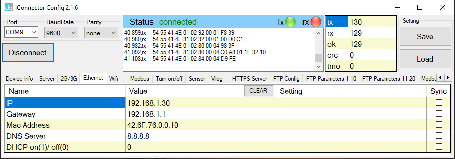
| Name | Description |
| IP | Static IP configuration for iConnector. Example: 192.168.1.30 |
| Gateway | Configure gateway |
| DNS Server | Configure DNS Server |
| DHCP |
0 (Off) / 1 (On) If DHCP = 0, it's mean Not using DHCP → Static IP |
3.3.2.2 Modbus-TCP-Server tab
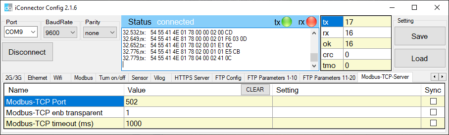
| Name | Description |
| Modbus-TCP Port | Configure the receiving port, for example 502 |
| Modbus-TCP enb transparent |
1 : To run transparent, interrupt modbus RTU poll. 0 : Run modbus RTU poll as normal iConnector, not transparent |
| Modbus-TCP timeout (ms) | Used for modbus TCP Server |
2.3.3 Description of transparent mode operation (Modbus-TCP enb transparent = 1)
Suppose we have: Static IP address: 192.168.1.30 | Port 502
1. iConnector is connected to the Modbus RTU with electric meters, devices, ... via RS485 port;
2. Software / device / PLC ... with Modbus TCP Client connected to iConnector (role as TCP Server) at Static IP address 192.168.1.30 | Port 502 in internal network;
3. TCP Client sends command to iConnector;
4. iConnector transfers commands from Modbus TCP to RTU and sends to devices and clocks via RS485 port;
5. iConnector waits for the devices to respond;
6. iConnector transfers the response from the RTU to the Modbus TCP and then sends it back to the TCP Client;
7. TCP Client actively closes the connection if it no longer sends command to iConnector.
2.3.4 Run Modbus RTU as normal iConnector (Modbus-TCP enb transparent = 0)
3.3.4.1 TCP Client connects to iConnector via internet
1. iConnector needs static IP configuration, For example: IP 192.168.1.30 | Port 502
2. The external internet network must also have a static IP, Example: IP 118.69.111.101
3. Network administrator must implement NAT port 502, TCP to IP of iConnector
4. At that time, TCP Client will connect to IP address 118.69.111.101 | Port 502
3.3.4.2 TCP Client read/write parameters on the iConnector memmap
iConnector supports command 3 (0x03) for read, command 16 (0x10) for writing.
The Unit Identifier is 31 (0x1F) to read and write memmap iConnector, not 31 will make devices transparent read and write via RS485.
These commands are changed to match the address of iConnector (address in bytes but not in registers like modbus).
1. Command 3:
Modbus TCP is:
0001 0000 0006 1F 03 006B 0003
- 0001: Transaction Identifier
- 0000: Protocol Identifier
- 0006: Message Length (6 bytes to follow)
- 1F: The Unit Identifier (31 = 1F hex)
- 03: The Function Code (read Analog Output Holding Registers)
- 2000: The Data Address of the first register requested → This will be the address on the memmap
- 0003: The total number of registers requested. (read 3 registers 40108 to 40110) →This number 3 will be 3 bytes, not 3 registers anymore.
At that time iConnector will respond to data of 3 bytes, not 6 bytes
2. Command 16:
Modbus TCP is:
0002 0000 0009 1F 10 3000 0002 04 000A
- 0002: : Transaction Identifier
- 0000: Protocol Identifier
- 0009: Message Length (6 bytes to follow)
- 1F: The Unit Identifier (31 = 1F hex)
- 10: The Function Code 16 (Write Function)
- 3000: The Data Address of the first register requested → This will be the address on the memmap
- 0002: The number of registers to write → This is the length to write is 2 bytes, not 2 more registers.
- 04: The number of data bytes to follow
- 000A: The value to write to register → data 2 bytes need to write
2.4 iConnector Wifi
2.4.1 Configure using the iConfig app on the phone
Please refer to how to configure using iConfig app with the following link:
iConfig Mobile app for Android
2.4.2 Configure using the Configuration Cable
Refer to III. Offline configuration for iConnector for more details on how to use Configuration Cable
Step 1: Open the configuration tool and switch to the Wifi tab;
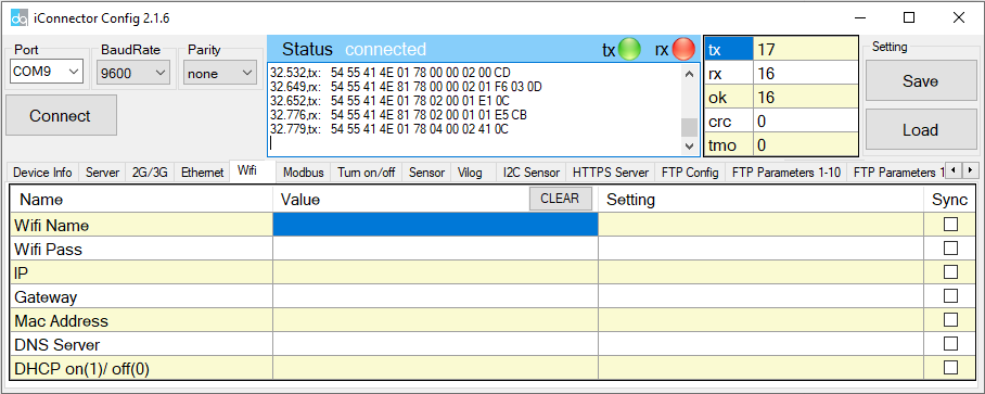
Step 2: Step 2: Configure the Wifi Name and Password that iConnector Wifi will connect to;
Step 3: Check the Network LED. If the LED is always on, the connection is successful.
2.4.3 Modbus-TCP-Server Configuration
Please refer to the Modbus-TCP-Server configuration section in section 4.3.
III. Offline configuration for iConnector
iConnector need to be configured properly so that it is able to connect to Globiots Server successfully;
3.1 Preparation
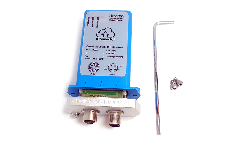
3.1.1 Configuration Cable
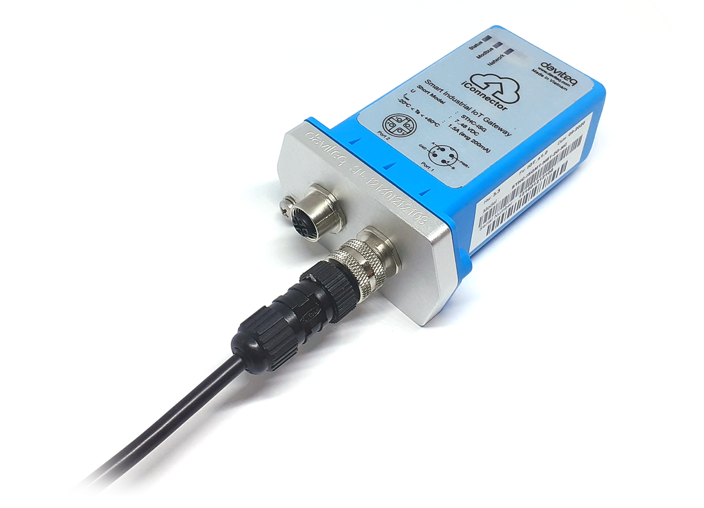
- iConnector need to be configured initially before operation, by using a configuration cable as below:
|
Item code |
Description |
|
RS485-FM12-USB-1 |
RS485/USB multi-purpose Configuration cable with connector m12 male, female and flying leads, with Power adapter 12VDC/2.0A |
Below picture is illustration of this configuration cable.
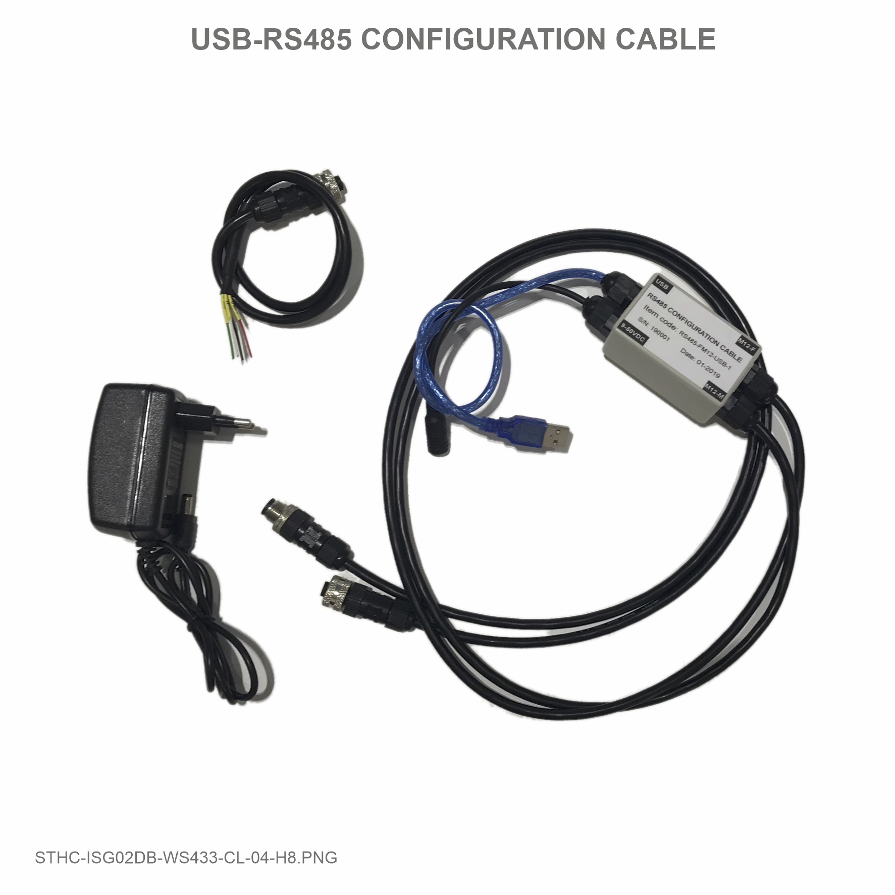
The configuration cable has 04 connectors:
* 1st-connector is M12-F connector with 4 pin inside (A, B, PWR & GND): to connect the RS485 port of iConnector;
* 2nd-connector is M12-M connector with 4 pin inside (A, B, PWR & GND): to connect to other devices with RS485 port, but its connector is M12-F;
* 3rd-connector is USB Type A plug: this is to connect to the USB port of Computer;
* 4th-connector is DC Socket 5.5 mm for Powering the converter circuit and iConnector or other device connected to this tool. This DC jack will be plugged by the plug of AC Power adapter. AC power adapter can be 12V/2A or 24VDC/1A;
* There is a flying lead with Connector M12 to allow customer connect to other device with RS485 port but no M12 connector, like IO Module (SKU# STHM-)....
3.1.2 Offline Configuration Software:
- To configure the iConnector, there is a Software run on Windows OS (Window 10 is recommended);
- Please download the software at link below: https://filerun.daviteq.com/wl/?id=lNjzZbDo7Jwyr1x8DAD3x620tNK5u8lF
Any desktop or laptop computer with USB-A port and Windows 10 OS can be used with this Software
- Unzip the file, it will extract 04 files as below picture:
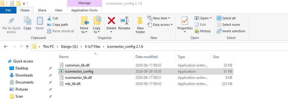
- Double-click the application file, named: iconnector_config to run the application. You will see the application as below.

There should be the COM port when you plug in the USB plug of configuration tool. If there is no, please:
* Install the COM Port driver as below instruction 3.1.3;
* After that close and open the software again.
3.1.3 Install the Driver for COM Port:
In case your computer has not got the driver, please follow these step to install the driver for Window 10:
After install the driver successfully, please close and open the software again.
3.2 Configuration Steps:
Please follow these steps:
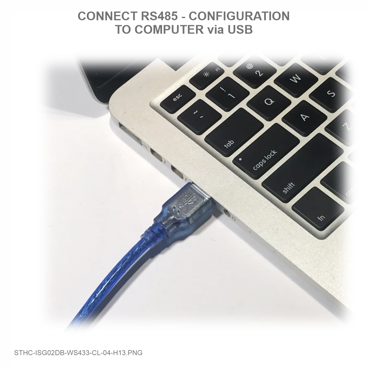
Step 1: Plug the USB
|
Step 2: Powering
|
Step 3: Connect to iConnector
The LED "Status" on iConnector must be turn ON, that meant it is powered!
|
|

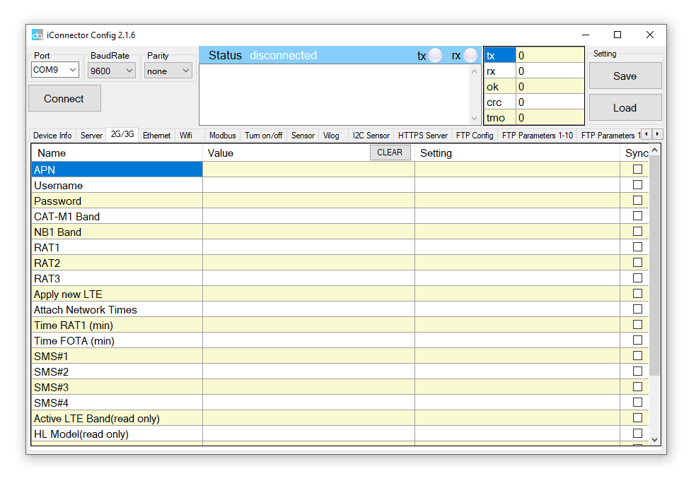
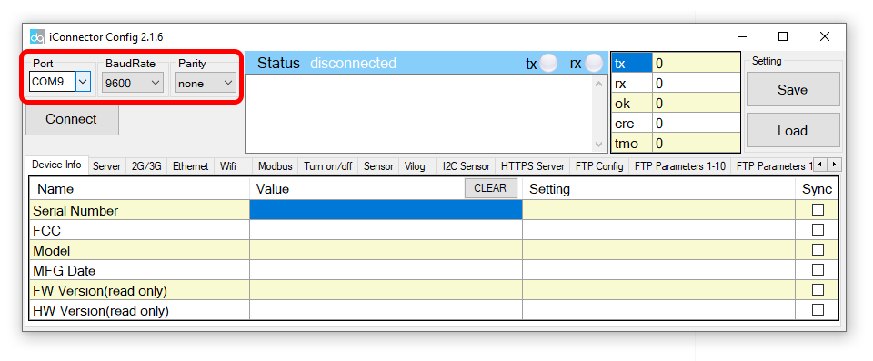
Step 4: Select COM Port and configure it
- If there is no COM Port ==> please install the driver as above section 3.1.3
- Select the COM Port associate with the USB port you are connecting with the Configuration tool;
- Set the BaudRate: 9600, Parity: none;

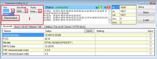
- Press button "Connect" to allow the Software connect with iConnector
- If connect successful, you will see Status shows "connected" as below picture
- If NOT, Status shows "disconnected"
3.3 Configuration parameters for iConnector
* There are many parameters of iConnector to be configured before using.
* However, most of the parameters were configured by the manufacturer.
* Customer will only need to configure some parameters like: APN, Username, password for Cellular iConnector, or other parameters.
* Please refer below sections to configure the parameter you want.
3.3.1 Configure the SIM card information for Cellular iConnector
- Cellular iConnector use the 2G, 3G or 4G connectivity to connect to IoT Server;
- It requires the Data SIM Card to be inserted into iConnector;
- Contact the Network Operator of Sim card to get the following information:
- APN:
- Username:
- Password:
- Click to the Tab 2G/3G on the Software;
3.3.1.1 How to configure the APN Name? Please follow these steps:
- Typing the APN in the Setting column, then click the check box "Sync" at that row to allow the data to be written to iConnector. Once written successfully, you will see the same data on the "Value" Column;
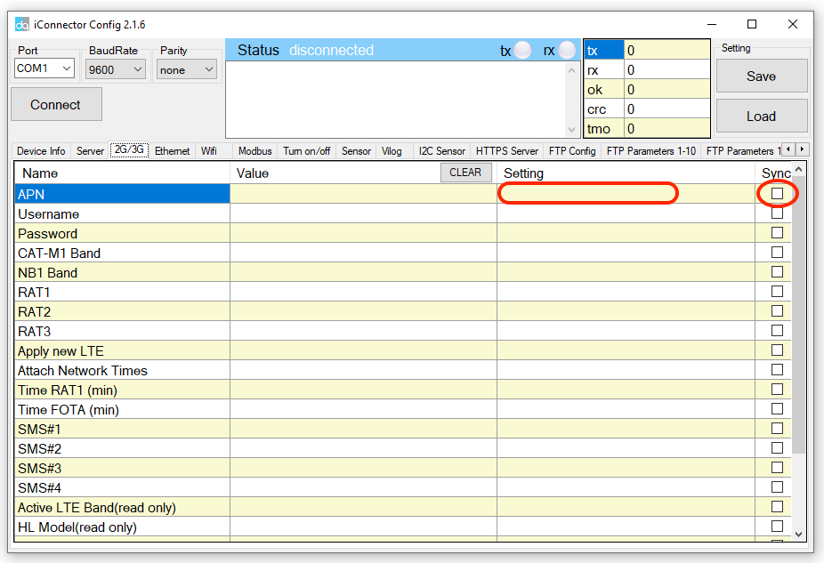
- If the data on Value column is different from the data on Setting column, that meant the data has not been written successfully to iConnector. Please check again:
- The connection from iConnector and Software is still connected or not?
- Then click the box "Sync" again.
Repeat these steps to configure other parameters: User name and Password.
3.3.1.2 How to check the iConnector was configured successfully and connected to Globiots Server?
- After configure successfully the SIM card information, the iConnector will connect to Globiots server automatically;
- The LED Network will be turn ON;
- Using the provided account of Globiots server, log in to the Globiots system to check the status of iConnector;
+ If connected, the icon will be Blue color;
+ If not connected, the icon is still Grey color; - If waiting for 5-10 minutes, the iConnector is still not connecting to Globiots server, please check the followings:
+ SIM card is contract with data plan?
+ The Network operator support the Frequency bands of iConnector? Please check the frequency band of iConnector in this link:
+ Make sure information APN, Username and Password is all correct?
+ Make sure the configuration is all correct with these values? Please check carefully each leter, a space letter at the end can cause the problem!
=====END=====
IV. Insert SIM Card for Cellular iConnector
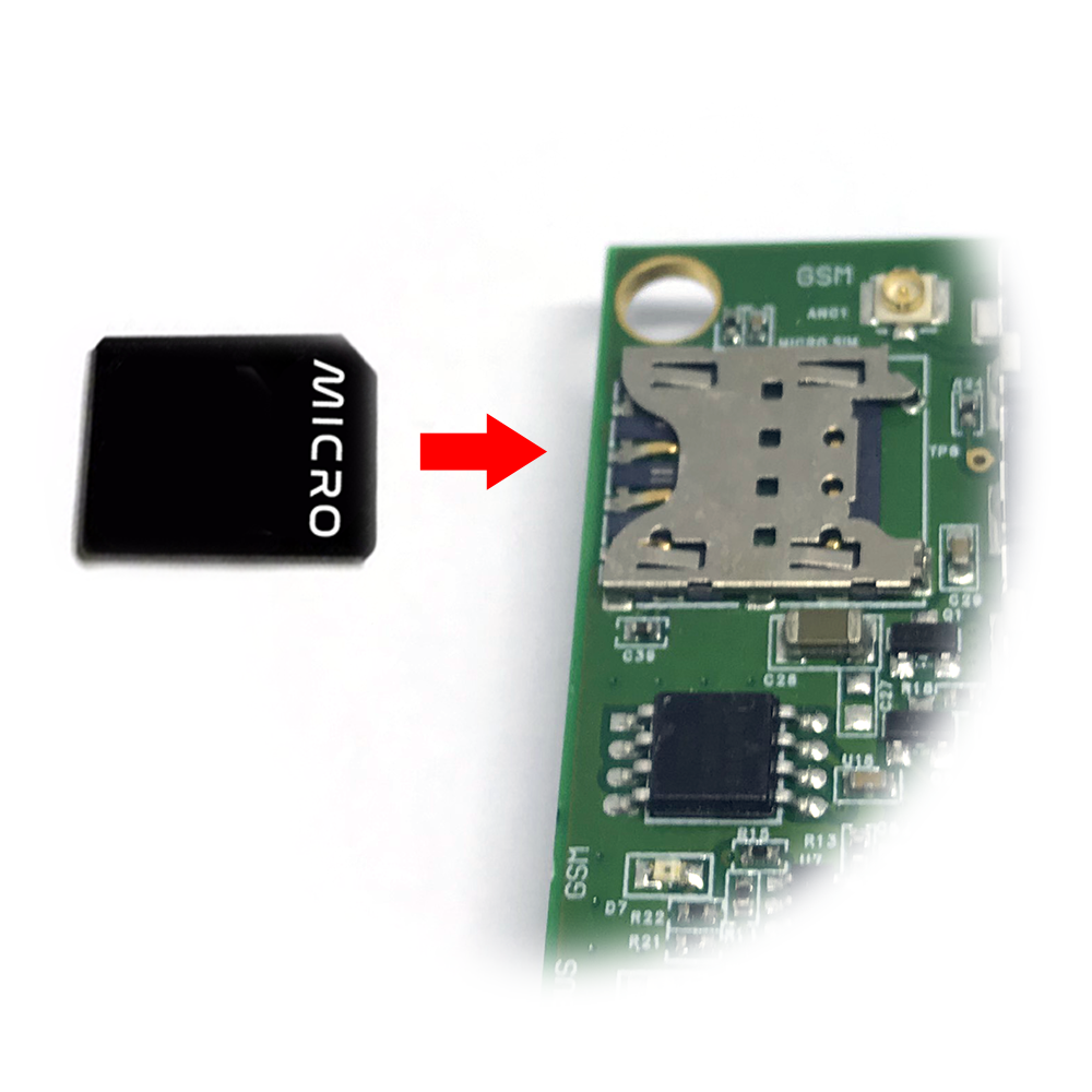
Steps to insert SIM card:
Step 1: Remove the housing
- Using L hex key to unscrew M4 screws at the side of the housing and carefully pull out the top plastic housing in the vertical direction
Step 2: Insert the SIM Card into the iConnector,
Please take note the direction of the SIM Card
The Sim card must be MICRO-SIM type
When inserting the SIM card please disconnect the power supply to avoid damaging the device !
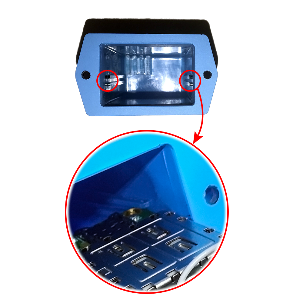
Step 3: Place back the housing and locking by L hex key
ATTENTION:
When reinstalling the cover, pay attention to put the PCB edge into the middle slot of the box inside as shown below)
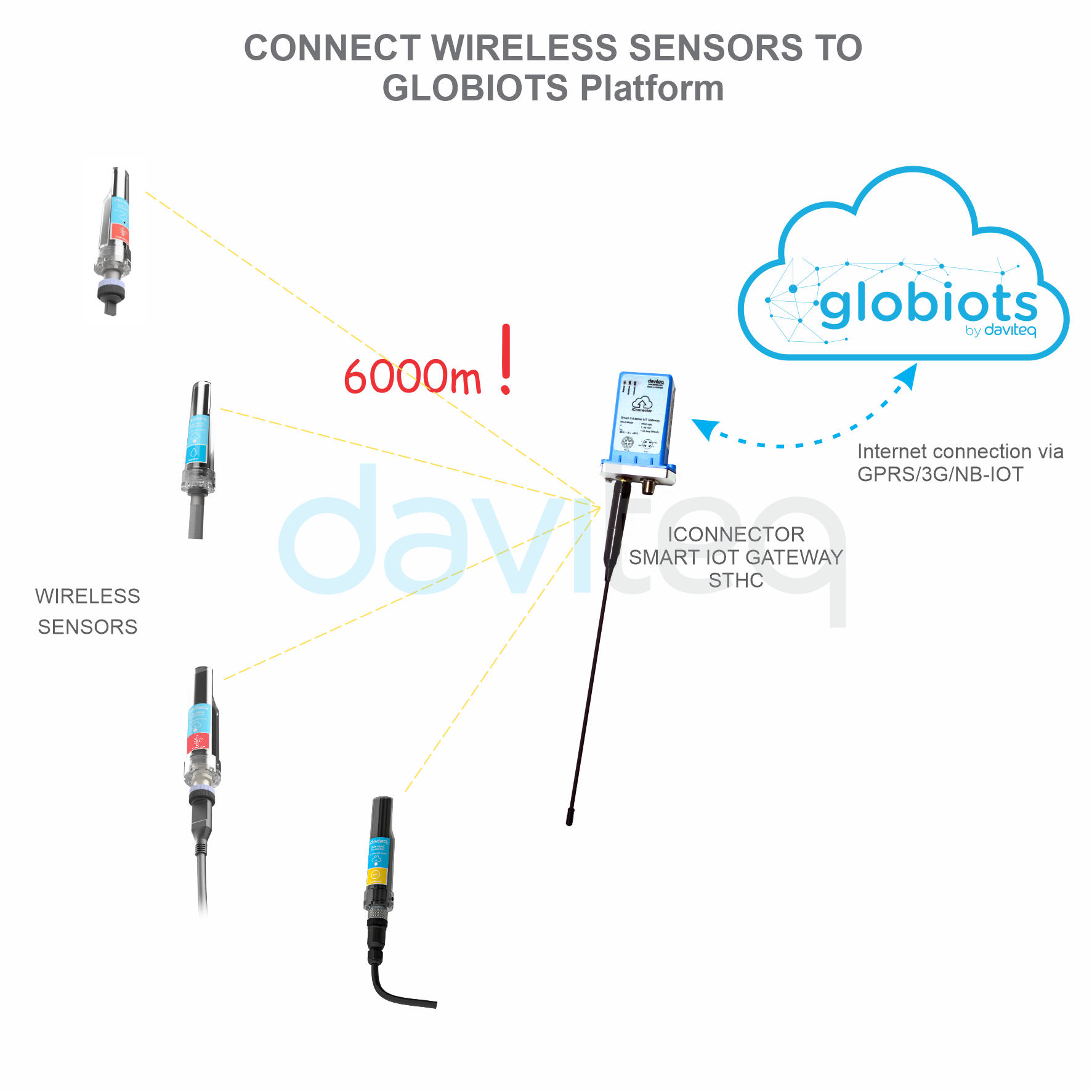
V. Installation iConnector STHC
5.1 Example application
iConnector is used widely in many applications for Smart Factory, Smart Facility/Building, Smart City, Smart Agriculture...
Please refer more information at: https://www.daviteq.com/ung-dung2/
5.2 Installation location
Depend on what kind of iConnector, the location of installation will be considered carefully.
5.2.1 if the iConnector has built-in Sub-GHz Wireless Co-ordinator or Wireless Bridge:
To maximize the distance of transmission between Sub-GHz wireless sensor and iConnector, the ideal condition is Line-of-sight (LOS) between the Wireless sensor and iConnector. In real life, there may be no LOS condition. However, the Wireless sensor still communicates with iConnector, but the distance will be reduced significantly.
- The antenna of Sub-GHz Wireless Co-ordinator of Wireless Bridge must be placed above ground as high as possible, not lower than 2m. We recommend the minimum is 4m;
- It's better to place the antenna outdoor, on top of the roof of building, house, warehouse...;
- It's not good if the antenna is place indoor but the wireless sensor is outdoor;
- Only when all the wireless sensors are indoor, then you can place the antenna of wireless co-ordinator indoor, too;
ATTENTION:
DO NOT install the Wireless sensor or its antenna inside a completed metallic box or housing, because the RF signal can not pass through the metallic wall. The housing is made from Non-metallic materials like plastic, glass, wood, leather, concrete, cement…is acceptable.
5.2.2 if the iConnector has Cellular connectivity like 2G, 3G or 4G:
- We highly recommend to install the iConnector outdoor or outside of the cabinet so that it can have strong signal of cellular;
- Do not put iConnector inside a metallic box as the cellular can not go thru the metal sheets;
- Incase the iConnector must be place inside a box for better protection, please use the box with plastic materials like ABS, ASA, Polycarbonate, Fiber Glass...
5.2.3 if the iConnector has WiFi connectivity:
- We highly recommend to install the iConnector at the place has strong coverage of WiFi signal;
- Do not put iConnector inside a metallic box as the WiFi signal can not go thru the metal sheets;
- Incase the iConnector must be place inside a box for better protection, please use the box with plastic materials like ABS, ASA, Polycarbonate, Fiber Glass...
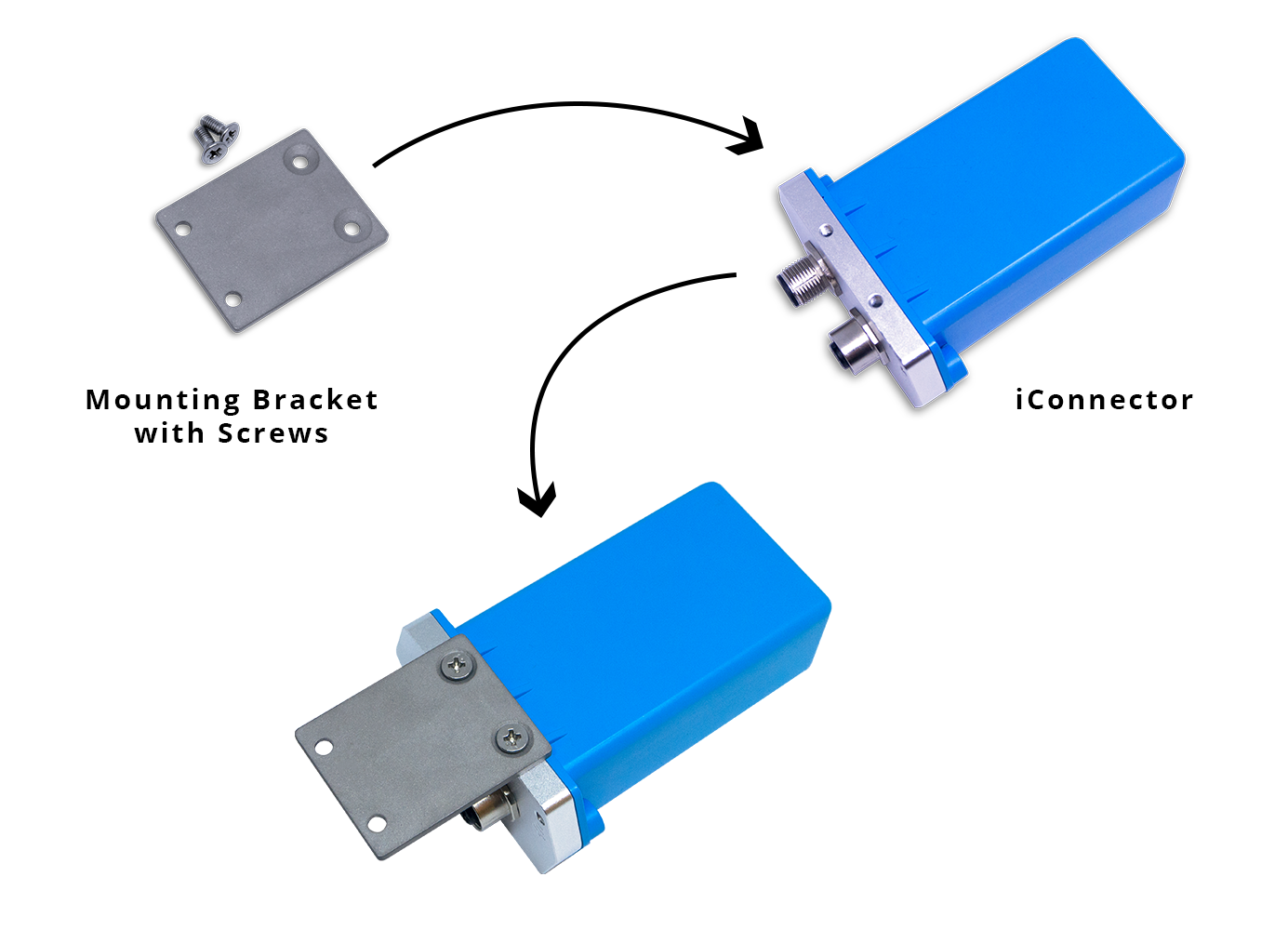
5.3 Mounting bracket for installation
5.3.1 iConnector with blue housing:
- The mounting bracket is made from hard metallic material. Following to these steps as the below picture
5.3.2 iConnector with White housing:
- There are 02 holes for screwing at the left and right of housing.
- These holes are covered by the cover.
- Open the cover, you can access the hole for screwing.
- Using screw with size 4mm diameter maximum.

VI. How to add iConnector STHC to Globiots Server System?
VII. Modbus Configuration for iConnector STHC on Globiots
VIII. Parameter Configuration for iConnector STHC on Globiots
IX. Alarm & Event Configuration for iConnector STHC on Glbiots
X. Configuring special functions of iConnector on Globiots
XI. Troubleshooting iConnector and Globiots
| No. | Phenomena | Reason | Solutions |
| 1 | Cannot read modbus |
|
|
| 2 |
Failed to add auto sensor (iConnector integrated Co-ordinator version) |
|
|
| 3 | Read modbus normal health values but read the data of the node, all are 0 |
|
|
| 4 | The node's data has no data of prm1 and prm2 |
|
|
| 5 | Status led of iConnector doesn’t light |
|
|
| 6 | Mobus led of iConnector doesn’t light |
|
|
| 7 | Network led of iConnector doesn’t light |
|
|
Manual of STHC-ISGWET-WS433-CL-04 | FW8
I.QUICK GUIDE (Ở 1 page riêng trong chapter)
1.1 Introduction
1.1.1 Introduction: có gateway/controller/datalogger/ modbus converter
1.1.2 System architecture
1.1.3 System components
1.1.4 How to setup the system
1.2 Application note
1.3 iConnector communication
1.3.1 Slave device communication: wired RS485 modbus RTU, wireless WS433
1.3.2 Host communication
Communication with Globiots platform=> detail in quick test
Real time data, logged data, event data, alarm data: limit bao nhiêu parameter, limit log cycle, limit lưu event và alarm N ngày
Communication with Modbus TCP/IP device=> detail in quick test
Communication with http/https server=> detail in quick test
Real time data, logged data, event data, alarm data: limit bao nhiêu parameter, limit log cycle, limit lưu event và alarm N ngày
1.4 Default Configuration
Đưa ra 1 số default về modbus config, server connection: host, port, ...về Daviteq globiots, default wifi: lấy thông tin từ bảng modbus, trình bày dạng bảng (No., Configuration Name, Data type, default value...
Trình bày về spec nguồn cấp, wiring nguồn cấp
Steps: Add to Globiots (link đến mục 1.10), select memap Standard => Import parameter health & bộ thu của 1 node, add modbus para, add modbus command (for 1 parameter)=> check value on memap tab => Wiring 1 modbus device (nếu dùng thêm modbus device) (optional) , wiring nguồn cấp/dùng adapter & pair 1 cảm biến (optional)=> power up, sych=> check online=> check value on memap tab
Note: memmap standard sẽ có thông tin của health, bộ thu node 1, parameter của 1 thiết bị modbus (địa chỉ 2000) và modbus status tại địa chỉ 2004
1.8 Installation and wiring
1.8.2 Installation and wiring for wired slave device
18.3 Installation and wiring for wireless sensor
18.4 Installation and wiring for host Modbus TCP/IP
Link của file iConnector memory map
1.10.1 How to connect device to Globiots platform
1.10.2 How to connect device to http server
1.10.3 How to connect device to Modbus TCP/IP server (only for ...with Ethernet connection)
II. MAINTENANCE (Ở 1 page riêng trong chapter)
2.1 Maintenance
2.2 Troubleshooting
III. ADVANCE GUIDE (Ở 1 page riêng trong chapter)
3.1 Principle of Operation:
Đọc modbus=> logged, realtime khi có yêu cầu, alarm , event=> gửi lên Globiots/https
Đọc modbus=> gửi lên Modbus TCP/IP server
3.2 Configuration
3.2.1 Cấu hình online từ Globiots
Cấu hình iConn, parameter, modbus, alarm, event dashboard, report
32.2 Cấu hình offline
Cấu hình modbus, cấu hình ip, wifi, connection, transparency... dùng phần mềm iConfig fw 8
IV.PRODUCT SPECIFICATIONS(Ở 1 page riêng trong chapter)
4.1 Specifications
V. WARRANTY & SUPPORT (Ở 1 page riêng trong chapter)
5.1 Warranty(Ở 1 page riêng trong chapter)
5.2 Support(Ở 1 page riêng trong chapter)