II. Principle of operation of iConnector STHC
2.1 General operation principles of iConnector
2.1.1 LED meaning
2.1.1.1 LED status
| Status | Meaning |
| Fixed ON | iConnector has been supplied with external power |
| Blinking (4 seconds blink 1 time) | Without external power, iConnector is using battery. |
| Blinking (2 seconds blink 1 time) | Low battery warning (Used for type D battery version) |
2.1.1.2 LED modbus
| Status | Meaning |
| Fixed ON | Modbus connected |
| Blinking (1 seconds blink 2 time) | Connection errors (wrong configuration of baudrate, noise, …) |
| OFF | No modbus connection |
2.1.1.3 LED network
| Status | Meaning |
| Fixed ON | Connecting with Globiots |
| Blinking (1s change state) | Initializing wifi generator, waiting for configuration via phone or modbus tool (For iConnector wifi) |
| OFF | No connection with Globiots |
2.1.2 Memory Map
|
Address |
Size (bytes) |
Memory type |
Read/Write |
Description |
|
0-0x1FFF |
8096 |
FLASH |
R/W |
Save active configuration, do not allow log, realtime. |
|
0x2000-0x22FF |
768 |
RAM |
R |
Save data read from modbus slaves. |
|
0x2300-0x24FF |
512 |
RAM |
R |
The intrinsic data of iConnector |
|
0x3000-0x30FF |
256 |
RAM |
R/W |
|
|
0x5000-0x50FF |
256 |
FLASH |
R/W |
|
|
0x6000-0x6FFF |
4096 |
RAM |
R |
Save data read from modbus slaves |
- Data address area: 0x2000-0x22FF (768 bytes), and 0x6000-0x6FFF (4096 bytes).
- Controller address area: 0x3000-0x30FF (256 bytes, without flash storage), and 0x5000-0x50FF (256 bytes, with flash storage).
Address area 0x5000-0x50FF
- 256 bytes;
- Save in flash (when power is lost, will keep the same value);
- Allows reading, and writing from Globiots;
- Allow log (realtime);
- Allows Modbus write to Slaves;
- It is not allowed to store data read from Modbus Slaves.
NOTE:
Flash recorded about 100,000 times will be damaged so do not use this area to contain the value is changed several times.
2.1.3 Logged data
- Up to 20 different log cycles;
- 320 log parameters maximum for all log cycles.
- Up to 120 log parameters per log cycle.
2.1.4 Modbus
- Support modbus RTU.
- Address slave 1… 247.
- It is not allowed to set address slave = 0.
- Baudrate 4800/9600/19200.
- Parity none / odd / even.
- Up to 100 modbus instructions.
- The address area for storing read data: 0x2000-0x22FF (768 bytes), and 0x6000-0x6FFF (4096 bytes).
- Controller address area: 0x3000-0x30FF (256 bytes, without flash storage), and 0x5000-0x50FF (256 bytes, with flash storage).
2.1.5 Realtime
- Read up to 200 parameters.
- If all parameters are float (4 bytes) then read up to 140 parameters.
- The fastest realtime sending frequency is 1 second.
2.1.6 Alarm
- Up to 28 alarms.
- Supported data types:
|
PrmType |
Description |
# Byte |
Range |
|
1 |
BYTE |
1 |
0 to 255 |
|
2 |
UINT16 |
2 |
0 to 65,535 |
|
3 |
UINT32 |
4 |
0 to 4,294,967,295 |
|
4 |
FLOAT |
4 |
-/+3.40282347 * (10^+38) |
|
5 |
INT16 |
2 |
-32,768 to 32,767 |
|
6 |
INT32 |
4 |
-2,147,483,648 to 2,147,483,647 |
2.1.7 Event
- The event table is 1024 bytes.
- The number of events depends on the short length of the event configured.
- Supported data types:
|
PrmType |
Description |
# Byte |
Range |
|
1 |
BYTE |
1 |
0 to 255 |
|
2 |
UINT16 |
2 |
0 to 65,535 |
|
3 |
UINT32 |
4 |
0 to 4,294,967,295 |
|
4 |
FLOAT |
4 |
-/+3.40282347 * (10^+38) |
|
5 |
INT16 |
2 |
-32,768 to 32,767 |
|
6 |
INT32 |
4 |
-2,147,483,648 to 2,147,483,647 |
2.1.8 Health data
- Every 15 seconds send health pack 1 time.
2.1.9 Relay
There are 2 relays:
- Relay control address 1: 0x3100.
- Relay control address 2: 0x3101.
2.2 iConnector Cellular
2.2.1 GSM signal quality
|
Value |
RSSI dBm |
Condition |
|
0-9 |
≤-113 to -95 |
Marginal |
|
10-14 |
-93 to -85 |
OK |
|
15-19 |
-83 to -75 |
Good |
|
20-31 |
-73 to ≥-51 |
Excellent |
|
99 |
|
not known or undetectable |
2.2.2 GSM status
|
Value |
Status |
|
0 |
Connect to the server: OK |
|
1 |
Connect to network operator: OK, the server is not connected yet |
|
2 |
Communicate with GSM modem with AT command: OK |
|
3 |
The GSM modem is starting |
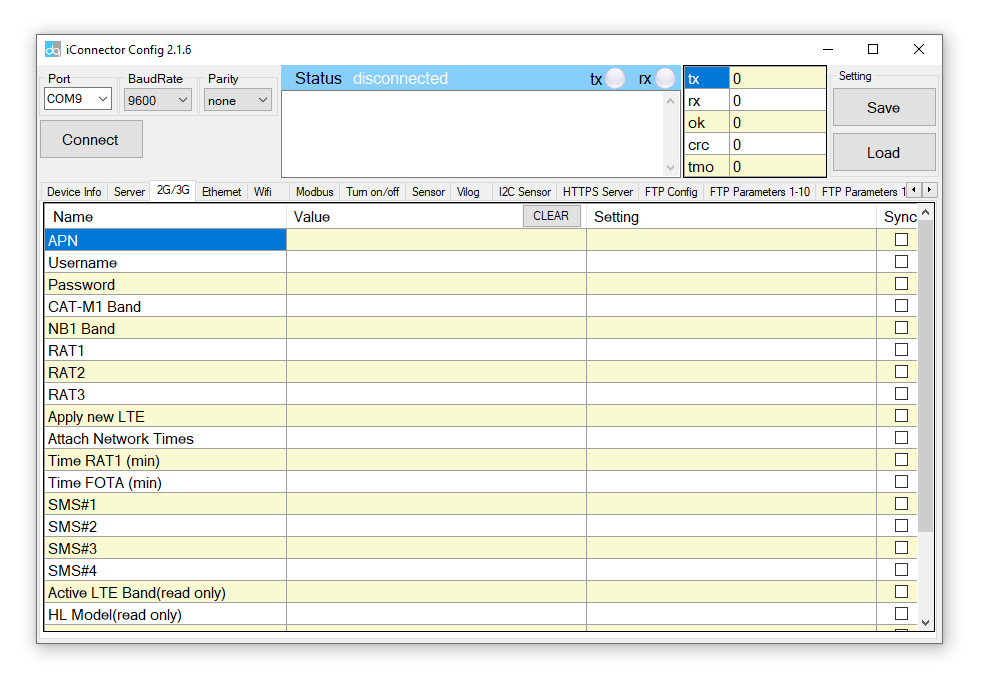
2.2.3 APN Configuration
- Use the iConnector Config Software to connect and configure iConnector
Refer to section 5 for more details about how to use Configuration Cable.
Refer to section 6 for more details about how to insert SIM Card.
Refer here for more details on how to add sensor to the iConnector integrated Co-ordinator.
- Open the 2G / 3G tab, then fill in the APN information of the SIM Card (APN, Username, Password,..) in Setting. Finally click Sync to configure
2.3 iConnector Ethernet
2.3.1 What is TCP/IP ?
2.3.2 Configure with iConnector Config software
Refer to section 5 for more details on how to use Configuration Cable
3.3.2.1 Ethernet tab
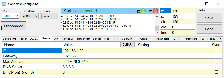
| Name | Description |
| IP | Static IP configuration for iConnector. Example: 192.168.1.30 |
| Gateway | Configure gateway |
| DNS Server | Configure DNS Server |
| DHCP |
0 (Off) / 1 (On) If DHCP = 0, it's mean Not using DHCP → Static IP |
3.3.2.2 Modbus-TCP-Server tab
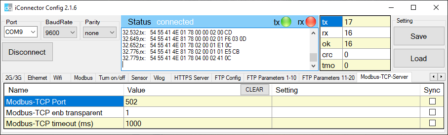
| Name | Description |
| Modbus-TCP Port | Configure the receiving port, for example 502 |
| Modbus-TCP enb transparent |
1 : To run transparent, interrupt modbus RTU poll. 0 : Run modbus RTU poll as normal iConnector, not transparent |
| Modbus-TCP timeout (ms) | Used for modbus TCP Server |
2.3.3 Description of transparent mode operation (Modbus-TCP enb transparent = 1)
Suppose we have: Static IP address: 192.168.1.30 | Port 502
1. iConnector is connected to the Modbus RTU with electric meters, devices, ... via RS485 port;
2. Software / device / PLC ... with Modbus TCP Client connected to iConnector (role as TCP Server) at Static IP address 192.168.1.30 | Port 502 in internal network;
3. TCP Client sends command to iConnector;
4. iConnector transfers commands from Modbus TCP to RTU and sends to devices and clocks via RS485 port;
5. iConnector waits for the devices to respond;
6. iConnector transfers the response from the RTU to the Modbus TCP and then sends it back to the TCP Client;
7. TCP Client actively closes the connection if it no longer sends command to iConnector.
2.3.4 Run Modbus RTU as normal iConnector (Modbus-TCP enb transparent = 0)
3.3.4.1 TCP Client connects to iConnector via internet
1. iConnector needs static IP configuration, For example: IP 192.168.1.30 | Port 502
2. The external internet network must also have a static IP, Example: IP 118.69.111.101
3. Network administrator must implement NAT port 502, TCP to IP of iConnector
4. At that time, TCP Client will connect to IP address 118.69.111.101 | Port 502
3.3.4.2 TCP Client read/write parameters on the iConnector memmap
iConnector supports command 3 (0x03) for read, command 16 (0x10) for writing.
The Unit Identifier is 31 (0x1F) to read and write memmap iConnector, not 31 will make devices transparent read and write via RS485.
These commands are changed to match the address of iConnector (address in bytes but not in registers like modbus).
1. Command 3:
Modbus TCP is:
0001 0000 0006 1F 03 006B 0003
- 0001: Transaction Identifier
- 0000: Protocol Identifier
- 0006: Message Length (6 bytes to follow)
- 1F: The Unit Identifier (31 = 1F hex)
- 03: The Function Code (read Analog Output Holding Registers)
- 2000: The Data Address of the first register requested → This will be the address on the memmap
- 0003: The total number of registers requested. (read 3 registers 40108 to 40110) →This number 3 will be 3 bytes, not 3 registers anymore.
At that time iConnector will respond to data of 3 bytes, not 6 bytes
2. Command 16:
Modbus TCP is:
0002 0000 0009 1F 10 3000 0002 04 000A
- 0002: : Transaction Identifier
- 0000: Protocol Identifier
- 0009: Message Length (6 bytes to follow)
- 1F: The Unit Identifier (31 = 1F hex)
- 10: The Function Code 16 (Write Function)
- 3000: The Data Address of the first register requested → This will be the address on the memmap
- 0002: The number of registers to write → This is the length to write is 2 bytes, not 2 more registers.
- 04: The number of data bytes to follow
- 000A: The value to write to register → data 2 bytes need to write
2.4 iConnector Wifi
2.4.1 Configure using the iConfig app on the phone
Please refer to how to configure using iConfig app with the following link:
iConfig Mobile app for Android
2.4.2 Configure using the Configuration Cable
Refer to III. Offline configuration for iConnector for more details on how to use Configuration Cable
Step 1: Open the configuration tool and switch to the Wifi tab;
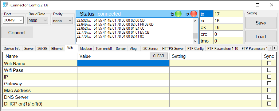
Step 2: Step 2: Configure the Wifi Name and Password that iConnector Wifi will connect to;
Step 3: Check the Network LED. If the LED is always on, the connection is successful.
2.4.3 Modbus-TCP-Server Configuration
Please refer to the Modbus-TCP-Server configuration section in section 4.3.