Tools and Documents
- List of Tools and Configuration Documents
- User Guide for Modbus Configuration Tool
- How to use Excel file Modbus Memmap of Co-ordinator
- Instructions for Upgrading the Firmware for Daviteq Sigfox Sensor
- Support for Flashing The Firmware in Daviteq Lorawan Sensor
List of Tools and Configuration Documents
1. Configuration Tool on PC:
1.1 Modbus Configuration Tool:
- Version 1.0: https://filerun.daviteq.com/wl/?id=J9cdBHxOUFhRvywyyQBu1n6zJmLhnA6u
- Version 1.2 (with Template): https://filerun.daviteq.com/wl/?id=RtuE0i9N8KNJ8fTVdHv4DcJEHdaDcetp
- Version 1.4: https://filerun.daviteq.com/wl/?id=qK0PGNbY1g1fuxTqbFW9SXtEvCw7bpc6
- Version 2.03: https://filerun.daviteq.com/wl/?id=yDOjE5d6kqFlGNVVlMdFg19Aad6aw0Hs
1.2 iConnector Configuration Tool:
- Version 2.1.4: https://filerun.daviteq.com/wl/?id=SsNWQvqmyVk3iuyM8Nwrl8EY8pOpgxQT
- Version 2.1.5: https://filerun.daviteq.com/wl/?id=s5QApxosVNZLbATxi0TtKVoJX4ms1PxD
1.3 Sigfox Tool:
- SigfoxFrame-2022.02.28: https://filerun.daviteq.com/wl/?id=Pg9BS32fTS5QElxLMVchNDeR4vgLJtVh
2. Configuration Documents:
2.1 Sub-GHz WS433 Wireless Sensor:
2.1.1 Modbus memmap:
- Template_WR433_V1.6: https://filerun.daviteq.com/wl/?id=YJjjobfLllV01rP9t8JxFf12564tF99r
- Template for WS433-AC: https://filerun.daviteq.com/wl/?id=s5QApxosVNZLbATxi0TtKVoJX4ms1PxD
- Modbus Memmap of WS433-CL-FW_V1.9 for WS433-FW_V5.xx_200314: https://filerun.daviteq.com/wl/?id=fnepmO8uKmnp7P5R90Iu4osu8DcZlzjp
- Modbus Memmap of WS433-CL-FW_V1.9 for WS433-FW_V5.xx_200717: https://filerun.daviteq.com/wl/?id=AYGwq8IvJjvV6co0R1RIg4B8YrqHi6go
- Modbus Memmap of WS433-CL-FW_V1.9 for WS433-FW_V5.xx_200825: https://filerun.daviteq.com/wl/?id=c6GtCgBuFowZthBDM0KVsCxsPyZ83U68
- Modbus Memmap of WS433-CL newest version: https://filerun.daviteq.com/wl/?id=BKEaUzdArkoc0Hc7nfpRShdPVToVrqQZ
2.1.2 WS433 Wireless sensor:
- WR433-AP-EN-12-Template_WR433_ULA_V1.0.csv: https://filerun.daviteq.com/wl/?id=BOfpTe7woBFbNULuHqsLhlJI4GmZ33fi
- WR433-AP-EN-08_Template_WR433_V2.0.csv: https://filerun.daviteq.com/wl/?id=hgrjOg3wwvyrvAZ54p8iZiFpDyXTcnec
- Excel file calculate a and b (calc_ab.xlsx): https://filerun.daviteq.com/wl/?id=qTEXAavKl1dSbnkbUgSAQXdK2jEtr1qA
- CONFIGURATION TEMPLATE FILE FOR RD26.csv: https://filerun.daviteq.com/wl/?id=1ZNVkHMxCTj0fxWZXrwtWbrr2MYfSc3S
- WR433-AP-EN-11-Template_WR433_V1A_V1.0.csv: https://filerun.daviteq.com/wl/?id=ItFaeQgtCmXN98J7GaPdeZvKK5eS1Dd1
- Configuration Template File For Sigfox WSSFC-AI FW1.9.3: https://filerun.daviteq.com/wl/?id=nZTEYrkbpTqPNXnRZeUwkXpQnMFLmuAQ
- WSSFC-AP-EN-01-Template_WSSFC_AG_V1.0.csv: https://filerun.daviteq.com/wl/?id=kQ8a6XqmkfOed2cmMT8y11ZITxxBz6Tu
- NH3 Sensor-2021.10.30-Template-V1.2.csv: https://filerun.daviteq.com/wl/?id=R0KxkPxLCDikuPEyu3uM8XhdX8kjcQXr
- CONFIGURATION TEMPLATE FILE FOR SIGFOX WSSFC-V1A.csv: https://filerun.daviteq.com/wl/?id=xjsWFgfbOwfKls3WKAyqLDUrziIbwgc4
- CONFIGURATION TEMPLATE FILE FOR SIGFOX WSSFCEX-EVC FW1.9.3.csv: https://filerun.daviteq.com/wl/?id=qznJW83Ie9vVhDdITcN1bCKTfeXCiXke
-
CONFIGURATION TEMPLATE FILE FOR SIGFOX WSSFCEX-PPS FW1.9.3.csv: https://filerun.daviteq.com/wl/?id=fnyrJTMBkHZMaYmdkuhSUhvXtzqdbkHg
2.4 LoRaWAN sensor:
- CONFIGURATION TEMPLATE FILE FOR WSLRW-SMT-ULB-ULC FW1.0.csv: https://filerun.daviteq.com/wl/?id=y266zlX9PnjB46LZt5nupMQKZPc6j3dW
- CONFIGURATION TEMPLATE FILE FOR LORAWAN SENSOR FW1.0.csv : https://filerun.daviteq.com/wl/?id=OrusBxds6ZCYB64paNKp6XWTtNsi84Kh
2.3 Modbus RTU sensor:
- CONFIGURATION TEMPLATE FILE FOR MBRTU-PODO V1.0.csv: https://filerun.daviteq.com/wl/?id=ijcWTpXwzz0IiAsfO7rInrXQ1LeBdwJu
-
CONFIGURATION TEMPLATE FILE FOR MBRTU-I2C.csv: https://filerun.daviteq.com/wl/?id=pTlOMMJNK1wF9JBszKybiupqoeWapD58
User Guide for Modbus Configuration Tool
| AUG-2020 |
Daviteq Modbus Configuration Tool
| HW Ver. | Release Date |
| 1.0 | NOV-2019 |
| 1.4 |
OCT-2020 |
| 2.03 |
DEC-2021 |
1. Install Tool
1.1 Download Tool
Install the Modbus Configuration Software in the link below
https://filerun.daviteq.com/wl/?id=yDOjE5d6kqFlGNVVlMdFg19Aad6aw0Hs
2.2 Running Tool
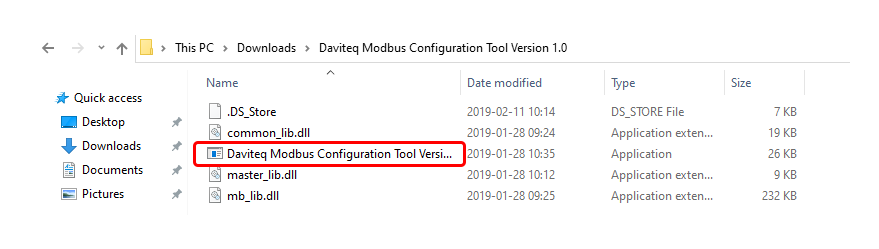
After unzip file, open the folder and run the application (Daviteq Modbus Configuration Tool Version).
2. Configuration
2.1 Connection
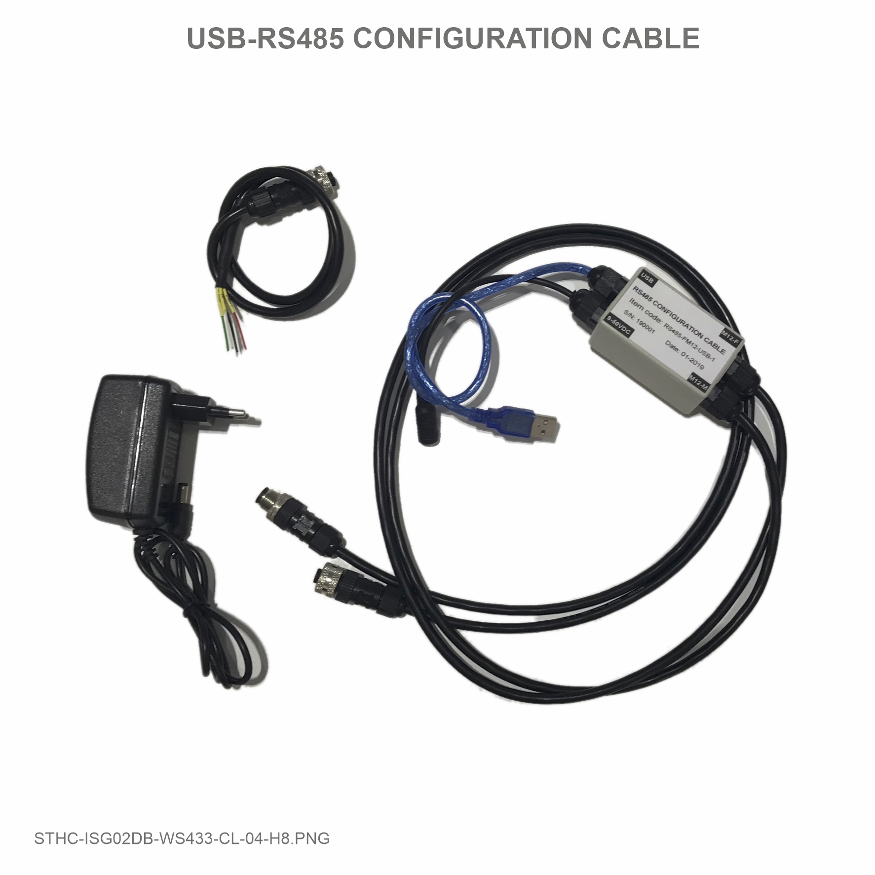
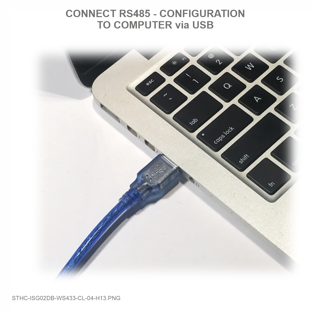
Step 1: Connect the configuration cable to the PC and Modbus device.
 |
 |
 |
 |
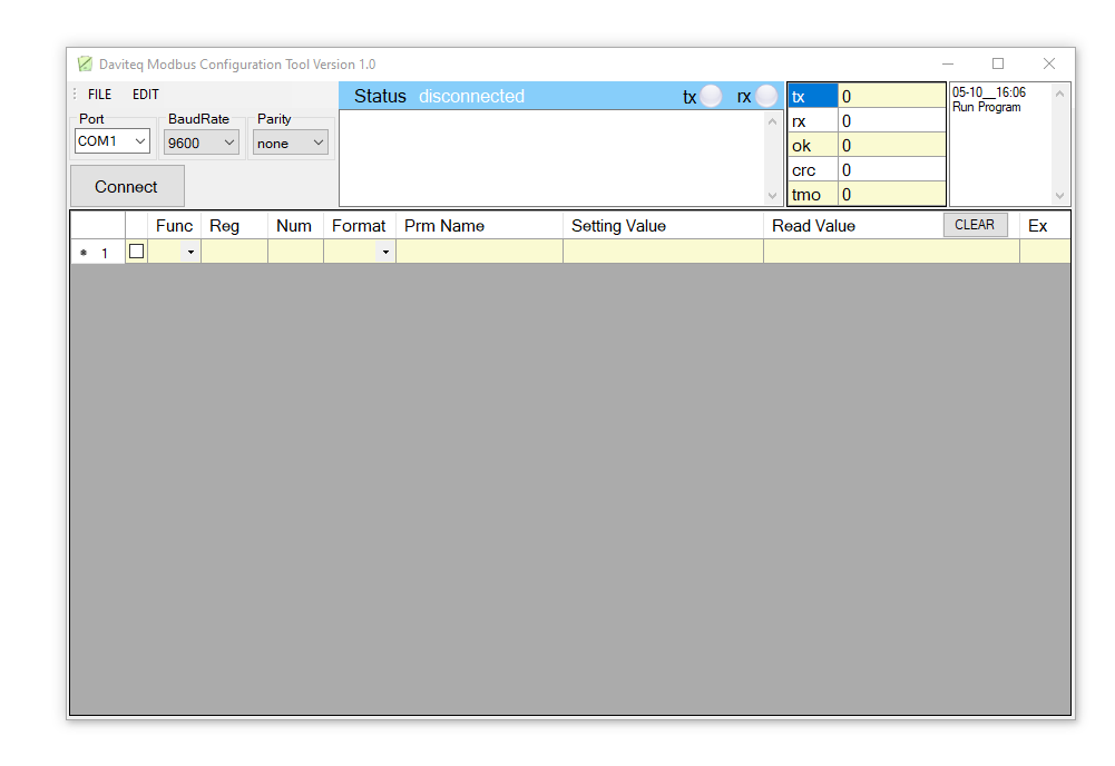
Step 2: Choose COM Port (the Port which is USB cable plugged in). Set the BaudRate: 9600, Parity: none
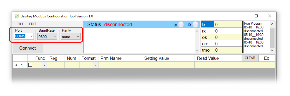
If you don't see any COM port in the list, please download the following driver and install
Modbus Configuration Cable COM port driver for PC
How to install driver
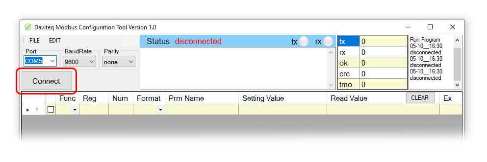
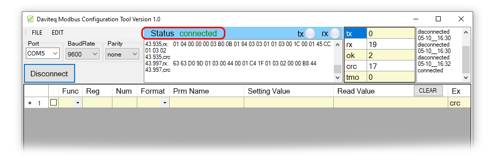
Step 3: Click “ Connect “ untill the Status displays “disconnected” to “connected“. It means the Modbus device is being connected with computer;
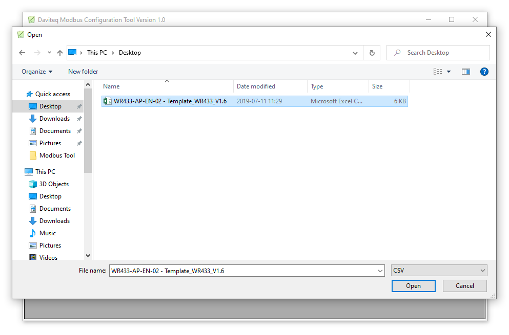
Step 4: Import the configuration file for Modbus Device by importing the csv file: Go to MENU: FILE / Import New /
Then select the template file.
Example: We import template file of Wireless Co-ordinator WR433-AP-EN-02 - Template_WR433_V1.6.csv
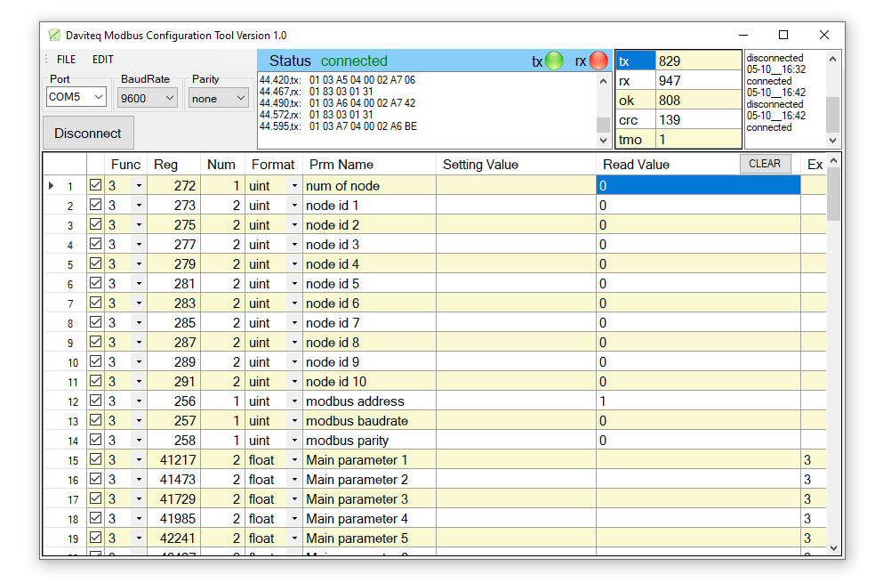
There are 3 Function:
- Function 3: Read holding registers
- Function 4: Read input registers
- Function 16: Preset Multiple registers
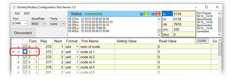
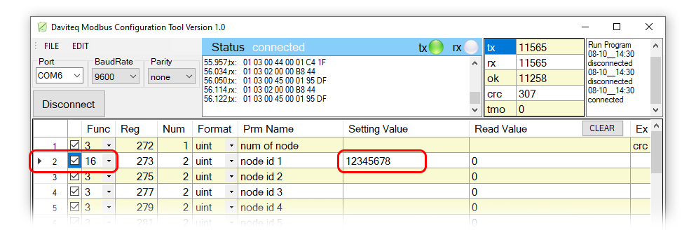
2.1 Write Value into Modbus Device with Function 16
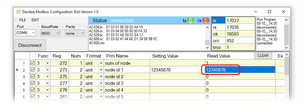
Example: We change the value Node id 1 from 0 to 12345678 using Func 16.
Step 1: Uncheck Func 3, then Click on the arrow and change Func from 3 to 16;
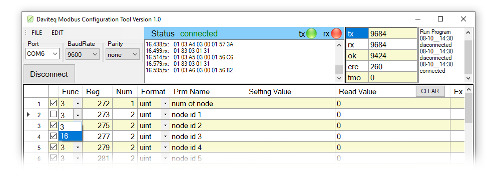
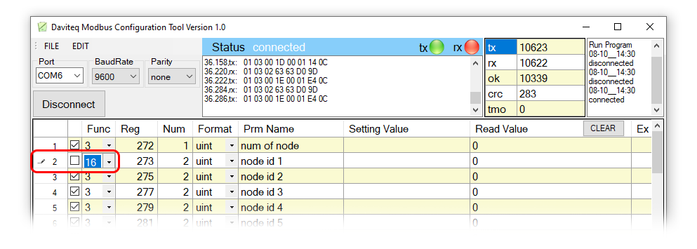
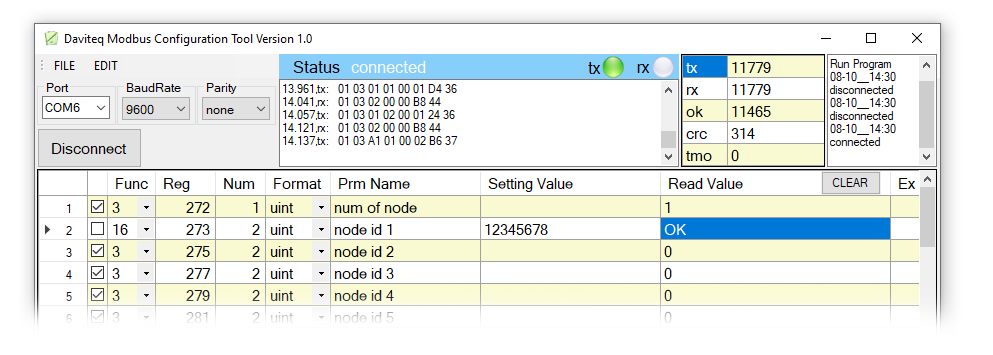
Step 2: Type in Setting Value the Node id 1, then check the Func 16 box.
if Read Value show OK which mean it's wrote successful.
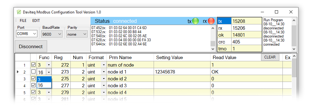
2.1 Read Value from Modbus Device with Function 3
After writing the value, we will check the value entered with Func 3. Func 3 is used to read holding registers.
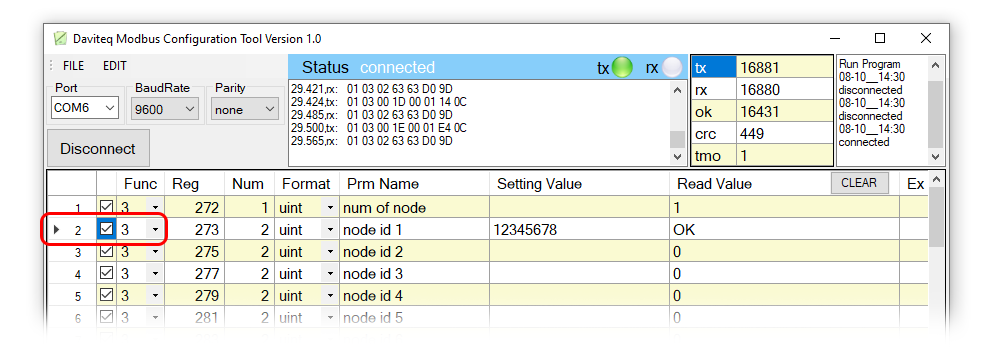
Step 1: Click on the arrow and change Func from 16 to 3.
Step 2: Check the box of Func 3. If it shows that the value in Read Value is the same as the value entered, it means that the data entered was successful.
3. Troubleshooting
| No. | Phenomena | Reason | Solutions |
| 1 | Cannot connect to software |
|
|
| 2 | COM port does not appear in the select list |
|
|
| 3 | Cannot see any register on software | The template file has not been imported | Go to File/Import New to import the template file |
| 4 | See registers that do not match the memmap table of the device rs485 or sensor is configuring | The template file imported incorrectly | Go to the correct manual page of the product configuring and download the template file, then import the template file into the software |
4. Support contacts
|
Manufacturer
Daviteq Technologies Inc Email: info@daviteq.com | www.daviteq.com
|
Distributor in Australia and New Zealand
Templogger Pty Ltd Tel: 1800 LOGGER Email: contact@templogger.net |

How to use Excel file Modbus Memmap of Co-ordinator
| FEB-2022 |
1. Introduce
When we add a sensor to the Co-ordinator WS433-CL or iConnector integrated Co-ordinator, the added sensor will be in the corresponding Modbus area in the Co-ordinator. The sensor's Modbus area can be monitored with our excel file. You can then read the data from the respective Modbus addresses using the PLC,HMI,... or use our Modbus Configuration Tool to view the values from the sensor.
1.1 Download Excel file
Download the Modbus Memmap Excel file in the link below:
https://filerun.daviteq.com/wl/?id=BKEaUzdArkoc0Hc7nfpRShdPVToVrqQZ
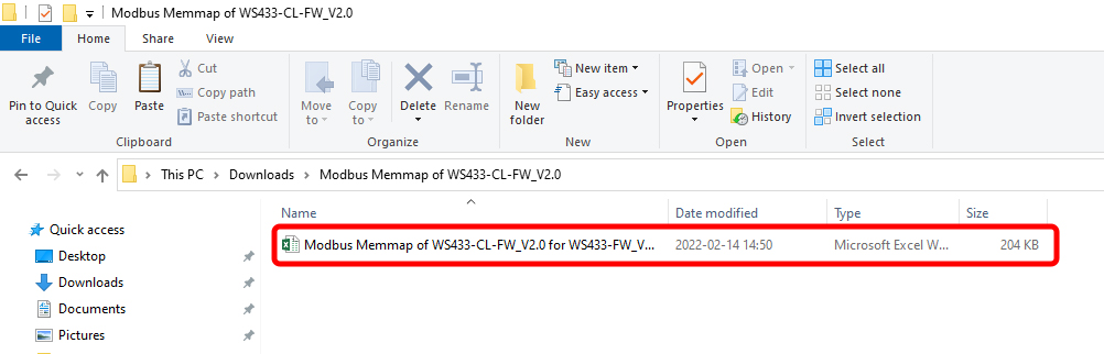
1.2 Excel file
After unzip file, open the excel file (Modbus Memmap of WS433-CL-FW_Vxx)
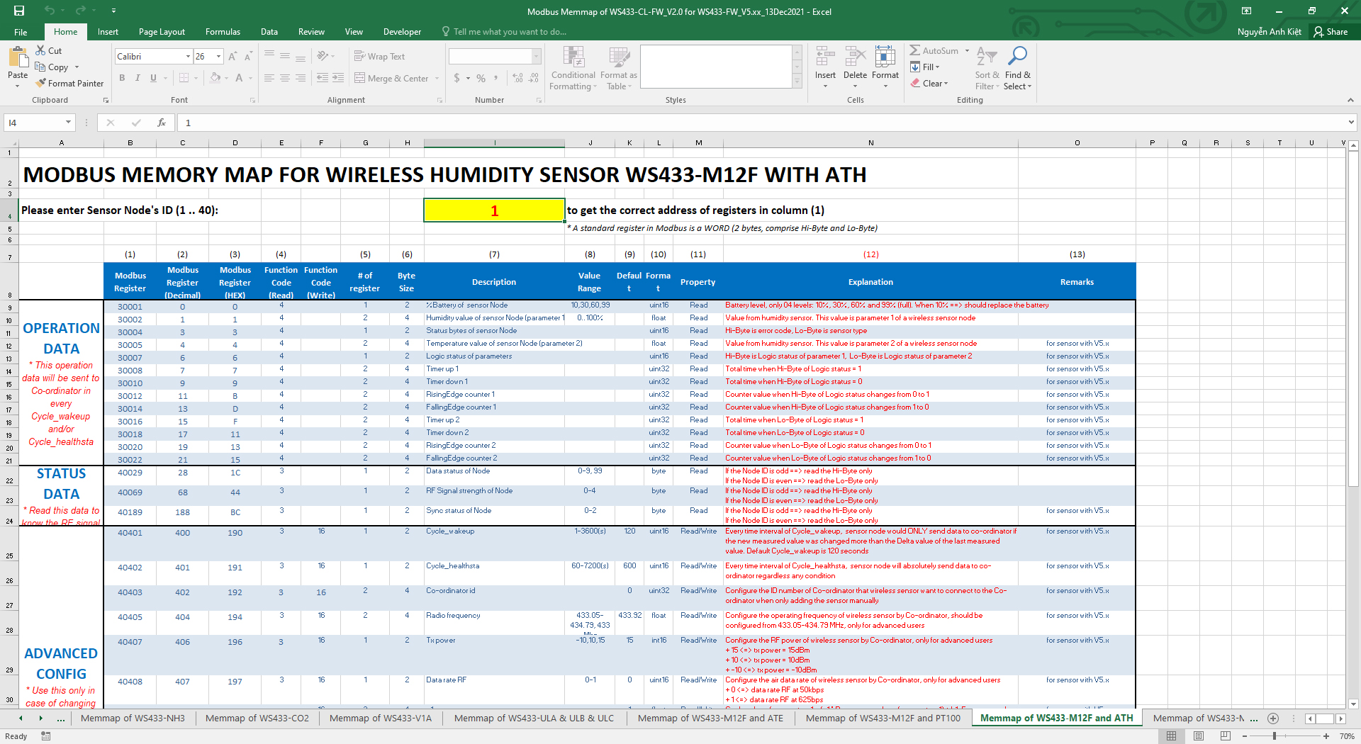
2. How to use
- We will choose the sheet that matches the sensor in use
Example: Choosing WS433-M12F and ATH sheet for WS433-M12F-ATH or WS433-ATH

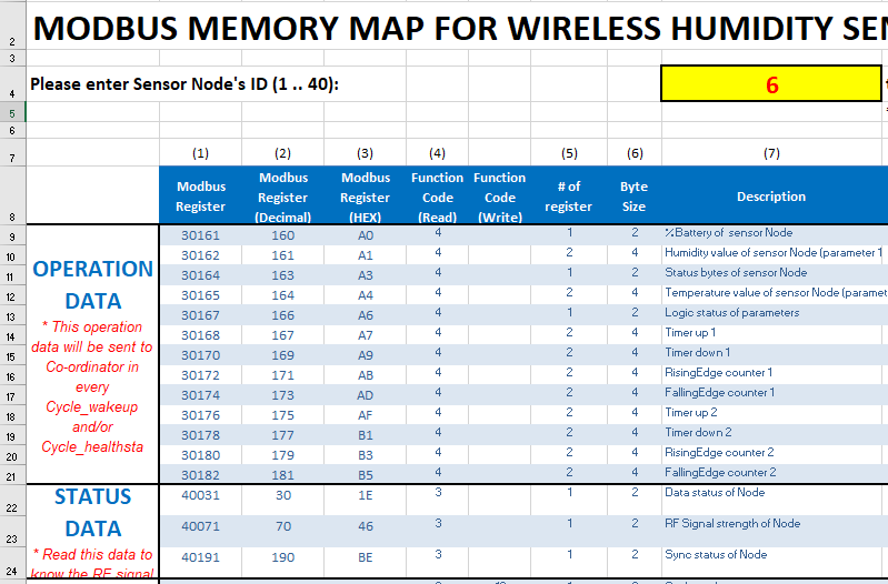
- We write in the number where the sensor has been added to the Co-ordinator in the yellow frame to get the register address.
Example 1: WS433-ATH is the first sensor to be added, so it has a position of 1
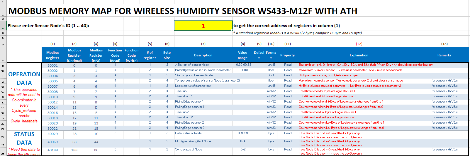
Example 2: WS433-ATH is the third sensor to be added, so it has a position of 3
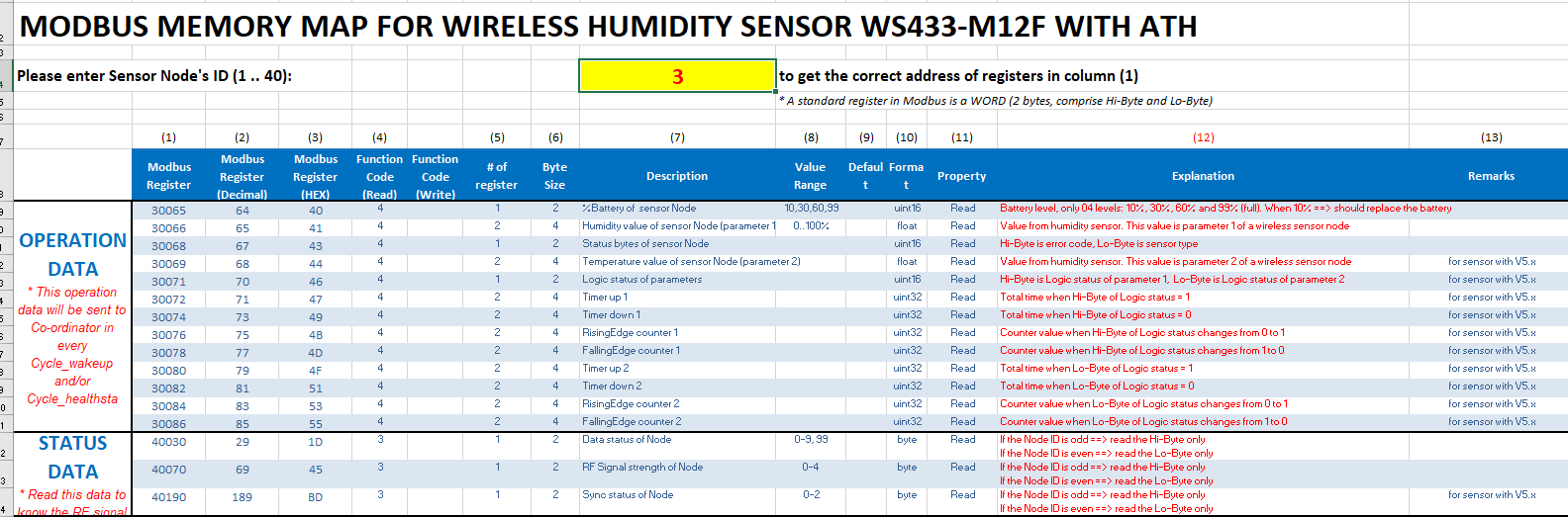
- We will see the parameters in the address column will change

3. Troubleshooting
| No. | Phenomena | Reason | Solutions |
| 1 | Cannot type into yellow frame of excel file | Edit mode is not open yet | Click Enable Editing to edit the number in yellow frame |
| 2 | No suitable sensor found |
Old memmap or other modified sensor name |
|
4. Support contacts
|
Manufacturer
Daviteq Technologies Inc Email: info@daviteq.com | www.daviteq.com
|
Instructions for Upgrading the Firmware for Daviteq Sigfox Sensor
1. Preparation
1.1 Prepare a ST-LINK V2 cable that connect between PC and the sensor.
1.2 Save the updated firmware file (.hex) to the PC for flashing to the sensor.
1.3 Save the ID & PAC file (.bin) to the PC for configuring the sensors.
2. Download and install the software "STM32 ST-LINK Utility".
The software can be downloaded from internet via the link: https://www.st.com/en/development-tools/stsw-link004.html
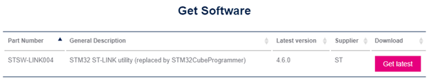
Figure 1. Getting the software from the website.
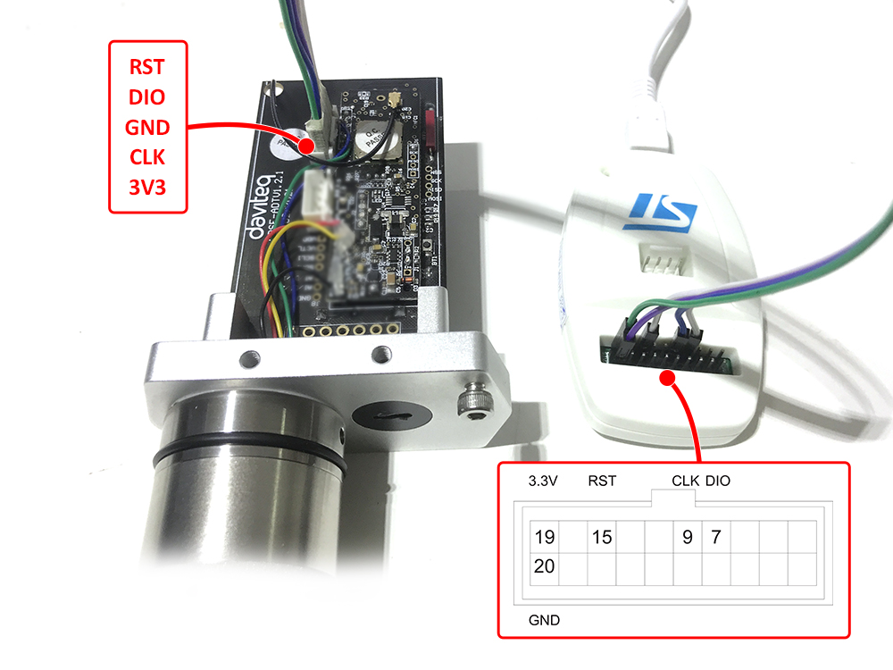
3. Set up the hardware
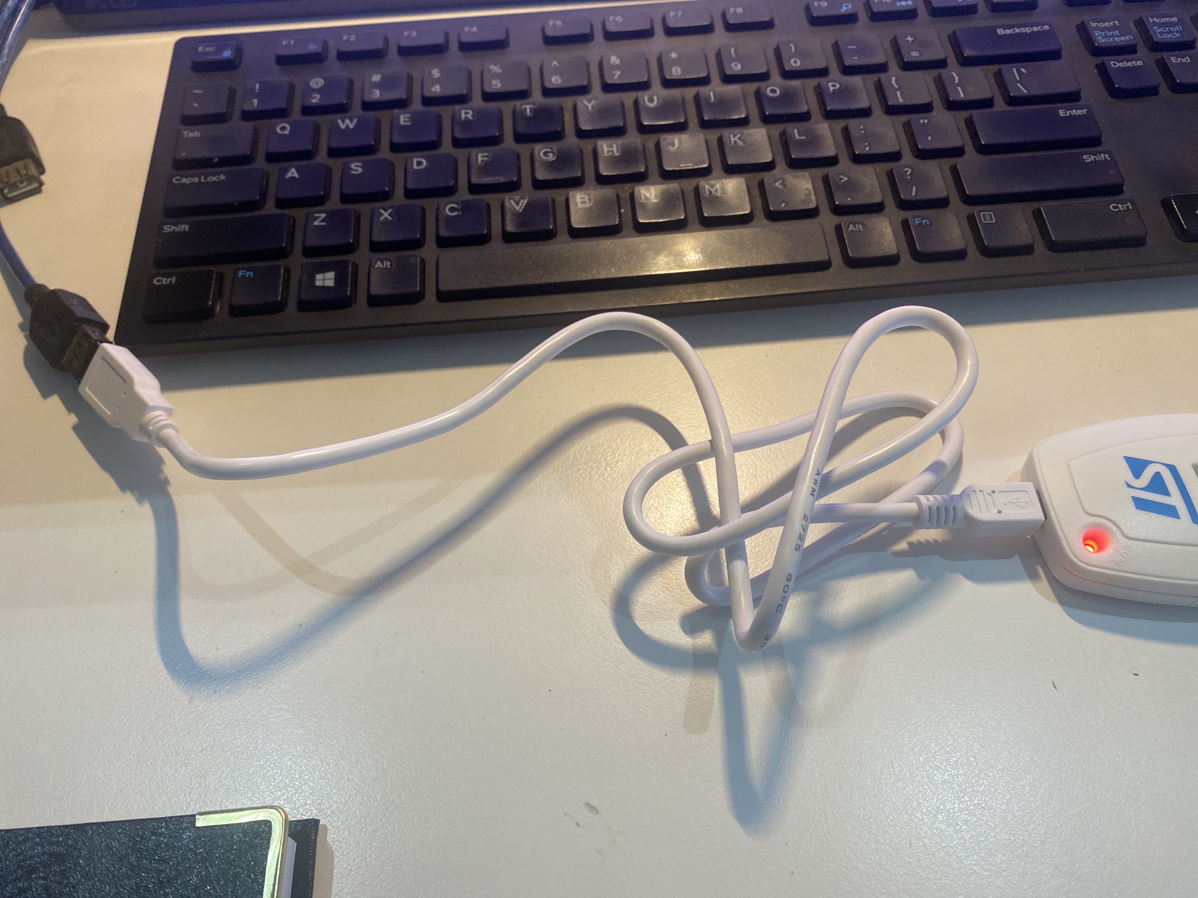
Connect the USB port of the ST-LINK V2 to the PC. The other end should be plugged into the PRG port of the sensor.
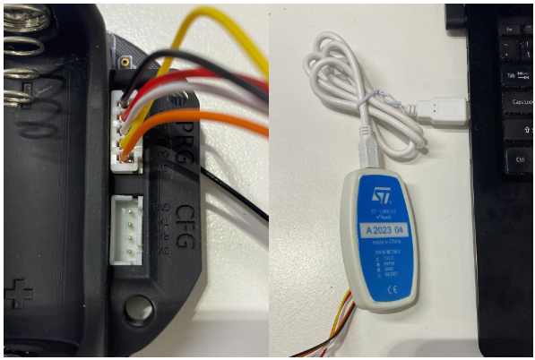
Figure 2. Hardware setup
4. Software configuration
4.1. Open the STM32 ST-LINK Utility software.
4.2 Target => Settings. Then, select "Connect Under Reset" and check "Enable debug in Low power mode" in Mode section =>OK
 |
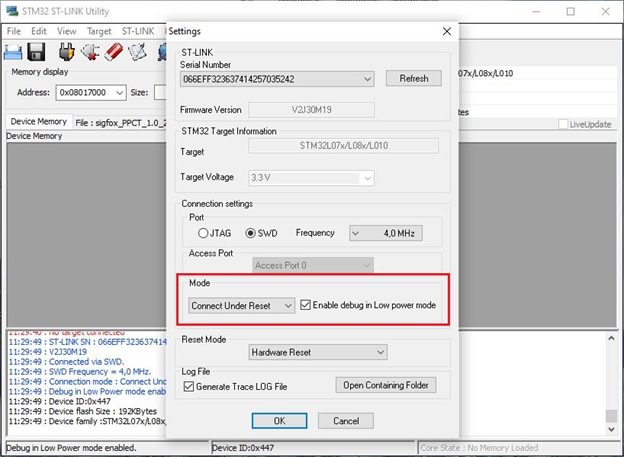 |
Figure 3. Software configuration
Make sure that the PC has a connection to the devices with the cable provided.
5. Loading firmwares.
5.1 Target -> Program & Verify...
5.2 File path => Browse => Choose firmware file (.hex)
|
|
|
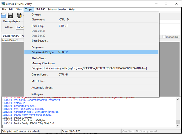
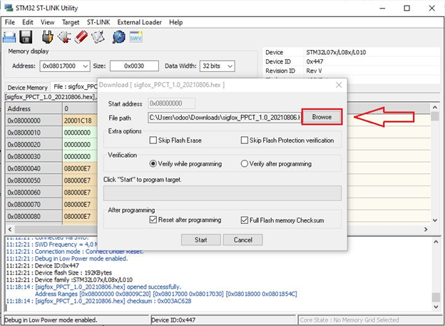
Figure 4. Import firmware file
5.3 Press Start to load the firmware to the sensor
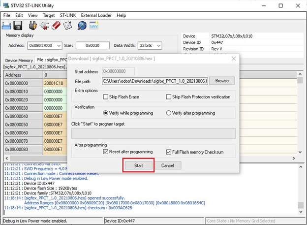
Figure 5. Loading firmware
When the firmware is successfully loaded, the software will display information with figure 6
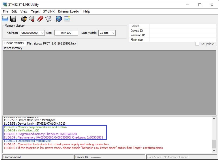
Figure 6. Successfully loading firmware
6. Loading ID and PAC.
After successfully loading the firmware in Step 5, you need to reload the ID&PAC for the sensor. Follow the steps below:
6.1 Target => Program & Verify...
6.2 File path => Browse
6.3 Open ID&PAC file (.bin)
Each sensor has a unique ID&PAC file. Therefore, you need to carefully check to ensure that the file being loaded corresponds to the correct ID and PAC on the sensor's label. (The .bin file name contains the corresponding ID information.)
6.4 Change the Start Address: 0x08017000 => Start
|
|
|
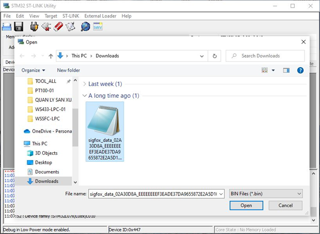

Figure 7. Loading ID&PAC
When the firmware is successfully loaded, the software will display information with image 4.
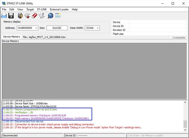
Figure 8. Successfully loading ID& PAC
Support for Flashing The Firmware in Daviteq Lorawan Sensor
1. Preparation
1.1 Prepare a ST-LINK V2 cable that connect between PC and the sensor. Details information of the cable at link:
https://www.st.com/en/development-tools/st-link-v2.html
ST-LINK V2 cable could be bought from local ST distributor at your country.
1.2 Save the updated firmware to the PC for flashing to the sensor.
1.3 Note out checksum information of the update firmware. This information will be provided by sensor manufacturer.
2. Download and install the software "STM32 ST-LINK Utility".
Computer run on Windows 7 or higher.
The software can be downloaded from the link : https://filerun.daviteq.com/wl/?id=3OVxFN7qe3R7lU9iayCSIHxH45yCM6yE
3. Plug cable from ST-LINK V2 to sensor.
With the female to female wire
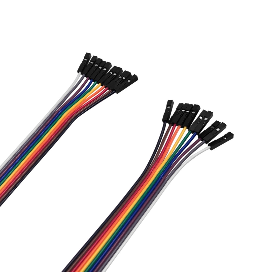
or with the provided cable by Daviteq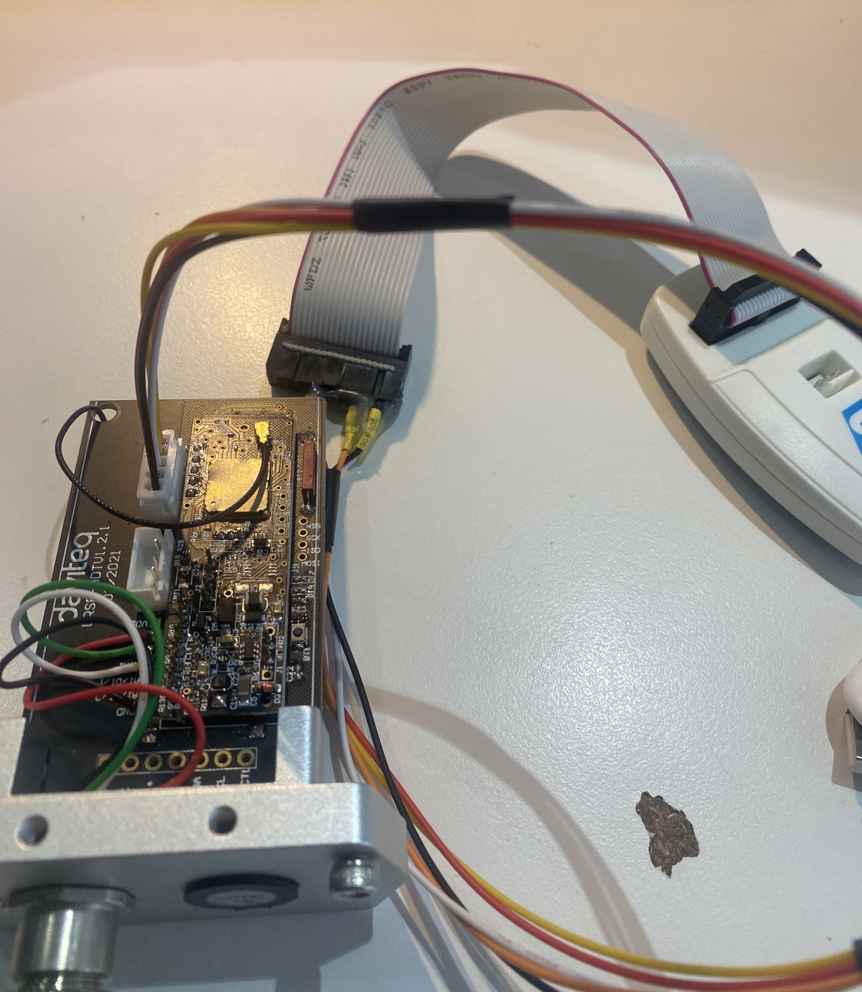
Then plug the ST-Link V2 into the computer by the USB A to Mini B cable.
4. Select the mode setting on the software.
Open STM32 ST-LINK Utility.
4.1 Target -> Settings...
4.2 Mode: select "Connect Under Reset" and check "Enable debug in Low power mode" -> OK
The order of steps 3.1 and step 3.2 indicate through the image from left to right in Table 1.
|
|
Table 1. Settings... - Mode.
5. Target the hex file for upgrading any firmware.
5.1 Target -> Program & Verify...
5.2 File path -> Browse
Basically, the firmware update specifies the sensor. In this case, please contact the instructor for more information.
Step 5.1 and step 5.2 indicate in the image from left to right in Table 2.
You must browse to select the correct file, the hex file can be used to apply for the same device type.
|
|
|
Table 2. Program & Verify... - Browse.
5.3 Open ".hex" file -> Start
In step 5.3, you need to select the hex file and load it into the device.
For example within each image of Table 3, the target is a sensor WSSFC-LPC and is used in this guide. Note the checksum then "Start"
|
|
|
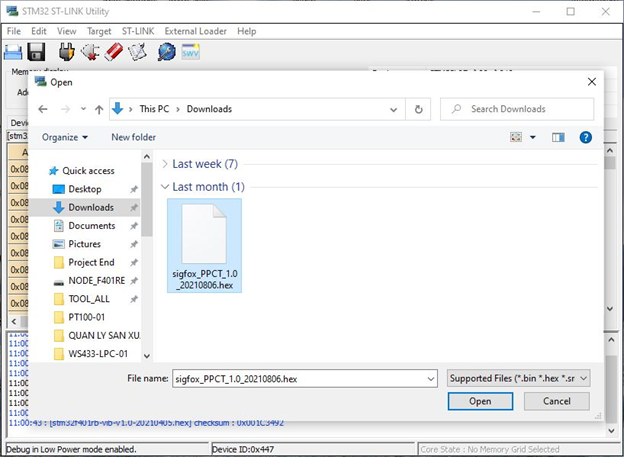
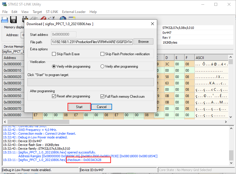
Table 3. Starting a program file to the sensor, Open - Start.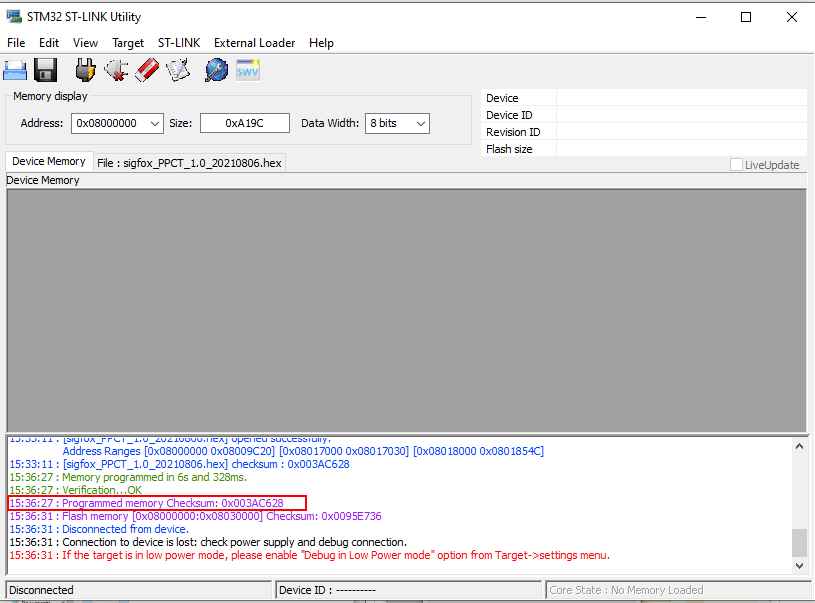
If Programmed memory Checksum equal with the .hex file checksum => Succeed
If Programmed memory Checksum not equal with the .hex file checksum => Failed