AMBIENT & PROCESS Humidity & Temperature Sensor with Modbus output MBRTU-ATH
USER GUIDE FOR AMBIENT & PROCESS HUMIDITY & TEMPERATURE SENSOR WITH MODBUS OUTPUT MBRTU-ATH
| MBRTU-ATH-MN-EN-01 |
JUN-2021 |
This document is applied for the following products
|
SKU |
MBRTU-ATH |
HW Ver. |
2.5 |
FW Ver. |
5.1 |
|
Item Code |
MBRTU-ATH-15-300 |
PROCESS HUMIDITY AND TEMPERATURE SENSOR, -40 .. +120 C, 300MM PROBE, ALL 304SS MATERIAL, SLIDING-FLANGE, RS485/MODBUSRTU, 7..48VDC SUPPLY, M12-M CONNECTOR |
|||
1. Functions Change Log
| HW Ver.
|
FW Ver. |
Release Date |
Function Change |
|
2.5 |
5.1 |
-2020 |
Innitial FW
|
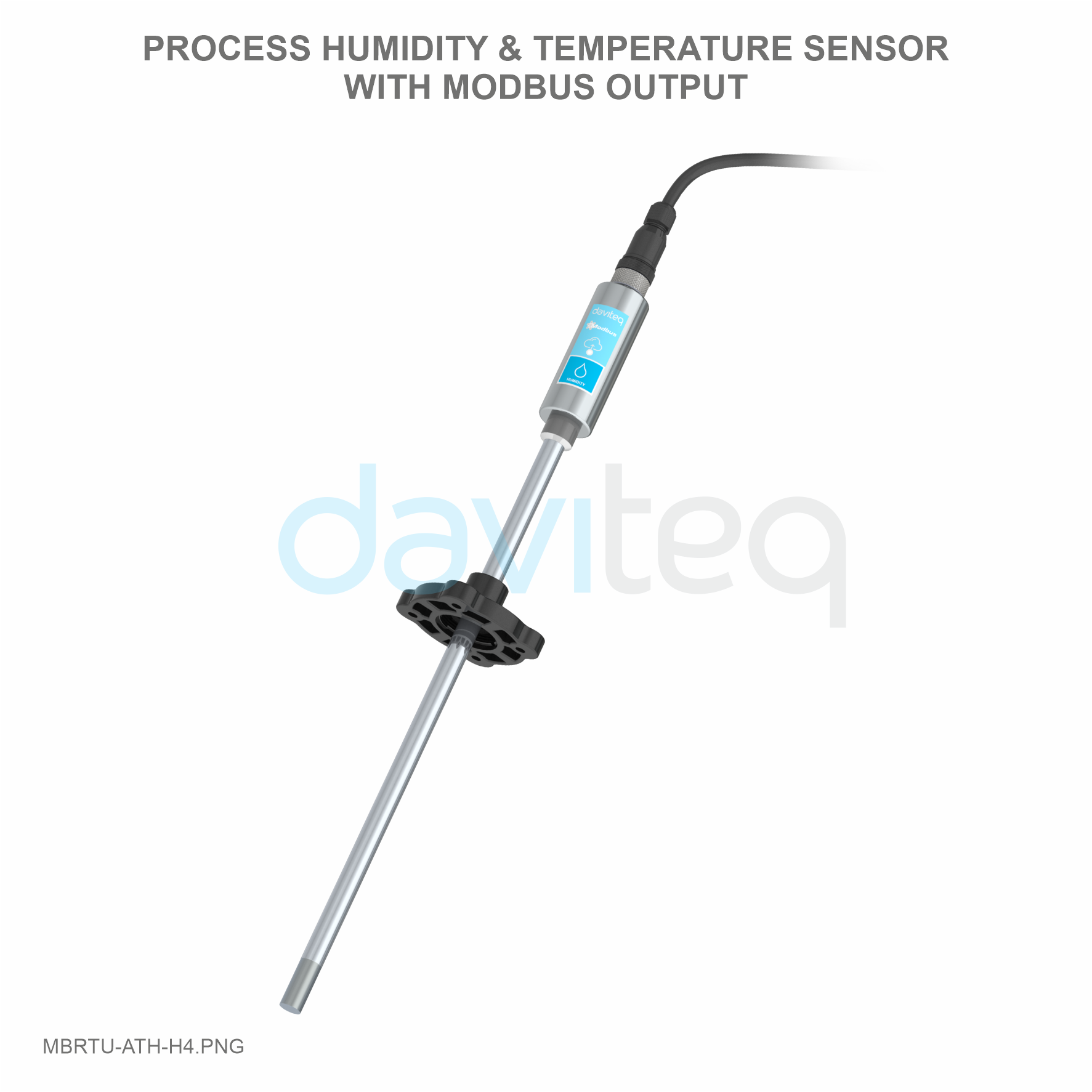
2. Introduction
MBRTU-ATH Humidity and Temperature Sensor utilizes digital temperature sensor delivers high accuracy measurement in range -40℃ to + 85℃ for ambient version or -40℃ to + 120℃ for Process version. Output is Modbus RTU for easily integrating with any PLC, controller, SCADA, BMS or IoT gateway.
- Digital sensor technology;
- High accuracy;
- Standard ModbusRTU output;
- Plug & Play.
3. Specification
| SENSOR SPECIFICATION for AMBIENT VERSION | |
| Sensor | Digital type, factory calibrated, output both Humidity & Temperature values |
| Humidity measuring range | 0 .. 100 %RH |
| Humidity accuracy | +/- 3.0% |
| Humidity resolution | 0.1% |
| Temperature measuring range | -40 .. + 85 ℃ |
| Temperature accuracy | +/- 1.0 ℃ |
| Temperature resolution | 0.1 ℃ |
| Sensor Filter | PA (for integrated version) OR 20um Alloy sintered filter (for sensor with cable) |
| SENSOR SPECIFICATION for PROCESS VERSION | |
| Sensor | Digital type, factory calibrated, output both Humidity & Temperature values |
| Humidity measuring range | 0 .. 100 %RH |
| Humidity accuracy | +/- 1.8% RH typical in 30-70%RH range and 0-80 oC |
| Humidity resolution | 0.1% |
| Temperature measuring range | -40 .. + 120 ℃ |
| Temperature accuracy | +/- 0.5 ℃ in 0-100 ℃ range |
| Temperature resolution | 0.1 ℃ |
| Sensor Filter | 20um Alloy sintered filter (for sensor with cable) |
| Sensor Probe | 12mm diameter, 304SS with sliding flange Probe length: 300mm, 600mm, 900mm |
| Working pressure | atmosphere |
| SENSOR SPECIFICATION for OUTDOOR AMBIENT VERSION -ATHP | |
| Sensor | Digital type, factory calibrated, output both Humidity & Temperature values |
| Humidity measuring range | 0 .. 100 %RH |
| Humidity accuracy | +/- 1.8% RH typical in 30-70%RH range and 0-80 oC |
| Humidity resolution | 0.1% |
| Temperature measuring range | -40 .. + 120 ℃ |
| Temperature accuracy | +/- 0.5 ℃ in 0-100 ℃ range |
| Temperature resolution | 0.1 ℃ |
| Barometric Pressure range | 300 .. 1200 mbar abs. (in -20 .. + 85 ℃) |
| Pressure accuracy | +/- 4 mbar (in full measurement range as above) |
| Pressure resolution | 0.1 mbar |
| Outdoor protection | IP67 electronics housing with Radiation shield with filter for sensor parts |
| TRANSMITTER SPECIFICATION | |
| Communication Port | RS485, ModbusRTU protocol, max 19200 baud |
| Power supply | 7..48VDC, avg. < 200mA |
| Connector | M12-male 4-pin Code A |
| Working temperature | -40 .. 85 ℃ |
| Working humidity | 0 .. 100% RH |
| Housing | 304SS |
| Rating | IP67 |
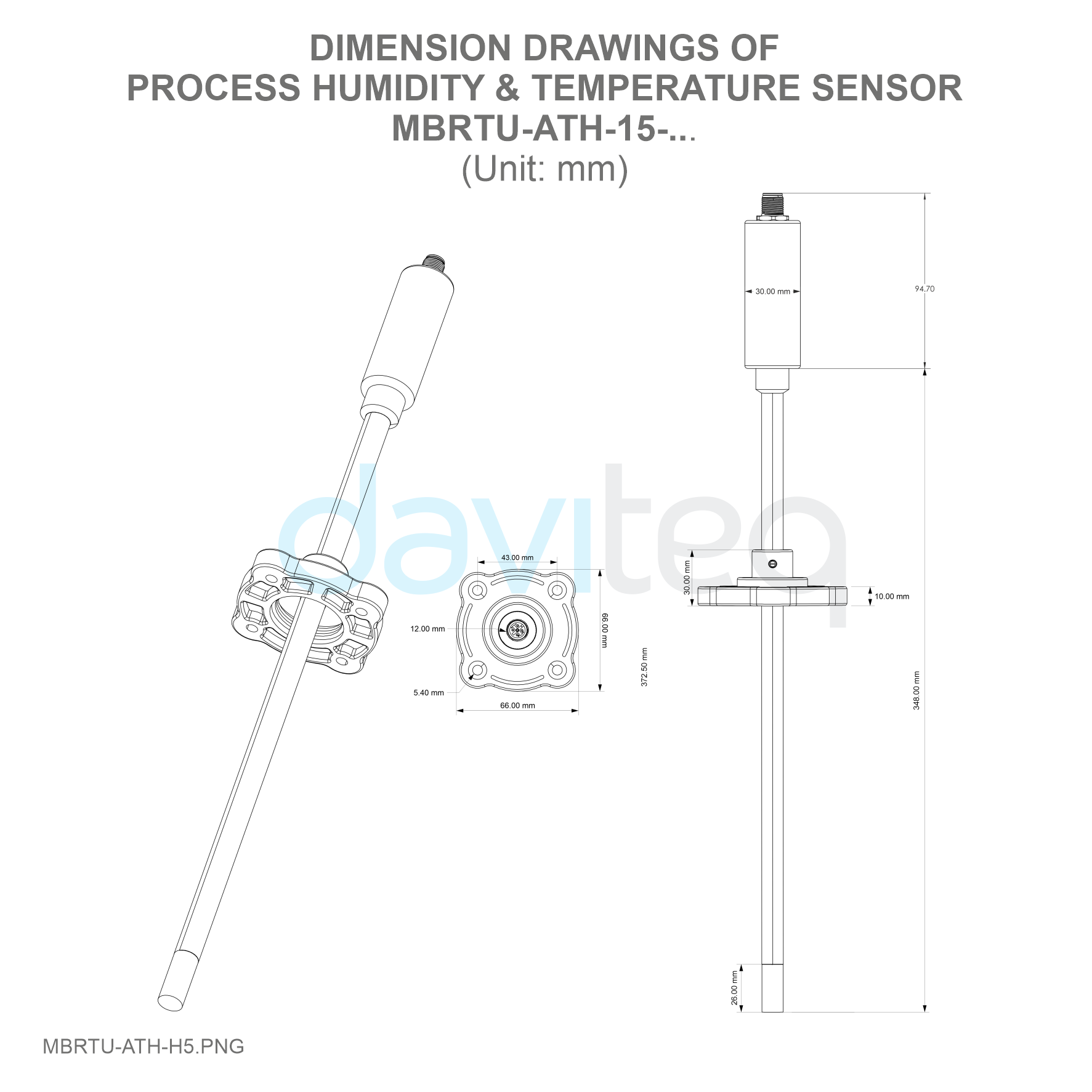
| Dimension | H100xD30 (without sensor cable) |
| Mounting | AMBIENT: SS304 L type bracket for wall mounting PROCESS: integral on probe |
| Net weight | <200 grams |
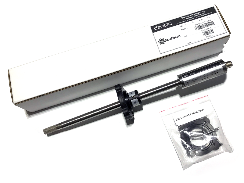
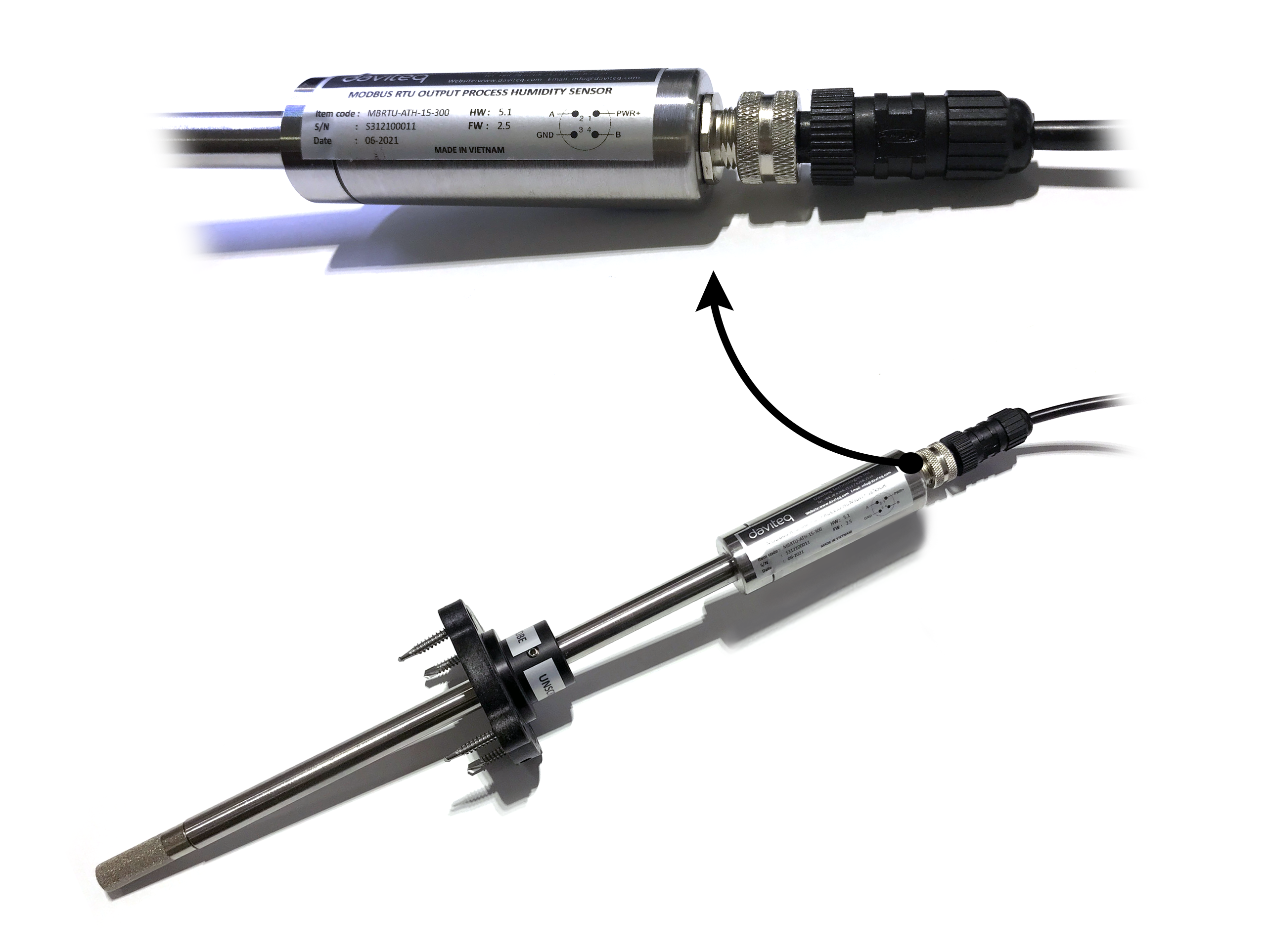
4. Product components
5. Dimensions
6. Wiring
6.1 Electrical connector
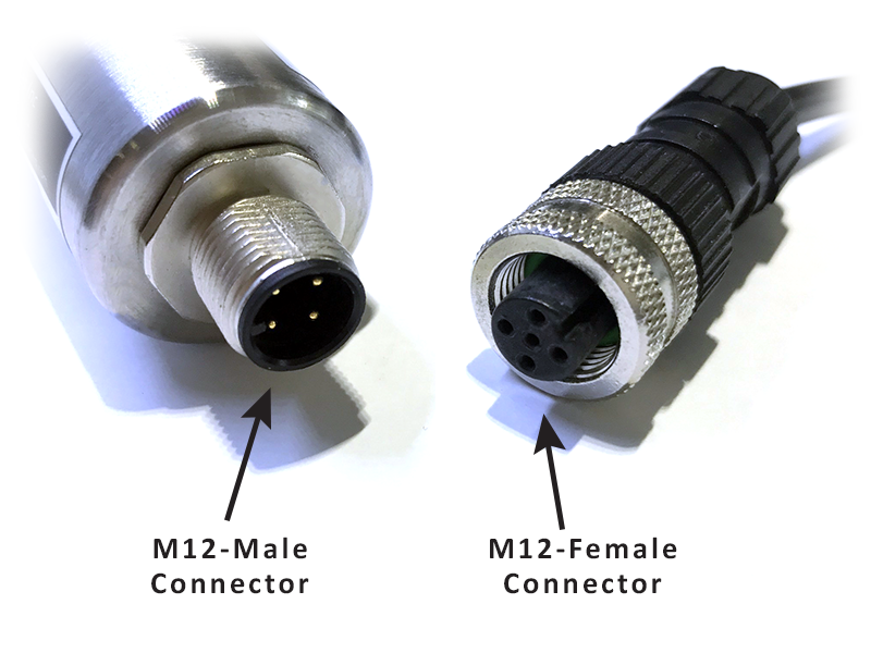
6.2 Pinout
Because the sensor uses an M12 electrical connector, please look closely at the pinouts of the M12 electrical connector as shown below.

A - B: RS485/ModbusRTU Output
PWR+: Power supply 7..48VDC
GND: Ground, 0VDC
7. Configuration
7.1 Offline Configuration
You can download Daviteq Modbus Configuration Tool with the following link:
https://filerun.daviteq.com/wl/?id=yDOjE5d6kqFlGNVVlMdFg19Aad6aw0Hs
Template File: https://filerun.daviteq.com/wl/?id=pTlOMMJNK1wF9JBszKybiupqoeWapD58
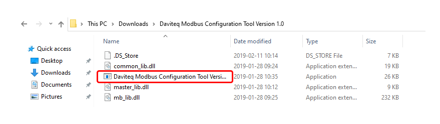
How to use the Modbus configuration software
- Unzip file and run file application "Daviteq Modbus Configuration Tool Version"
- Choose COM Port (the Port which is USB cable plugged in)
- Set the BaudRate: 9600, Parity: none
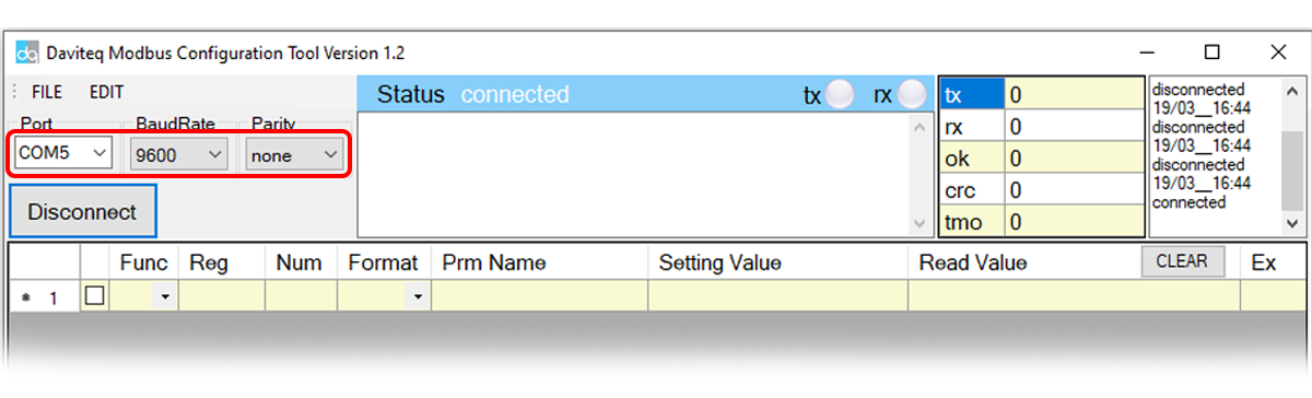
- Click “ Connect “ untill the Status displays “disconnected” to “connected“. It means the modbus sensor is being connected with computer;
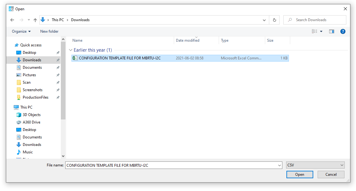
- Next, we need to import the configuration file. Go to MENU: FILE / Import New / => select the template file.
Step 3: Configure parameters of the sensor.
7.2 Memmap registers
|
Modbus |
Modbus |
Func |
Func |
# of |
Description |
Range |
Default |
Format |
Property |
Comment |
| 2 | 2 | 3 | 4 | Firmware version | string | Read |
|
|||
| 6 | 6 | 3 | 2 | Hardware version | string | Read |
|
|||
| 9 | 9 | 3 | 2 | Humidity (prm1) | 0..100% | float | Read |
Value from sensor. This value is parameter 1 of a wireless sensor node |
||
|
11 |
B |
3 |
|
1 |
|
|
|
uint16 |
Read |
Hi-Byte is error code, Lo-Byte is sensor type |
| 12 | C | 3 | 2 | Temperature (prm 2) | float | Read |
Value from sensor. This value is parameter 2 of a wireless sensor node |
|||
|
14 |
E |
3 |
|
1 |
Logic status of parameters |
|
|
uint8 |
Read |
Hi-Byte is Logic status of parameter 1, Lo-Byte is Logic status of parameter 2 |
|
15 |
F |
3 |
|
2 |
Up-Timer 1 |
|
|
uint32 |
Read |
Total time when Hi-Byte of Logic status = 1 |
|
17 |
11 |
3 |
|
2 |
Down-Timer 1 |
|
|
uint32 |
Read |
Total time when Hi-Byte of Logic status = 0 |
|
19 |
13 |
3 |
|
2 |
Rising-Edge Counter 1 |
|
|
uint32 |
Read |
Counter value when Hi-Byte of Logic status changes from 0 to 1 |
|
21 |
15 |
3 |
|
2 |
Falling-Edge Counter 1 |
|
|
uint32 |
Read |
Counter value when Hi-Byte of Logic status changes from 1 to 0 |
|
23 |
17 |
3 |
|
2 |
Up-Timer 2 |
|
|
uint32 |
Read |
Total time when Lo-Byte of Logic status = 1 |
|
25 |
19 |
3 |
|
2 |
Down-Timer 2 |
|
|
uint32 |
Read |
Total time when Lo-Byte of Logic status = 0 |
|
27 |
1B |
3 |
|
2 |
Rising-Edge Counter 2 |
|
|
uint32 |
Read |
Counter value when Lo-Byte of Logic status changes from 0 to 1 |
|
29 |
1D |
3 |
|
2 |
Falling-Edge Counter 2 |
|
|
uint32 |
Read |
Counter value when Lo-Byte of Logic status changes from 1 to 0 |
|
256 |
100 |
3 |
16 |
1 |
Modbus address |
1-247 |
1 |
uint16 |
Read/Write |
Modbus address of device |
|
257 |
101 |
3 |
16 |
1 |
Modbus baudrate |
0-1 |
0 |
uint16 |
Read/Write |
Baudrate: 0: 9600, 1: 19200 |
|
258 |
102 |
3 |
16 |
1 |
Modbus parity |
0-2 |
0 |
uint16 |
Read/Write |
Parity: 0: none, 1: odd, 2: even |
|
280 |
118 |
3 |
16 |
2 |
a1
|
|
1 |
float |
Read/Write |
Scale value of parameter_1 = (a1 * Raw sensor value of parameter_1) + b1. For sensor value scale |
|
282 |
11A |
3 |
16 |
2 |
b1 |
|
0 |
float |
Read/Write |
Scale value of parameter_1 = (a1 * Raw sensor value of parameter_1) + b1. For sensor value scale |
|
284 |
11C |
3 |
16 |
2 |
a2 |
|
1 |
float |
Read/Write |
Scale value of parameter_2 = (a2 * Raw sensor value of parameter_2) + b2. For sensor value scale |
|
286 |
11E |
3 |
16 |
2 |
b2 |
|
0 |
float |
Read/Write |
Scale value of parameter_2 = (a2 * Raw sensor value of parameter_2) + b2. For sensor value scale |
|
290 |
122 |
3 |
16 |
2 |
High_threshold_1
|
|
|
float |
Read/Write |
High threshold value for parameter 1 |
|
292 |
124 |
3 |
16 |
2 |
Low_threshold_1 |
|
|
float |
Read/Write |
Low threshold value for parameter 1 |
|
294 |
126 |
3 |
16 |
2 |
High_threshold_2 |
|
|
float |
Read/Write |
High threshold value for parameter 2 |
|
296 |
128 |
3 |
16 |
2 |
Low_threshold_2 |
|
|
float |
Read/Write |
Low threshold value for parameter 2 |
8. Installation
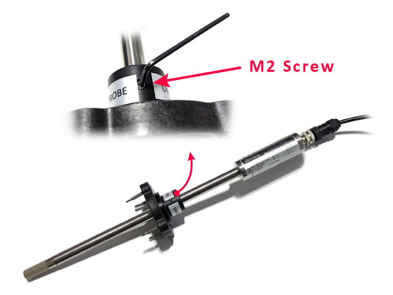
8.1 Height adjustment
The flange can be moved throughout the sensor body and can be fixed with the M2 countersunk hex nut.
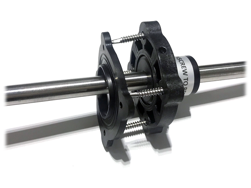
8.2 Accessory installation
The accessories are installed as shown
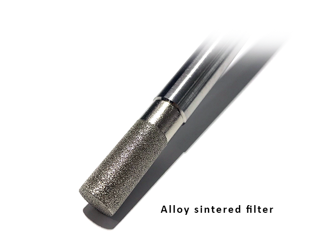
8.3 Filter
Please avoid contaminating the sensor filter when installing to get the most accurate measurement
9. Applications

10. Support contacts
|
Manufacturer Daviteq Technologies Inc
No.11 Street 2G, Nam Hung Vuong Res., An Lac Ward, Binh Tan Dist., Ho Chi Minh City, Vietnam. Email: info@daviteq.com | www.daviteq.com |