User Guide for Modbus Configuration Tool
| AUG-2020 |
Daviteq Modbus Configuration Tool
| HW Ver. | Release Date |
| 1.0 | NOV-2019 |
| 1.4 |
OCT-2020 |
| 2.03 |
DEC-2021 |
1. Install Tool
1.1 Download Tool
Install the Modbus Configuration Software in the link below
https://filerun.daviteq.com/wl/?id=yDOjE5d6kqFlGNVVlMdFg19Aad6aw0Hs
2.2 Running Tool
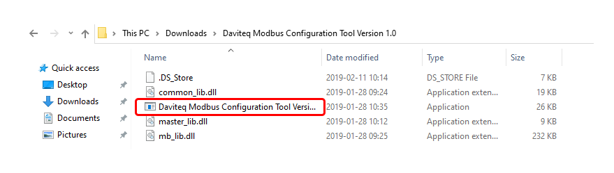
After unzip file, open the folder and run the application (Daviteq Modbus Configuration Tool Version).
2. Configuration
2.1 Connection
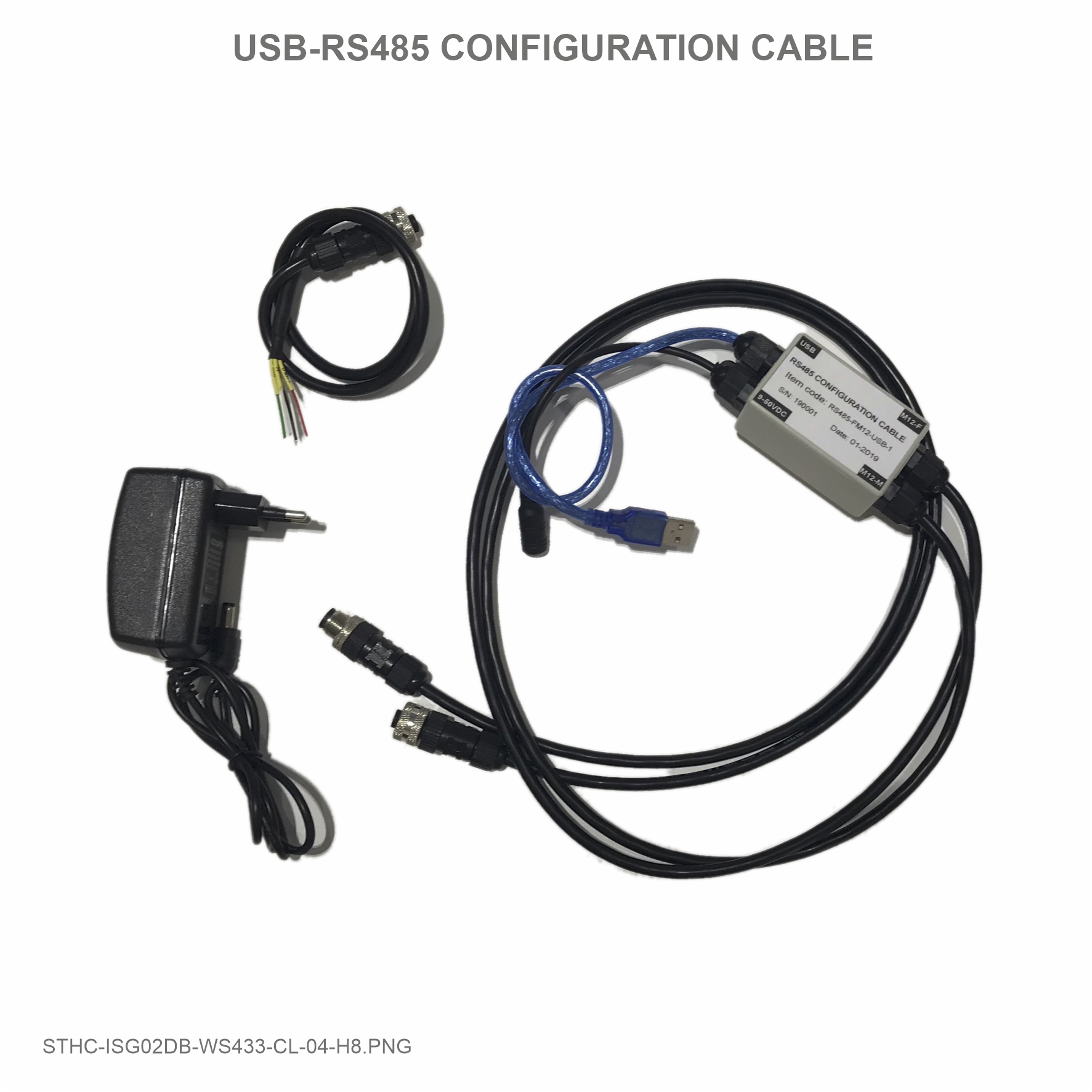
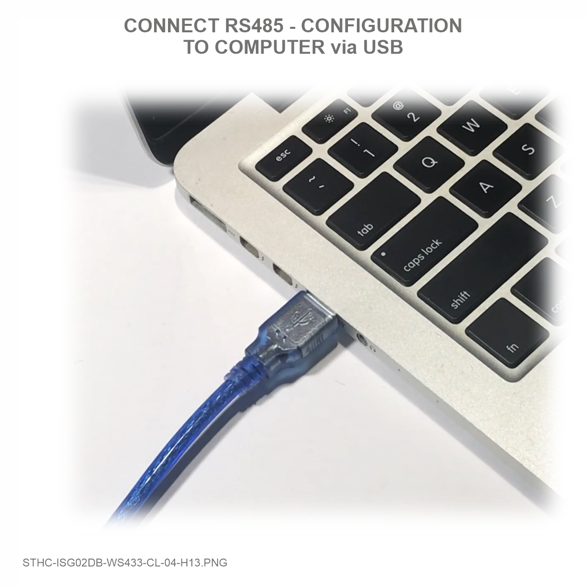
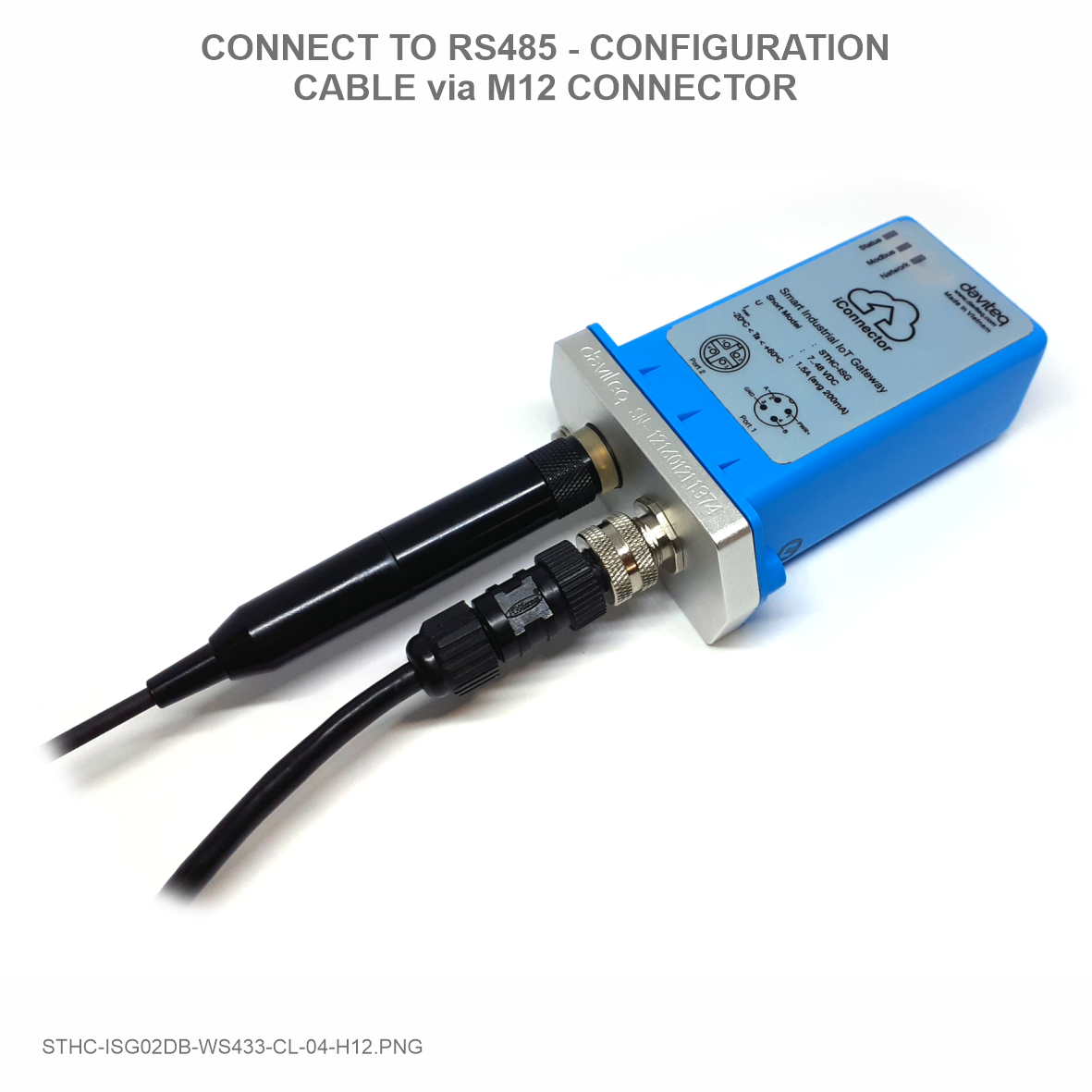
Step 1: Connect the configuration cable to the PC and Modbus device.
 |
 |
 |
 |
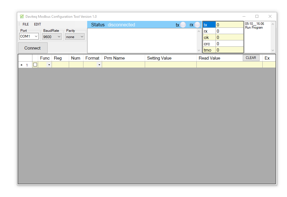
Step 2: Choose COM Port (the Port which is USB cable plugged in). Set the BaudRate: 9600, Parity: none
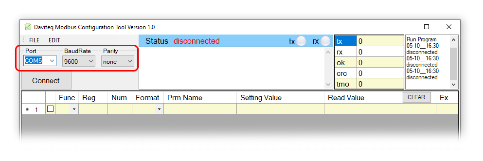
If you don't see any COM port in the list, please download the following driver and install
Modbus Configuration Cable COM port driver for PC
How to install driver
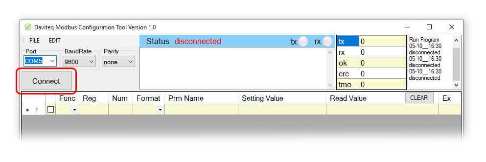
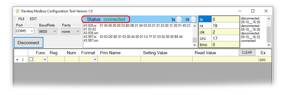
Step 3: Click “ Connect “ untill the Status displays “disconnected” to “connected“. It means the Modbus device is being connected with computer;
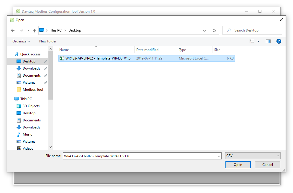
Step 4: Import the configuration file for Modbus Device by importing the csv file: Go to MENU: FILE / Import New /
Then select the template file.
Example: We import template file of Wireless Co-ordinator WR433-AP-EN-02 - Template_WR433_V1.6.csv
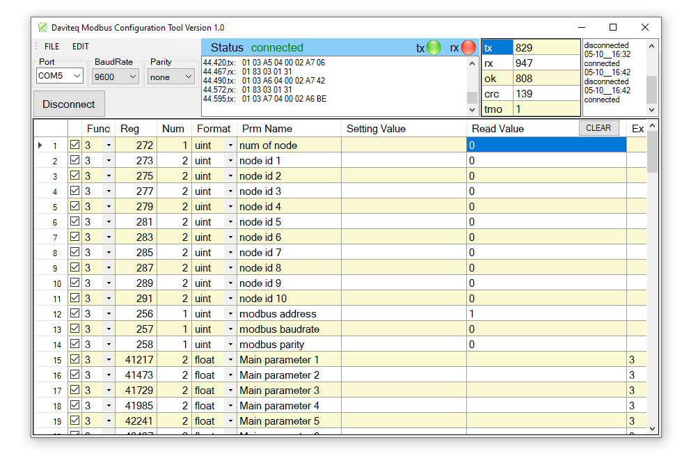
There are 3 Function:
- Function 3: Read holding registers
- Function 4: Read input registers
- Function 16: Preset Multiple registers
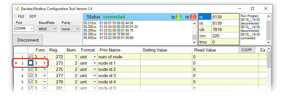
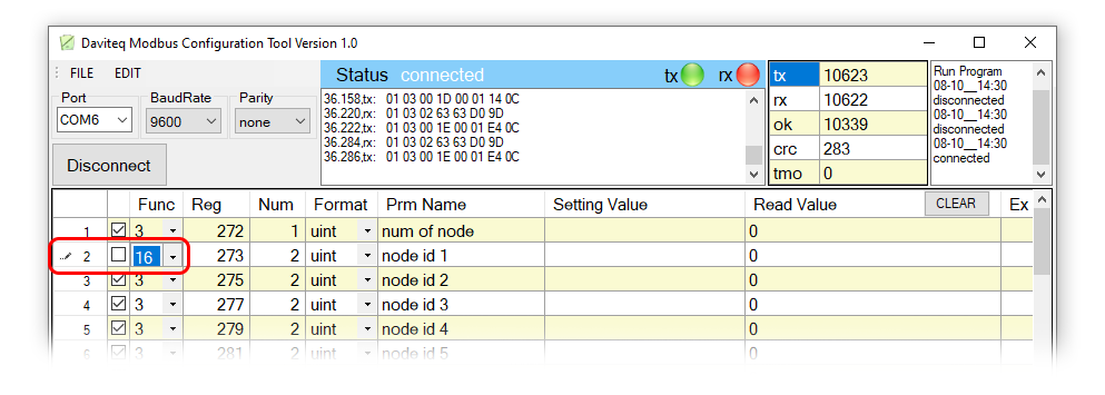
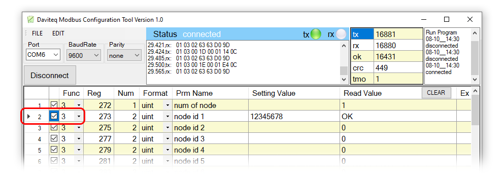
2.1 Write Value into Modbus Device with Function 16
Example: We change the value Node id 1 from 0 to 12345678 using Func 16.
Step 1: Uncheck Func 3, then Click on the arrow and change Func from 3 to 16;
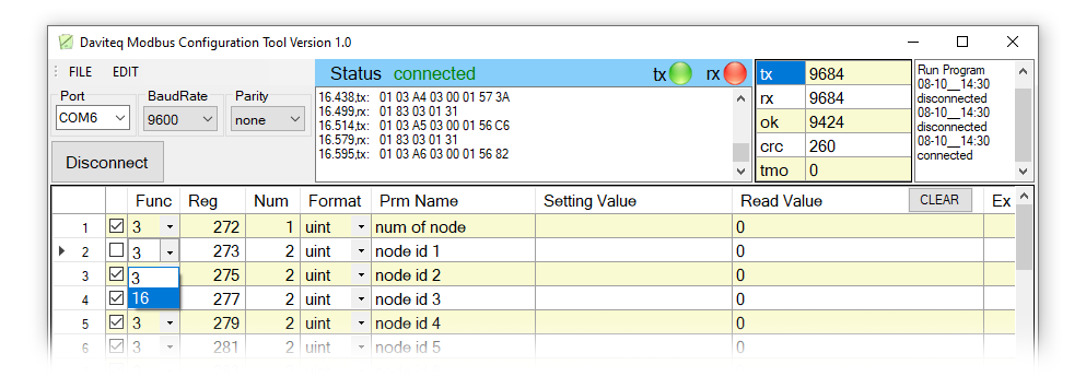
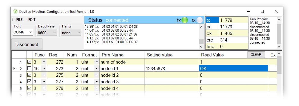
Step 2: Type in Setting Value the Node id 1, then check the Func 16 box.
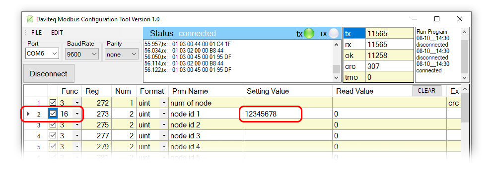
if Read Value show OK which mean it's wrote successful.
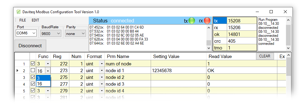
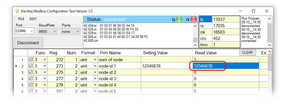
2.1 Read Value from Modbus Device with Function 3
After writing the value, we will check the value entered with Func 3. Func 3 is used to read holding registers.
Step 1: Click on the arrow and change Func from 16 to 3.
Step 2: Check the box of Func 3. If it shows that the value in Read Value is the same as the value entered, it means that the data entered was successful.
3. Troubleshooting
| No. | Phenomena | Reason | Solutions |
| 1 | Cannot connect to software |
|
|
| 2 | COM port does not appear in the select list |
|
|
| 3 | Cannot see any register on software | The template file has not been imported | Go to File/Import New to import the template file |
| 4 | See registers that do not match the memmap table of the device rs485 or sensor is configuring | The template file imported incorrectly | Go to the correct manual page of the product configuring and download the template file, then import the template file into the software |
4. Support contacts
|
Manufacturer
Daviteq Technologies Inc Email: info@daviteq.com | www.daviteq.com
|
Distributor in Australia and New Zealand
Templogger Pty Ltd Tel: 1800 LOGGER Email: contact@templogger.net |

No Comments