USER GUIDE FOR PRESSURE SENSOR RS485-MODBUS RTU OUTPUT
|
JUN-2020 |
This document is applied for the following products
1. Pressure Sensor RS485-Modbus RTU Output

2. Specification
| Sensing Technology | Advanced PIEZO/Capacitance technology |
| Measuring range | Select from -1 .. + 35 bar Gage/Absolute/Sealed Gage |
| Over pressure protection | 1.5 x Span |
| Accuracy | 0.5% of span |
| Stability | < 0.3% span/year |
| Wetted parts | 304SS/316SS |
| Measuring Fluids | Any fluid which is workable with materials 304SS/316SS |
| Working temperature | -10 .. + 80 oC |
| Process connection | Standard G1/4 or Others (consult factory) |
| RS485 output | Default address: 1, baudrate: 9600, parity: none, data: 8 bit, stop bit: 1 |
| Power supply | 9..36VDC |
| Consumption | 5mA @ 12VDC supply |
3. Product Pictures

4. Wiring
Please wiring as shown below:


Memmap resgisters:
|
Modbus |
Modbus |
Function |
Function |
# of |
Range |
Default |
Format |
Property |
Comment |
|
0 |
0 |
3 |
|
2 |
|
|
string |
Read |
|
|
2 |
2 |
3 |
|
4 |
|
|
string |
Read |
|
|
6 |
6 |
3 |
|
2 |
|
|
string |
Read |
|
|
8 |
8 |
3 |
|
1 |
10, 30, 60, 99 |
|
uint16 |
Read |
Battery level, only 04 levels: 10%, 30%, 60% and 99% (full). When 10% ==> should replace the battery |
|
9 |
9 |
3 |
|
2 |
0..100% |
|
float |
Read |
Value from pressure process sensor. This value is parameter 1 of a wireless sensor node |
|
11 |
B |
3 |
|
1 |
|
|
uint16 |
Read |
Hi-Byte is error code, Lo-Byte is sensor type |
|
12 |
C |
3 |
|
2 |
|
|
float |
Read |
Value from pressure process sensor. This value is parameter 2 of a wireless sensor node |
|
14 |
E |
3 |
|
1 |
|
|
uint8 |
Read |
Hi-Byte is Logic status of parameter 1, Lo-Byte is Logic status of parameter 2 |
|
15 |
F |
3 |
|
2 |
|
|
uint32 |
Read |
Total time when Hi-Byte of Logic status = 1 |
|
17 |
11 |
3 |
|
2 |
|
|
uint32 |
Read |
Total time when Hi-Byte of Logic status = 0 |
|
19 |
13 |
3 |
|
2 |
|
|
uint32 |
Read |
Counter value when Hi-Byte of Logic status changes from 0 to 1 |
|
21 |
15 |
3 |
|
2 |
|
|
uint32 |
Read |
Counter value when Hi-Byte of Logic status changes from 1 to 0 |
|
23 |
17 |
3 |
|
2 |
|
|
uint32 |
Read |
Total time when Lo-Byte of Logic status = 1 |
|
25 |
19 |
3 |
|
2 |
|
|
uint32 |
Read |
Total time when Lo-Byte of Logic status = 0 |
|
27 |
1B |
3 |
|
2 |
|
|
uint32 |
Read |
Counter value when Lo-Byte of Logic status changes from 0 to 1 |
|
29 |
1D |
3 |
|
2 |
|
|
uint32 |
Read |
Counter value when Lo-Byte of Logic status changes from 1 to 0 |
|
256 |
100 |
3 |
16 |
1 |
1-247 |
1 |
uint16 |
Read/Write |
Modbus address of device |
|
257 |
101 |
3 |
16 |
1 |
0-1 |
0 |
uint16 |
Read/Write |
Baudrate: 0: 9600, 1: 19200 |
|
258 |
102 |
3 |
16 |
1 |
0-2 |
0 |
uint16 |
Read/Write |
Parity: 0: none, 1: odd, 2: even |
|
259 |
103 |
3 |
16 |
21 |
|
|
|
|
|
|
280 |
118 |
3 |
16 |
2 |
|
1 |
float |
Read/Write |
Scale value of parameter_1 = (a1 * Raw sensor value of parameter_1) + b1. For sensor value scale |
|
282 |
11A |
3 |
16 |
2 |
|
0 |
float |
Read/Write |
Scale value of parameter_1 = (a1 * Raw sensor value of parameter_1) + b1. For sensor value scale |
|
284 |
11C |
3 |
16 |
2 |
|
1 |
float |
Read/Write |
Scale value of parameter_2 = (a2 * Raw sensor value of parameter_2) + b2. For sensor value scale |
|
286 |
11E |
3 |
16 |
2 |
|
0 |
float |
Read/Write |
Scale value of parameter_2 = (a2 * Raw sensor value of parameter_2) + b2. For sensor value scale |
|
288 |
120 |
3 |
16 |
2 |
|
|
float |
Read/Write |
|
|
290 |
122 |
3 |
16 |
2 |
|
|
float |
Read/Write |
High threshold value for parameter 1 |
|
292 |
124 |
3 |
16 |
2 |
|
|
float |
Read/Write |
Low threshold value for parameter 1 |
|
294 |
126 |
3 |
16 |
2 |
|
|
float |
Read/Write |
High threshold value for parameter 2 |
|
296 |
128 |
3 |
16 |
2 |
|
|
float |
Read/Write |
Low threshold value for parameter 2 |
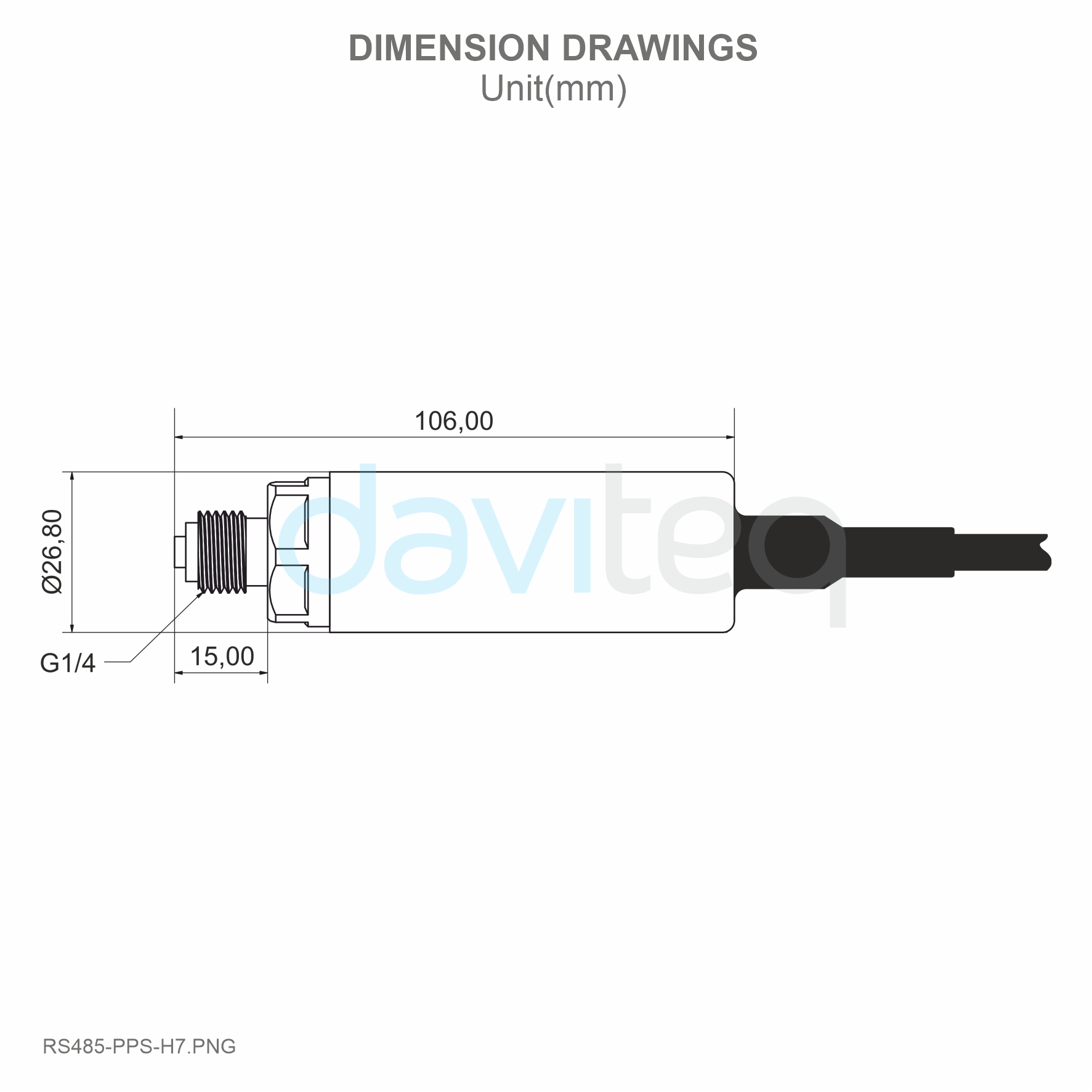
5. Dimensions
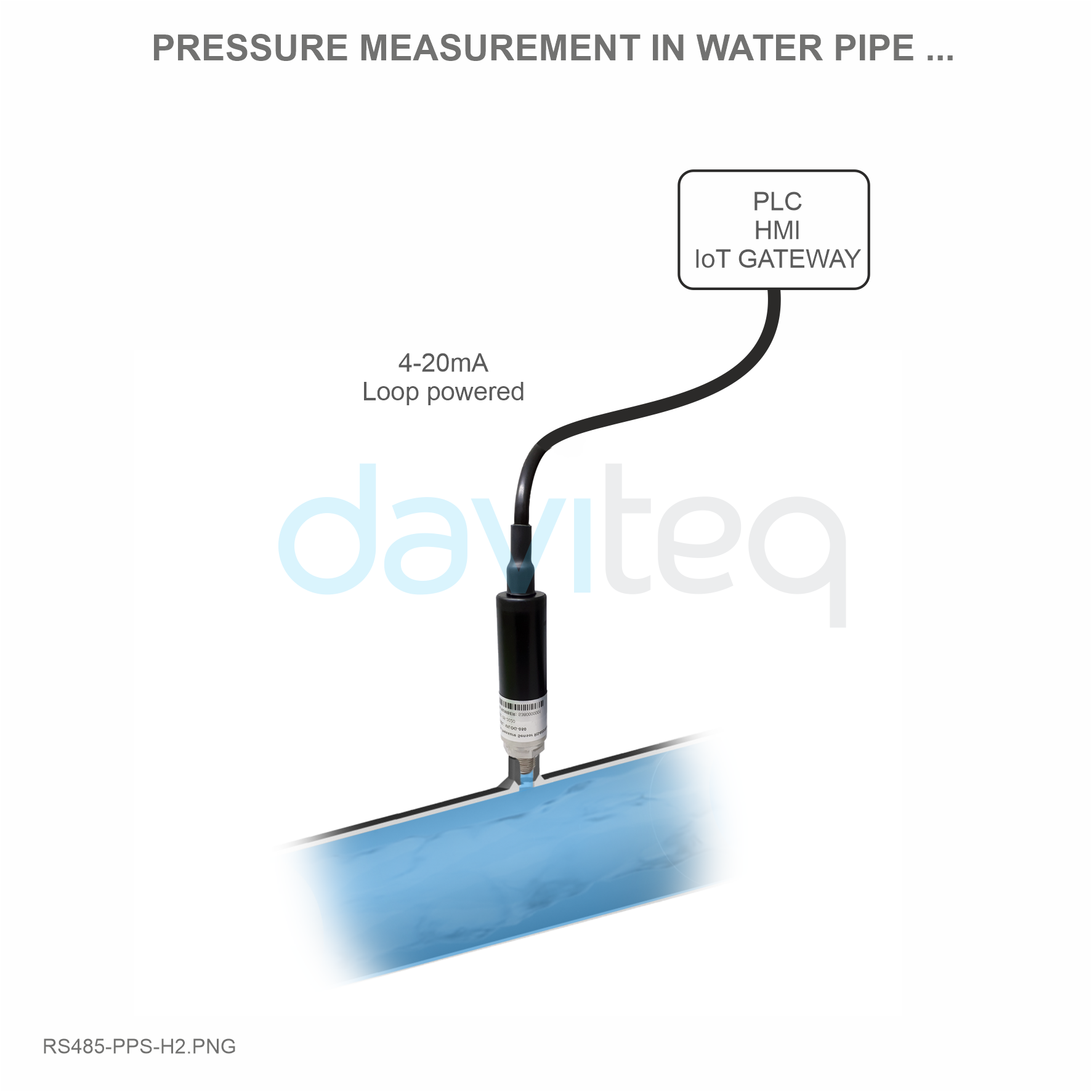
6. Applications
|
 |
 |
 |
7. Support contacts
|
Manufacturer Daviteq Technologies Inc
No.11 Street 2G, Nam Hung Vuong Res., An Lac Ward, Binh Tan Dist., Ho Chi Minh City, Vietnam. Email: info@daviteq.com | www.daviteq.com |
No Comments