USER GUIDE FOR MODBUS REMOTE IO MODULE STHM-MBIO
| STHM-MBIO-MN-EN-01 |
JUN-2020 |
This document is applied for the following products
| SKU | STHM-MBIO | HW Ver. | 1.0 | FW Ver. | 1.0 |
| Item Code |
STHM-MBIO-4AI4DI4RL-NR | RS485/ModbusRTU Remote I/O Module, 4AI/DI, 4DI, 4xRelay, 1xPulse Output, Non-ROHS | |||
1. Functions Change Log
| HW Ver. | FW Ver. | Release Date | Functions Change |
| 1.0 | 1.0 | JUN-2020 |
|
|
|
2. Introduction
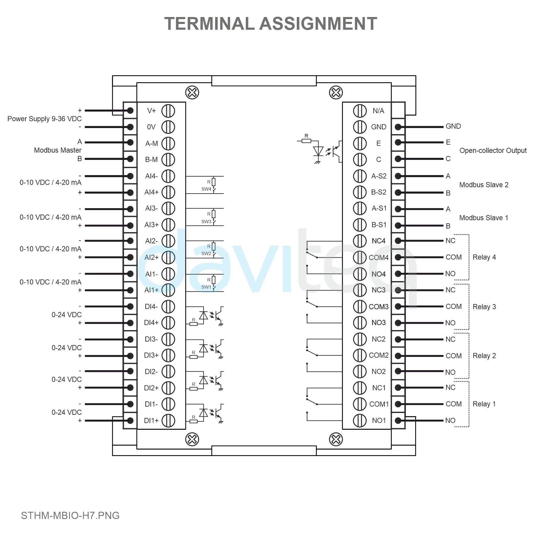
STHM-MBIO is Modbus RTU Remote IO Module to help PLC/SCADA/BMS and any IoTs gateway extend the number of I/O capabilities. STHM-MBIO has a simple but powerful design with 4 AI/DI, 4 DI, 4 Relay, 1 Pulse PWM output, 1 RS485 Master ModbusRTU and 2 RS485 Slave ModbusRTU allow them to connect to more devices such as sensors, meters, … directly and easily. The module with advanced technology provide high stability and reliability, multiple functions and easy installation with DIN rail design. The module can be used in many applications such as machine monitoring, manufacture monitoring, environmental monitoring, smart farms, etc.

3. Specification
| Digital Inputs | 04 x Ports, opto-coupler, 4.7 kohms input resisrtance, 5000V rms isolation, Logic 0 (0-1VDC), Logic 1 (5-24VDC), Functions: logic status 0/1 or Pulse counting (32 bit counter with max 2kHz pulse) |
| Analog Inputs | 04 x Ports, select between 0-10VDC input or 0-20mA input, 12 bit Resolution, can be configured as Digital input by DIP switch (max 10VDC input) |
| Relay Output | 04 x Ports, electro-mechanical Relays, SPDT, contact rating 24VDC/2A or 250VAC/5A, LED indicators, Latch control enable |
| Pulse Output | 01 x Ports, open-collector, opto-isolation, max 10mA and 80VDC, On/off control, Pulser (max 2.5Khz, max 65535 Pulses) or PWM (max 2.5Khz) |
| Communication | 02 x ModbusRTU-Slave, 01 x ModbusRTU-Master, RS485, speed 9600 or 19200, LED indicator |
| Reset button | For resetting 02 x RS485 Slave port to default setting (9600, None parity, 8 bit) |
| Power supply | 9..36VDC |
| Consumption | 80mA @ 24VDC supply |
| Mounting type | DIN rail |
| Terminal Block | pitch 5.0mm, rating 300VAC, wire size 12-24AWG |
| Working temperature/humidity | 0..60 degC / 95%RH non-condensing |
| Dimension | H87xW117xD42 |
| Net weight | 80 grams |
4. Applications
|
 |
 |
 |
 |
 |
5. Operation Principle
5.1 Modbus communication
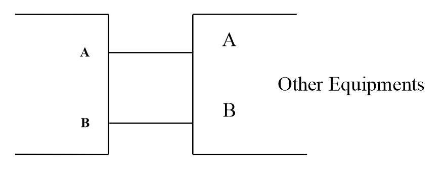
02 x RS485/ModbusRTU-Slave
Protocol: Modbus RTU
Address: 1 - 247, 0 is the Broadcast address
Baud rate: 9600 , 19200
Parity: none, odd, even
Default configuration: Address: 1, Baudrate slave 1: 9600, Parity slave 1: none, Baudrate slave 2: 9600, Parity slave 2: none
Status indicator LED:
- Led on: modbus communication OK
- Led blinking: received data but modbus communication incorrect, due to wrong Modbus configuration: address, baudrate
- Led off: STHM-MBIO received no data, check the connection
Memmap resgisters
READ uses function 03, WRITE uses function 16
| Modbus Register |
Hex Addr | # of Registers | Description | Range | Default | Format | Properties | Comments |
| Data zone | ||||||||
| 0 | 0 | 2 | device info | IOMD | string | Read | ||
| 2 | 2 | 4 | firmware version | 1.0 | string | Read | ||
| 6 | 6 | 2 | hardware version | 1.1 | string | Read | ||
| 8 | 8 | 1 | DI1___DI2: digital status | 0-1 | uint8 | Read | H_byte: DI1 L_byte: DI2 |
|
| 9 | 9 | 1 | DI3___DI4: digital status | 0-1 | uint8 | Read | H_byte: DI3 L_byte: DI4 |
|
| 10 | A | 1 | AI1___AI2: digital status | 0-1 | uint8 | Read | H_byte: AI1 L_byte: AI2 |
|
| 11 | B | 1 | AI3___AI4: digital status | 0-1 | uint8 | Read | H_byte: AI3 L_byte: AI4 |
|
| 12 | C | 1 | AI1: analog value | uint16 | Read | |||
| 13 | D | 1 | AI2: analog value | uint16 | Read | |||
| 14 | E | 1 | AI3: analog value | uint16 | Read | |||
| 15 | F | 1 | AI4: analog value | uint16 | Read | |||
| 16 | 10 | 2 | AI1: scaled value | float | Read | |||
| 18 | 12 | 2 | AI2: scaled value | float | Read | |||
| 20 | 14 | 2 | AI3: scaled value | float | Read | |||
| 22 | 16 | 2 | AI4: scaled value | float | Read | |||
| 24 | 18 | 1 | relay 1 | 0-1 | uint16 | Read/Write | ||
| 25 | 19 | 1 | relay 2 | 0-1 | uint16 | Read/Write | ||
| 26 | 1A | 1 | relay 3 | 0-1 | uint16 | Read/Write | ||
| 27 | 1B | 1 | relay 4 | 0-1 | uint16 | Read/Write | ||
| 28 | 1C | 1 | open collector ctrl | 0-3 | uint16 | Read/Write | 0: off 1: on 2: pwm, generate pulse continuously 3: generate pulse , when there are enough pulses ctrl = 0 |
|
| 29 | 1D | 1 | spare | |||||
| 30 | 1E | 2 | counter DI1 | uint32 | Read/Write | counter can write, erase | ||
| 32 | 20 | 2 | counter DI2 | uint32 | Read/Write | counter can write, erase | ||
| 34 | 22 | 2 | counter DI3 | uint32 | Read/Write | counter can write, erase | ||
| 36 | 24 | 2 | counter DI4 | uint32 | Read/Write | counter can write, erase | ||
| 38 | 26 | 2 | counter AI1 | uint32 | Read/Write | counter writable, erasable, max frequency 10Hz | ||
| 40 | 28 | 2 | counter AI2 | uint32 | Read/Write | counter writable, erasable, max frequency 10Hz | ||
| 42 | 2A | 2 | counter AI3 | uint32 | Read/Write | counter writable, erasable, max frequency 10Hz | ||
| 44 | 2C | 2 | counter AI4 | uint32 | Read/Write | counter writable, erasable, max frequency 10Hz | ||
| 46 | 2E | 2 | DI1: time on | uint32 | Read/Write | sec | ||
| 48 | 30 | 2 | DI2: time on | uint32 | Read/Write | sec | ||
| 50 | 32 | 2 | DI3: time on | uint32 | Read/Write | sec | ||
| 52 | 34 | 2 | DI4: time on | uint32 | Read/Write | sec | ||
| 54 | 36 | 2 | AI1: time on | uint32 | Read/Write | sec | ||
| 56 | 38 | 2 | AI2: time on | uint32 | Read/Write | sec | ||
| 58 | 3A | 2 | AI3: time on | uint32 | Read/Write | sec | ||
| 60 | 3C | 2 | AI4: time on | uint32 | Read/Write | sec | ||
| 62 | 3E | 2 | DI1: time off | uint32 | Read/Write | sec | ||
| 64 | 40 | 2 | DI2: time off | uint32 | Read/Write | sec | ||
| 66 | 42 | 2 | DI3: time off | uint32 | Read/Write | sec | ||
| 68 | 44 | 2 | DI4: time off | uint32 | Read/Write | sec | ||
| 70 | 46 | 2 | AI1: time off | uint32 | Read/Write | sec | ||
| 72 | 48 | 2 | AI2: time off | uint32 | Read/Write | sec | ||
| 74 | 4A | 2 | AI3: time off | uint32 | Read/Write | sec | ||
| 76 | 4C | 2 | AI4: time off | uint32 | Read/Write | sec | ||
| 78 | 4E | 50 | spare | |||||
| 128 | 80 | 2 | none reset counter DI1 | uint32 | Read | counter cannot be written or erased | ||
| 130 | 82 | 2 | none reset counter DI2 | uint32 | Read | counter cannot be written or erased | ||
| 132 | 84 | 2 | none reset counter DI3 | uint32 | Read | counter cannot be written or erased | ||
| 134 | 86 | 2 | none reset counter DI4 | uint32 | Read | counter cannot be written or erased | ||
| 136 | 88 | 2 | none reset counter AI1 | uint32 | Read | counter cannot be written or erased, max frequency 10Hz | ||
| 138 | 8A | 2 | none reset counter AI2 | uint32 | Read | counter cannot be written or erased, max frequency 10Hz | ||
| 140 | 8C | 2 | none reset counter AI3 | uint32 | Read | counter cannot be written or erased, max frequency 10Hz | ||
| 142 | 8E | 2 | none reset counter AI4 | uint32 | Read | counter cannot be written or erased, max frequency 10Hz | ||
| 144 | 90 | 1 | AI1: scaled value | uint16 | Read | |||
| 145 | 91 | 1 | AI2: scaled value | uint16 | Read | |||
| 146 | 92 | 1 | AI3: scaled value | uint16 | Read | |||
| 147 | 93 | 1 | AI4: scaled value | uint16 | Read | |||
| Configuration Zone | ||||||||
| 256 | 100 | 1 | modbus address slave | 1-247 | 1 | uint16 | Read/Write | |
| 257 | 101 | 1 | modbus baudrate slave 1 | 0-1 | 0 | uint16 | Read/Write | 0: 9600, 1: 19200 |
| 258 | 102 | 1 | modbus parity slave 1 | 0-2 | 0 | uint16 | Read/Write | 0: none, 1: odd, 2: even |
| 259 | 103 | 9 | serial number | string | Read/Write(PW) | |||
| 268 | 10C | 2 | password for setting | uint32 | Read/Write | |||
| 270 | 10E | 1 | counter DI1: filter time | 500 | uint16 | Read/Write | x0.1ms | |
| 271 | 10F | 1 | counter DI2: filter time | 500 | uint16 | Read/Write | x0.1ms | |
| 272 | 110 | 1 | counter DI3: filter time | 500 | uint16 | Read/Write | x0.1ms | |
| 273 | 111 | 1 | counter DI4: filter time | 500 | uint16 | Read/Write | x0.1ms | |
| 274 | 112 | 2 | counter DI1: max number | 1000000 | uint32 | Read/Write | ||
| 276 | 114 | 2 | counter DI2: max number | 1000000 | uint32 | Read/Write | ||
| 278 | 116 | 2 | counter DI3: max number | 1000000 | uint32 | Read/Write | ||
| 280 | 118 | 2 | counter DI4: max number | 1000000 | uint32 | Read/Write | ||
| 282 | 11A | 1 | counter DI: power on reset | 0 | uint16 | Read/Write | bit 0: DI1 (0: not reset, 1: reset) bit 1: DI2 bit 2: DI3 bit 3: DI4 |
|
| 283 | 11B | 1 | counter AI1: threshold logic 0 | 500 | uint16 | Read/Write | ||
| 284 | 11C | 1 | counter AI1: threshold logic 1 | 1800 | uint16 | Read/Write | ||
| 285 | 11D | 1 | counter AI2: threshold logic 0 | 500 | uint16 | Read/Write | ||
| 286 | 11E | 1 | counter AI2: threshold logic 1 | 1800 | uint16 | Read/Write | ||
| 287 | 11F | 1 | counter AI3: threshold logic 0 | 500 | uint16 | Read/Write | ||
| 288 | 120 | 1 | counter AI3: threshold logic 1 | 1800 | uint16 | Read/Write | ||
| 289 | 121 | 1 | counter AI4: threshold logic 0 | 500 | uint16 | Read/Write | ||
| 290 | 122 | 1 | counter AI4: threshold logic 1 | 1800 | uint16 | Read/Write | ||
| 291 | 123 | 2 | counter AI1: max number | 1000000 | uint32 | Read/Write | ||
| 293 | 125 | 2 | counter AI2: max number | 1000000 | uint32 | Read/Write | ||
| 295 | 127 | 2 | counter AI3: max number | 1000000 | uint32 | Read/Write | ||
| 297 | 129 | 2 | counter AI4: max number | 1000000 | uint32 | Read/Write | ||
| 299 | 12B | 1 | counter AI: power on reset | 0 | uint16 | Read/Write | bit 0: AI1 (0: not reset, 1: reset) bit 1: AI2 bit 2: AI3 bit 3: AI4 |
|
| 300 | 12C | 1 | AI1: scale in 1 | uint16 | Read/Write | |||
| 301 | 12D | 1 | AI1: scale in 2 | uint16 | Read/Write | |||
| 302 | 12E | 2 | AI1: scale out 1 | float | Read/Write | |||
| 304 | 130 | 2 | AI1: scale out 2 | float | Read/Write | |||
| 306 | 132 | 1 | AI2: scale in 1 | uint16 | Read/Write | |||
| 307 | 133 | 1 | AI2: scale in 2 | uint16 | Read/Write | |||
| 308 | 134 | 2 | AI2: scale out 1 | float | Read/Write | |||
| 310 | 136 | 2 | AI2: scale out 2 | float | Read/Write | |||
| 312 | 138 | 1 | AI3: scale in 1 | uint16 | Read/Write | |||
| 313 | 139 | 1 | AI3: scale in 2 | uint16 | Read/Write | |||
| 314 | 13A | 2 | AI3: scale out 1 | float | Read/Write | |||
| 316 | 13C | 2 | AI3: scale out 2 | float | Read/Write | |||
| 318 | 13E | 1 | AI4: scale in 1 | uint16 | Read/Write | |||
| 319 | 13F | 1 | AI4: scale in 2 | uint16 | Read/Write | |||
| 320 | 140 | 2 | AI4: scale out 1 | float | Read/Write | |||
| 322 | 142 | 2 | AI4: scale out 2 | float | Read/Write | |||
| 324 | 144 | 2 | AI1: cut off | 0 | float | Read/Write | ||
| 326 | 146 | 2 | AI2: cut off | 0 | float | Read/Write | ||
| 328 | 148 | 2 | AI3: cut off | 0 | float | Read/Write | ||
| 330 | 14A | 2 | AI4: cut off | 0 | float | Read/Write | ||
| 332 | 14C | 1 | relay 1 default | 0-2 | 0 | uint16 | Read/Write | 0: off, 1: on, 2: old status |
| 333 | 14D | 1 | relay 2 default | 0-2 | 0 | uint16 | Read/Write | 0: off, 1: on, 2: old status |
| 334 | 14E | 1 | relay 3 default | 0-2 | 0 | uint16 | Read/Write | 0: off, 1: on, 2: old status |
| 335 | 14F | 1 | relay 4 default | 0-2 | 0 | uint16 | Read/Write | 0: off, 1: on, 2: old status |
| 336 | 150 | 1 | modbus baudrate slave 2 | 0-1 | 0 | uint16 | Read/Write | 0: 9600, 1: 19200 |
| 337 | 151 | 1 | modbus parity slave 2 | 0-2 | 0 | uint16 | Read/Write | 0: none, 1: odd, 2: even |
| 338 | 152 | 24 | spare | |||||
| 362 | 16A | 1 | open collector: time on | uint16 | Read/Write | x0.1 ms | ||
| 363 | 16B | 1 | open collector: time cycle | uint16 | Read/Write | x0.1 ms | ||
| 364 | 16C | 2 | open collector: pulse number | uint32 | Read/Write | |||
5.2 Reset Button
When holding the reset button for 4 seconds, STHM-MBIO will reset the default configuration to 02 x RS485 / Modbus RTU-Slave.
Default Modbus RTU Configuration:
- Address: 1
- Baud Rate: 9600
- Parity: none
5.3 Digital Input
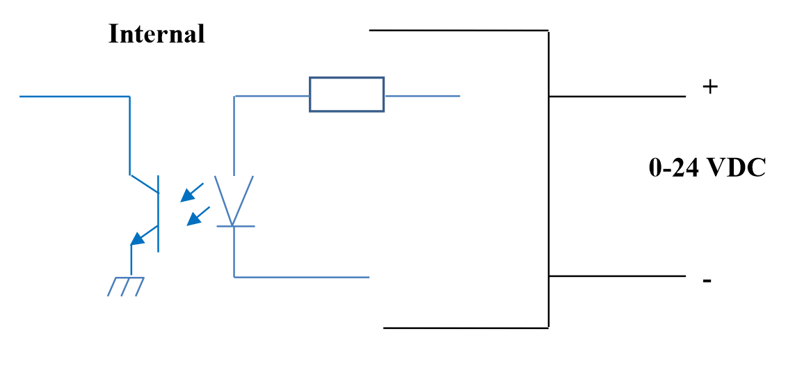
Specification:
- 04 channels DI, isolated
- Input Resistance: 4.7 kΏ
- Isolation Voltage: 5000Vrms
- Logic level 0: 0-1V
- Logic level 1: 5-24V
- Function:
- Read logic 0/1
- Pulse Counter
5.3.1 Read the logical state 0/1
Logic value in Modbus Memory Map: 0-1
Registers to store logic values in the Modbus Memory Map:
- DI1__DI2: digital status: stores the logical state of channel 1 and channel 2.
- H_byte: DI1
- L_byte: DI2
- DI3__DI4: digital status: store the logical state of channel 3 and channel 4.
- H_byte: DI3
- L_byte: DI4
5.3.2 Pulse Counter
Counter value in Modbus Memory Map, when adding the number exceeds the threshold, it will automatically return: 0 - 4294967295 (32bits)
The register that stores Counter value in the Modbus Memory Map can be erased:
- Counter DI1: stores the logic state of channel 1
- Counter DI2: stores the logic state of channel 2
- Counter DI3: stores the logic state of channel 3
- Counter DI4: stores the logic state of channel 4
The register that stores Counter value in the Modbus Memory Map cannot be erased:
- None reset counter DI1: stores the logic state of channel 1
- None reset counter DI2: stores the logic state of channel 2
- None reset counter DI3: stores the logic state of channel 3
- None reset counter DI4: stores the logic state of channel 4
Configura max number:
- "counter DI1: max number" : Count limit of counter, when counting to max value, counter will return to 0
- "counter DI2: max number" : Count limit of counter, when counting to max value, counter will return to 0
- "counter DI3: max number" : Count limit of counter, when counting to max value, counter will return to 0
- "counter DI4: max number" : Count limit of counter, when counting to max value, counter will return to 0
Pulse Counter Mode:
Low-speed pulse count less than 10Hz with filter, anti-jamming:
- Set register "counter DI1: filter time" = 500-2000: Channel 1 counts pulses less than 10Hz
- Set register "counter DI2: filter time" = 500-2000: Channel 2 counts pulses less than 10Hz
- Set register "counter DI3: filter time" = 500-2000: Channel 3 counts pulses less than 10Hz
- Set register "counter DI4: filter time" = 500-2000: Channel 4 counts pulses less than 10Hz
High-speed pulse count with max 2KHz frequency without filter:
- Set register "counter DI1: filter time" = 1: channel 1 counts pulses with Fmax = 2kHz
- Set register "counter DI2: filter time" = 1: channel 2 counts pulses with Fmax = 2kHz
- Set register "counter DI3: filter time" = 1: channel 3 counts pulses with Fmax = 2kHz
- Set register "counter DI4: filter time" = 1: channel 4 counts pulses with Fmax = 2kHz
5.3.3 Time on - Time off
Time on
DI1: time on = Total time DI1 at logic 1
DI2: time on = Total time DI2 at logic 1
DI3: time on = Total time DI3 at logic 1
DI4: time on = Total time DI4 at logic 1
Time off
DI1: time off = Total time DI1 at logic 0
DI2: time off = Total time DI2 at logic 0
DI3: time off = Total time DI3 at logic 0
DI4: time off = Total time DI4 at logic 0
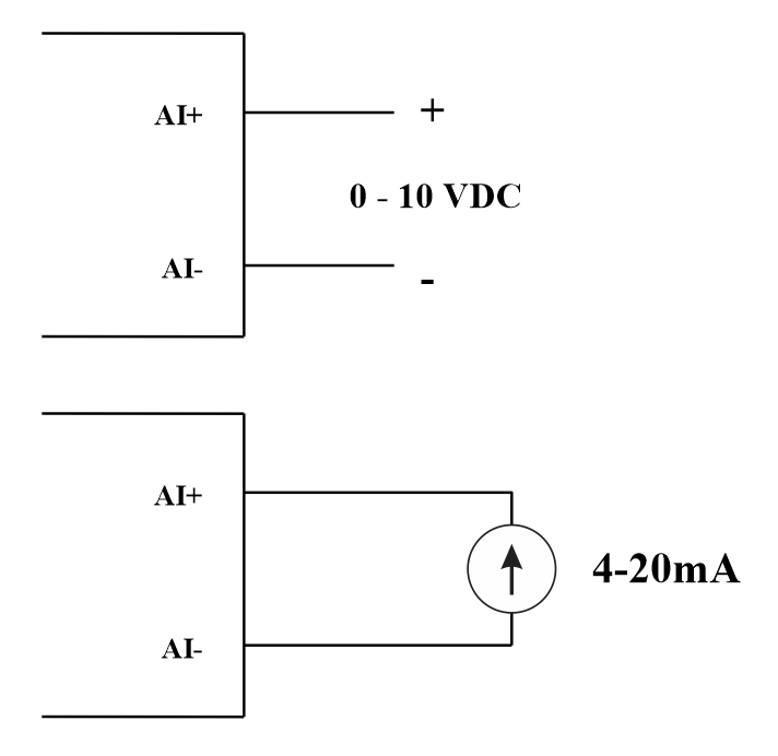
5.4 Analog Input
04 AI channels, no isolation
Use DIP SW to configure Analog input: 0-10V, 0-20mA
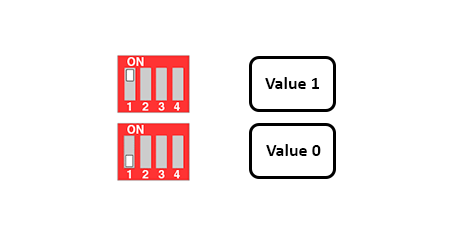
| Value | Type of AI |
| 0 |
0-10 V |
| 1 |
0-20 mA |
Input type:
- Measure voltage: 0-10V
- Measure current: 0-20mA
- The configuration for AI reads the same logical state as DI, but it is not isolated with a pulse range of 0-24V
Input impedance:
- Measure voltage: 320 kΏ
- Measure the current: 499 Ώ
5.4.1 Read the Analog value
Resolution 12 bits
Non-Linearity: 0.1%
Analog value in Modbus Memory Map: 0-3900
Analog value register in the Modbus Memory Map:
- AI1 analog value: store the Analog value of channel 1
- AI2 analog value: stores the Analog value of channel 2
- AI3 analog value: store the Analog value of channel 3
- AI4 analog value: store the Analog value of channel 4
5.4.2 AI configuration works as DI
No isolation
AI Configure AI to read the same logic state as DI with pulse amplitude from 0-24V
There are 2 counter threshold AIx: logic threshold 0 and counter AIx: threshold logic 1 in the modbus table: 0-4095
- Analog Analog value of AI <counter AIx: threshold logic 0: is considered Logic 0 status of AI
- Analog Analog value of AI> counter AIx: threshold logic 1: is considered to be Logic 1 state of AI
- Counter AIx: threshold logic 0 = <Analog value of AI <= counter AIx: threshold logic 1: is considered to be the constant logic state
Logic Logical status value of AI in Modbus Memory Map table: 0-1
The register stores logical values in Modbus Memory Map:
- AI1___AI2: digital status: stores the logical state of channel 1 and channel 2.
-
- H_byte: AI1
- L_byte: AI2
-
- AI3___AI4: digital status: stores the logical state of channel 1 and channel 2.
-
- H_byte: AI3
- L_byte: AI4
-
5.4.3 Pulse Counter AI max 10Hz
Counter value in Modbus Memory Map, when adding the number beyond the threshold, it will automatically return: 0 - 4294967295 (32bits)
The register that stores Counter value in the Modbus Memory Map can be erased:
- Counter AI1: stores the logic state of channel 1
- Counter AI2: stores the logic state of channel 2
- Counter AI3: stores the logic state of channel 3
- Counter AI4: stores the logic state of channel 4
The register that stores Counter value in the Modbus Memory Map cannot be erased:
- None reset counter AI1: stores the logic state of channel 1
- None reset counter AI2: stores the logic state of channel 2
- None reset counter AI3: stores the logic state of channel 3
- None reset counter AI4: stores the logic state of channel 4
Configura max number:
- "counter AI1: max number" : Count limit of counter, when counting to max value, counter will return to 0
- "counter AI2: max number" : Count limit of counter, when counting to max value, counter will return to 0
- "counter AI3: max number" : Count limit of counter, when counting to max value, counter will return to 0
- "counter AI4: max number" : Count limit of counter, when counting to max value, counter will return to 0
5.4.3 Time on - Time off
Time on
AI1: time on = Total time AI1 at logic 1
AI2: time on = Total time AI2 at logic 1
AI3: time on = Total time AI3 at logic 1
AI4: time on = Total time AI4 at logic 1
Time off
AI1: time off = Total time AI1 at logic 0
AI2: time off = Total time AI2 at logic 0
AI3: time off = Total time AI3 at logic 0
AI4: time off = Total time AI4 at logic 0
5.5 Relay
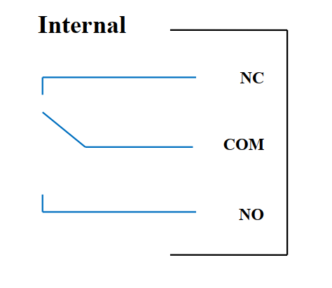
04 channel Relay SPDT NO / NC
Contact rating: 2A / 24VDC, 0.5A / 220VAC
There are status LEDs:
- Led on: Close Contact
- Led off: Open Contact
Set the "relay x" register in the Modbus Memory Map table to control Relay Close / Open Contact:
| Relay | Set Relay Register | Status of relays |
| Channel 1 |
1 | Close Contact |
| 0 | Open Contact | |
| Channel 2 |
1 | Close Contact |
| 0 | Open Contact | |
| Channel 3 |
1 | Close Contact |
| 0 | Open Contact | |
| Channel 4 |
1 | Close Contact |
| 0 | Open Contact |
Relay has 2 modes:
- Latch Mode
- Normal Mode
5.5.1 Latch Mode of Relay
The relay will remember the previous Close / Open Contact status, when resetting or losing power:
| Relay Channel | Relay Register | Set Relay Register | Description |
| Channel 1 |
relay default 1 | 2 | Relay channel 1 remembers the previous Close / Open Contact status |
| 0/1 | Relay channel 1 status does not remember the Close / Open Contact | ||
| Channel 2 |
relay default 2 | 2 | Relay channel 2 remembers the previous Close / Open Contact status |
| 0/1 | Relay channel 2 status does not remember the Close / Open Contact | ||
| Channel 3 |
relay default 3 | 2 | Relay channel 3 remembers the previous Close / Open Contact status |
| 0/1 | Relay channel 3 status does not remember the Close / Open Contact | ||
| Channel 4 |
relay default 4 | 2 | Relay channel 4 remembers the previous Close / Open Contact status |
| 0/1 | Relay channel 4 status does not remember the Close / Open Contact |
5.5.2 Normal Mode of Relay
Relay operates normally, do not remember the status of Close / Open Contact when power reset or power failure. Relay status table when resetting the power as follows:
| Register Default Relay | Status of relays when resetting power |
| 0 | Open Contact |
| 1 | Close Contact |
| 2 | Remember the previous state (Latch mode) |
5.6 Pulse Output
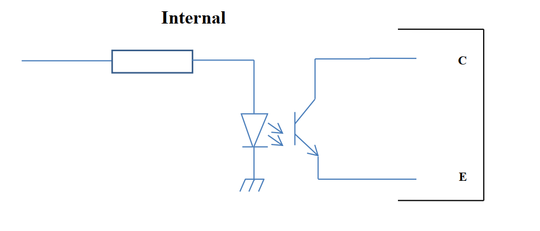
01 isolated open-collector channel
Opto-coupler: Source current Imax = 10mA, Vceo = 80V
Functions: On / Off, pulse generator, PWM
5.6.1 On/Off Function
Set the Open-collector register in the Modbus Memory Map table:
- Set Open-collector register: 1 => Pulse Output ON
- Set Open-collector register: 0 => Pulse Output OFF
5.6.2 Pulse generator
Pulse output transmits a maximum of 65535 pulses, with Fmax 2.5kHz
Configure the following registers in the Modbus Memory Map table:
- Set register "open collector: pulse number": 0-65535 => Pulse Number = 65535: broadcast 65535 pulses
- Set register "open collector: time cycle": (0-65535) x0.1ms => Time Cycle = 4: Fmax 2.5kHz
- Set register "open collector: time on": (0-65535) x0.1ms => Time On: is the logic time 1 of the pulse
- Set the register "open collector ctrl" = 3 => configure the Pulse Output to generate a pulse and start to pulse, generate a sufficient number of pulses in the "open collector: pulse number" register => stop pulse generator and register " open collector ctrl ”= 0
5.6.3 PWM
Max frequency 2.5kHz
Configure the following registers in the Modbus Memory Map table:
- Set the register "open collector ctrl" = 2 => configure Pulse Output PWM function
- Set register "open collector: time cycle": (0-65535) x0.1ms => Time Cycle = 4: Fmax 2.5kHz
- Set register "open collector: time on": (0-65535) x0.1ms => Time On: is the logic time 1 of the pulse
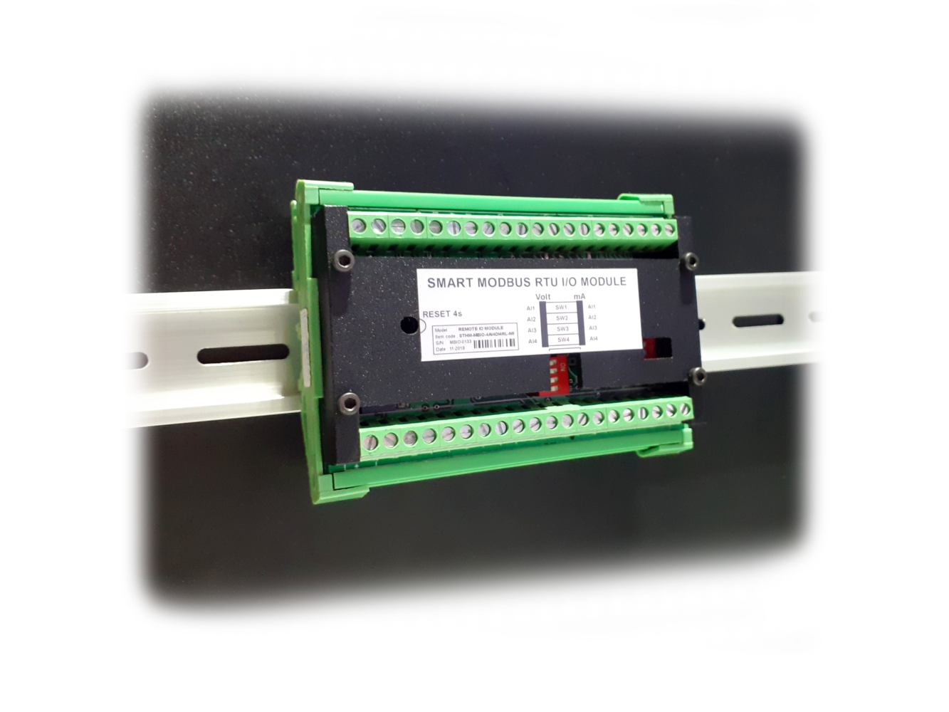
6. Installation
Mounting type: DIN rail
7. Troubleshooting
| No. | Phenomena | Reason | Solutions |
| 1 | Modbus failed to communicate |
Modbus LED Status:
|
|
| 2 | Timeout Modbus | Noise appears on the line | Configure Baudrate 9600 and use a twisted pair cable with anti-jamming protection |
8. Support contacts
|
Manufacturer Daviteq Technologies Inc
No.11 Street 2G, Nam Hung Vuong Res., An Lac Ward, Binh Tan Dist., Ho Chi Minh City, Vietnam. Email: info@daviteq.com | www.daviteq.com |
No Comments