USER GUIDE FOR SUBMERSIBLE LIQUID LEVEL TRANSMITTER LEET-M
| LEET-M-MN-EN-01 |
FEB-2020 |
This document is applied for the following products
|
SKU |
LEET-M |
HW Ver. |
1.0 |
FW Ver. |
1.0 |
|
Item Code |
LEET-M-01-001-SS-PE-FL |
LEET-M submersible level transmitter, 316L SS diaphragm, PE cable, flying leads, 1mH20 FS |
|||
|
LEET-M-01-001-SS-PU-FL |
LEET-M submersible level transmitter, 316L SS diaphragm, PU cable, flying leads, 1mH20 FS |
||||
|
LEET-M-01-001-TL-PE-FL |
LEET-M submersible level transmitter, Tantalum diaphragm, PE cable, flying leads, 1mH20 FS |
||||
|
LEET-M-01-001-TL-PU-FL |
LEET-M submersible level transmitter, Tantalum diaphragm, PU cable, flying leads, 1mH20 FS |
||||
| LEET-M-01-001-SS-PE-M12 |
LEET-M submersible level transmitter, 316L SS diaphragm, PE cable, M12-F connector, 1mH20 FS |
||||
|
LEET-M-01-001-SS-PU-M12 |
LEET-M submersible level transmitter, 316L SS diaphragm, PU cable, M12-F connector, 1mH20 FS |
||||
|
LEET-M-01-001-TL-PE-M12 |
LEET-M submersible level transmitter, Tantalum diaphragm, PE cable, M12-F connector, 1mH20 FS |
||||
|
LEET-M-01-001-TL-PU-M12 |
LEET-M submersible level transmitter, Tantalum diaphragm, PU cable, M12-F connector, 1mH20 FS |
||||
1. Functions Change Log
| HW Ver.
|
FW Ver. |
Release Date |
Function Change |
|
1.0 |
1.0 |
FEB-2020 |
2. Introduction
LEET-M is a full sealed submersible level transmitter. It utilises the advanced piezo-resistive pressure sensor and high accurate measurement circuit to deliver high accuracy and very stable measurement. Integrated construction and standard signal provide the user easy and convenient installation for most applications. The special cable connects with housing, can be permanently immersed into the liquid for long time. LEET-M level transmitter has small size, light weight and good stability. It can be used for water or liquid measure and control of medicine, metallurgy, electricity, mine, city water supply and drainage, etc.
3. Specification
| Range(FS) | Select 1, 5, 10, 20, 50, 100, 200mH2O |
| Overpressure | 1.5 times FS |
| Accuracy | Range ≤ 50mH2O, accuracy +/-1.0% FS. Range > 50 mH2O, accuracy +/- 0.5% FS |
| Stability | Range > 10mH2O, ±0.2%FS/year. Range ≤ 10mH2O, 20mmH2O/year |
| Thermal drift | Range > 10mH2O, ±0.02%FS/℃. Range ≤ 10mH2O, ±0.05%FS/℃ |
| Working temperature | -10℃~70℃, -10℃~60℃(Ex ia) |
| Storage temperature | -20℃~85℃ |
| Power supply | 11V~28VDC |
| Output signal | 4mA~20mADC(2-wire, loop powered) |
| Load | ≤(U-11)/0.02Ω |
| Housing | Stainless steel 1Cr18Ni9Ti |
| Diaphragm | Stainless steel 316L as standard, optional Tantalum |
| Cable material | φ7.5mm Polyethylene cable as standard, Optional Polyurethane cable |
| Cable length | 2M additional of FS |
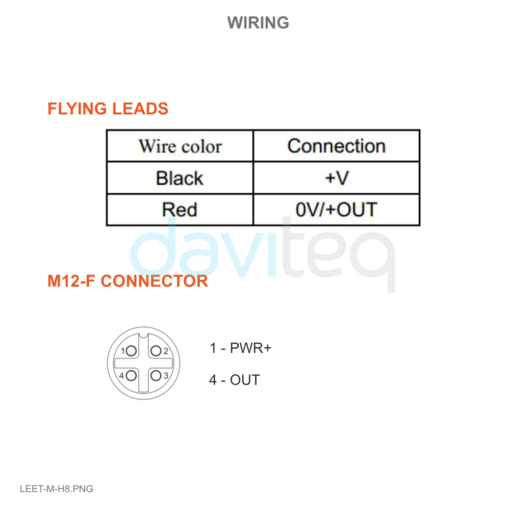
| Connector | No connector - flying leads as standard, optional M12-F connector |
| Ex approval | Optional ATEX Ex ia ⅡC T6 |
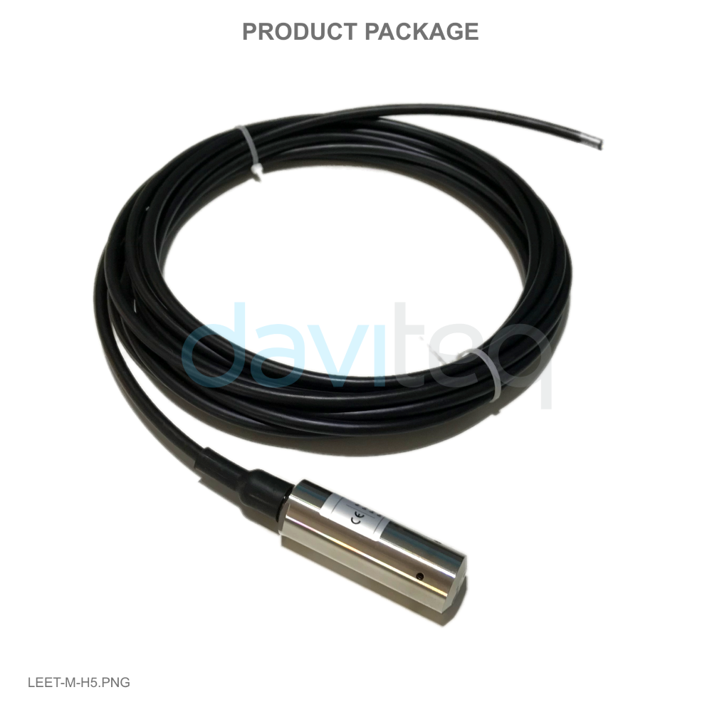
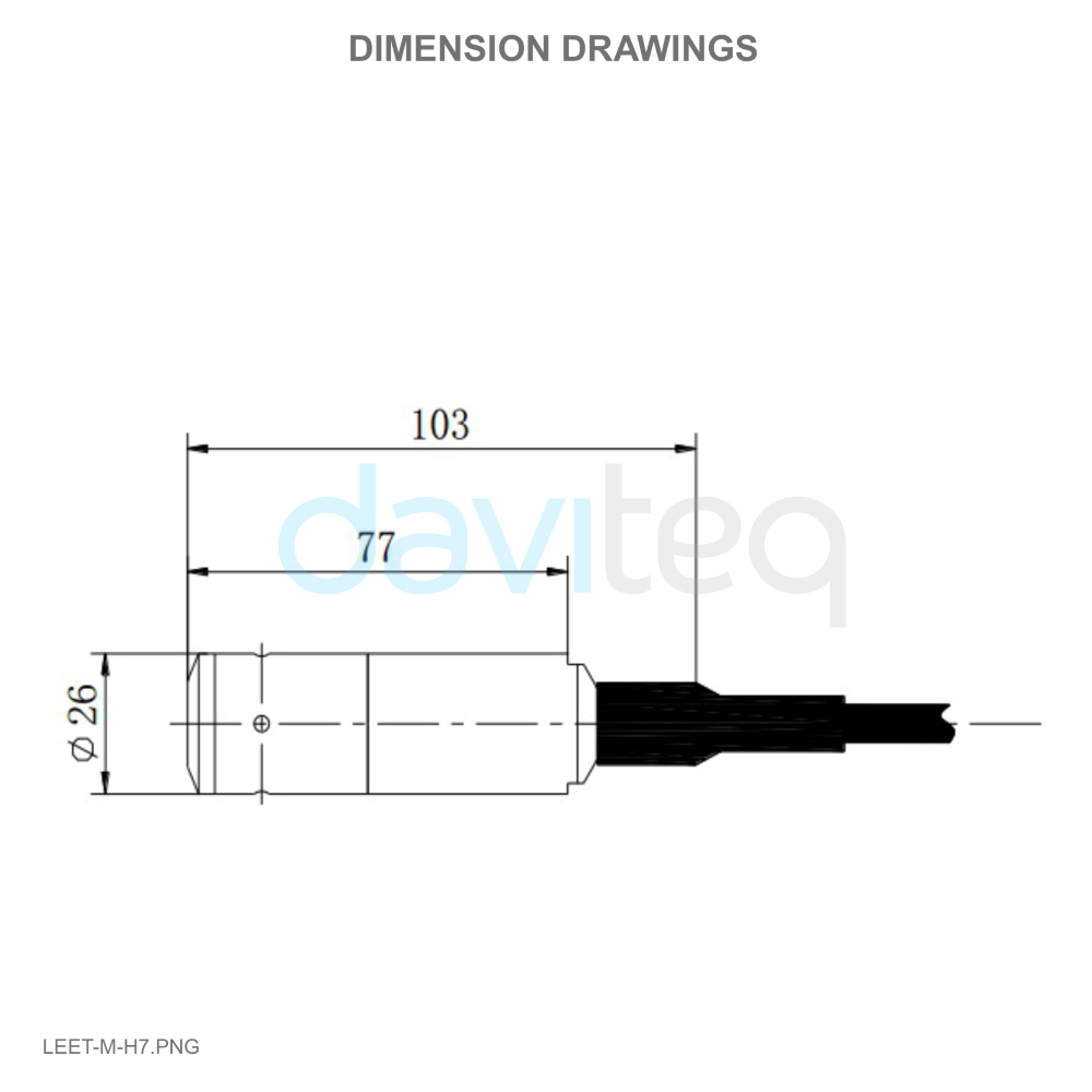
4. Product Pictures
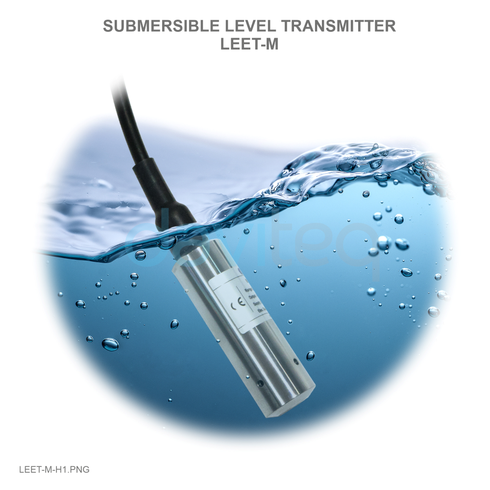 |
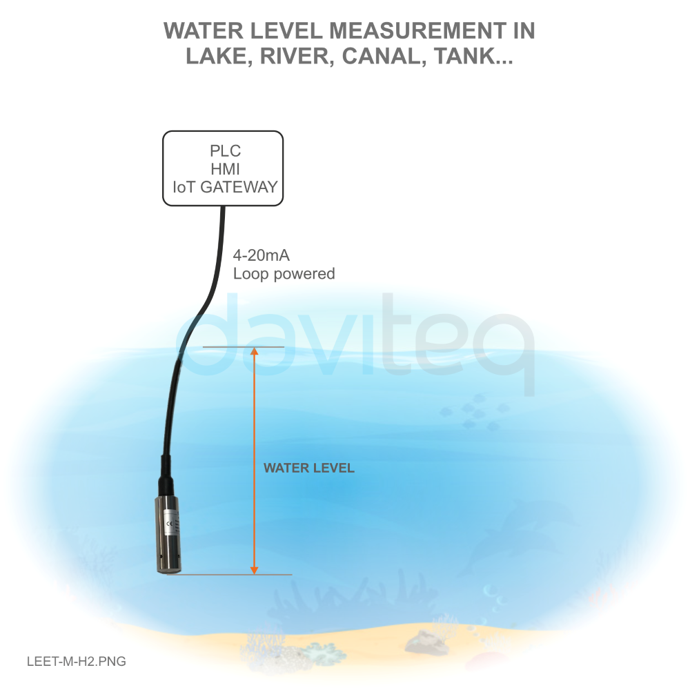 |
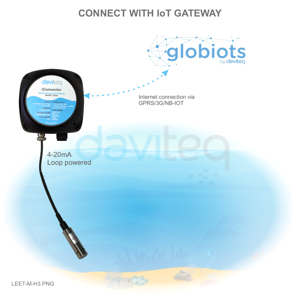 |
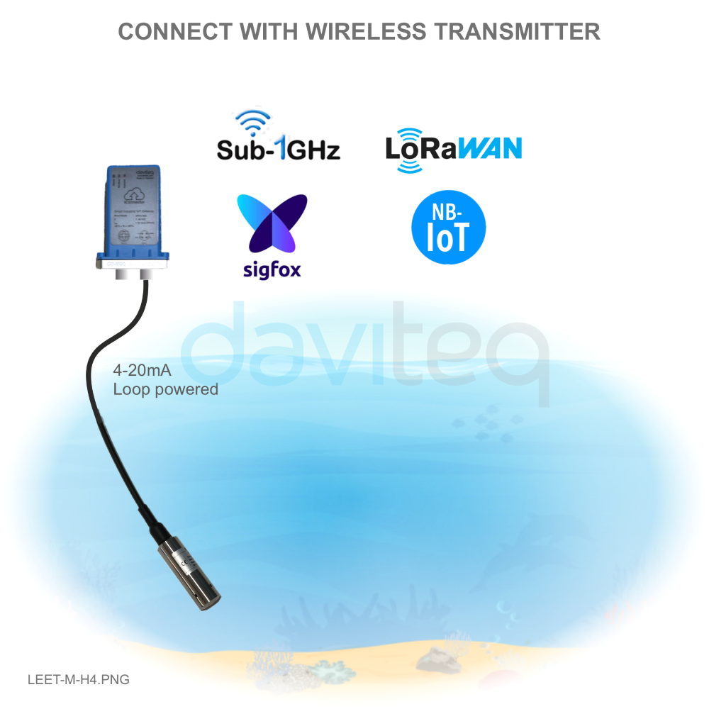 |
 |
 |
 |
 |
5. Operation Principle
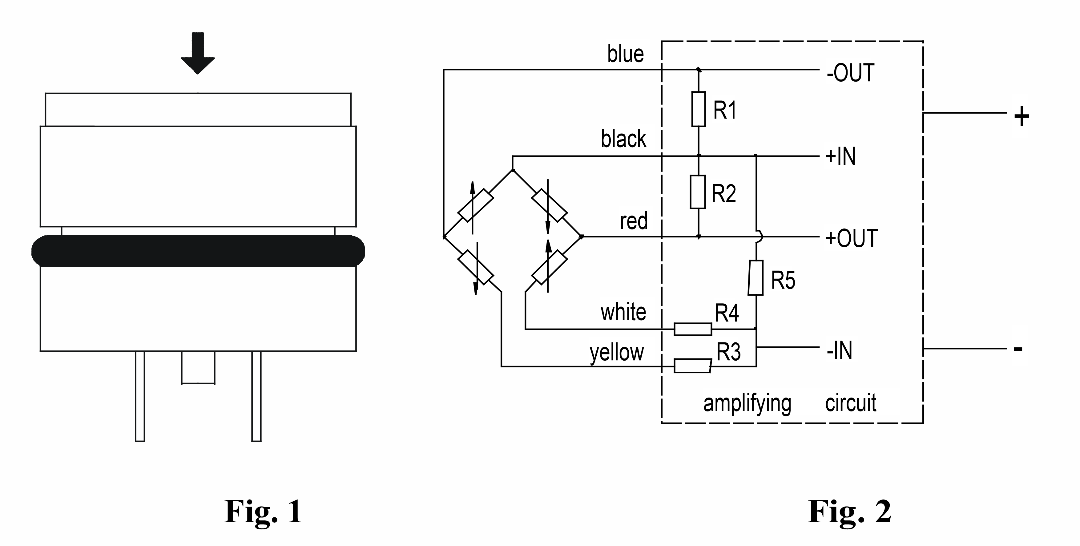
The measuring element of transmitter is a sensor, which transfers the pressure into electric signal by semiconductor silicon material’s piezo-resistive effect. The measured pressure acts on stainless steel diaphragm, and then be transferred onto sensitive chip by silicon oil which is filled between the stainless steel diaphragm and sensitive chip (see Fig. 1). The sensitive chip is connected with transmitter special amplifying circuit by wires (see Fig. 2). Due to the good linearity relationship between the electric signal of Wheatstone bridge on the sensitive chip and the measured pressure, the pressure could be measured accurately.
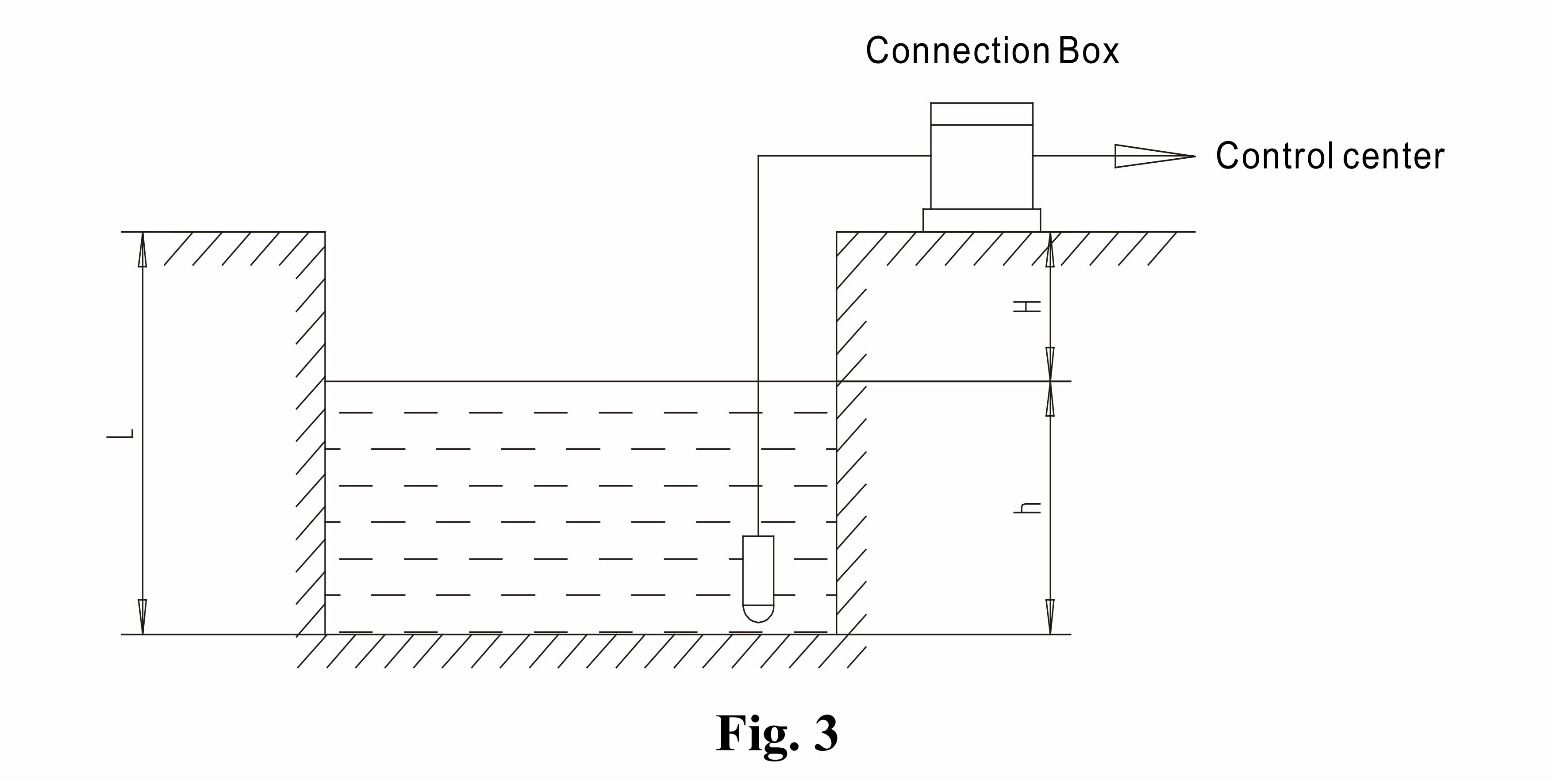
The basic principle of level measurement is that the liquid static pressure which proportioned with the liquid depth is transferred into current (or voltage) signal output, and establishing the linearity corresponding relationship between electric signal output and the liquid depth to measure level or the liquid depth. The level measurement principle of transmitter to see Fig. 3:
P = γ. h……………….①
P is the liquid static pressure at the measuring point;
γ is the liquid specific gravity;
h is the depth from the measuring point to the liquid surface, or level.
Calculation Examples:
Use a level transmitter with pressure range 10mH2O, 2-wire, 4mA~20mADC output to measure the level of some pool, the water gravity is 1.0. If the output is 10mA, what is the measured level?
Solution: I = 4 + K•P …………..②
Put formula ① P = γ·h into formula ②:
I = 4 + K·h·γ…………③
I is the output current value, the unit is mA;
4 is the zero output of transmitter, 4mA;
K is the transmitter sensitivity, or the ratio of transmitter FS output( this example is 20-4 = 16mA) to range(this example is 10mH2O. For this example, 16mA/10mH2O = 1.6 (mA/mH2O). This value has been given in product qualify certificate.
h is the level, the unit is m;
γ is the liquid gravity, this example is 1.0;
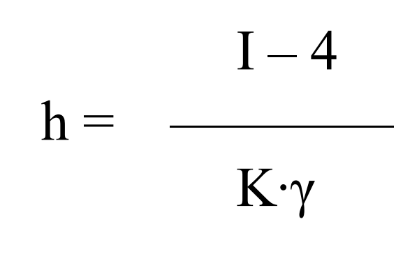
From formula ③, we get:
Put all the values into formula ④, we have
The measuring result is five meters
6. Configuration
- The customer could operate the transmitter without adjustment.
- Please be sure that the installation and electrical connection are correct or not before operation.
- Connect the excitation and operate.
- The transmitter could work at once as soon as it is connected with excitation, but the output signal could be more reliable after 30 minutes
7. Installation
Attention before transmitter installation:
- The transmitter should be stored in dry and ventilation room with ambient temperature -40℃ ~100℃, relative humidity no more than 85% and the air in the room without corrosive gas.
- The static pressure produced by the liquid at installation place exceeds the transmitter FS or not.
- The measuring liquid is compatible with the transmitter construction material or not.
- The measuring liquid may stop up the holes on the protection cap or not.
-
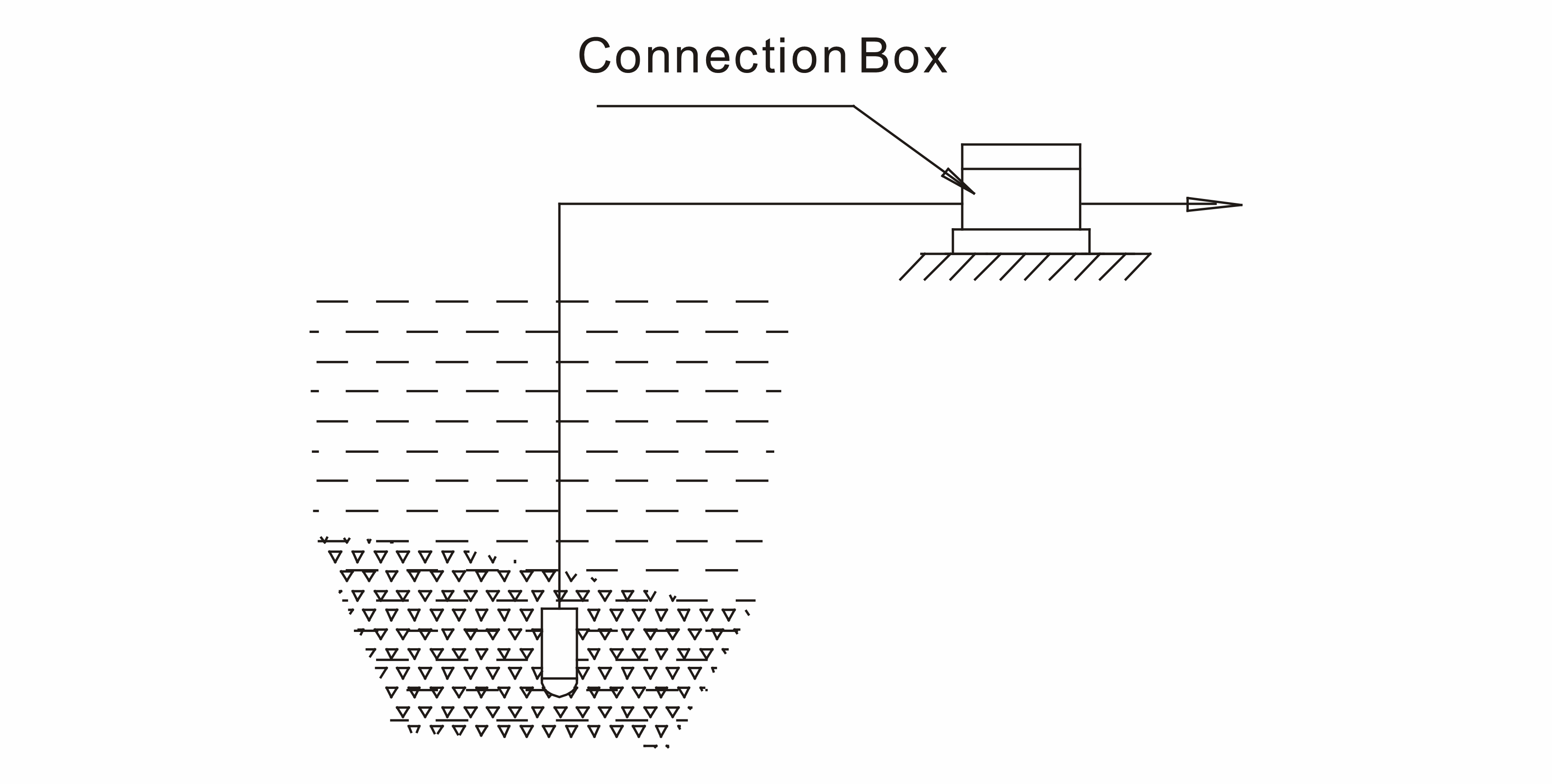
The transmitter should be installed vertically down.
-
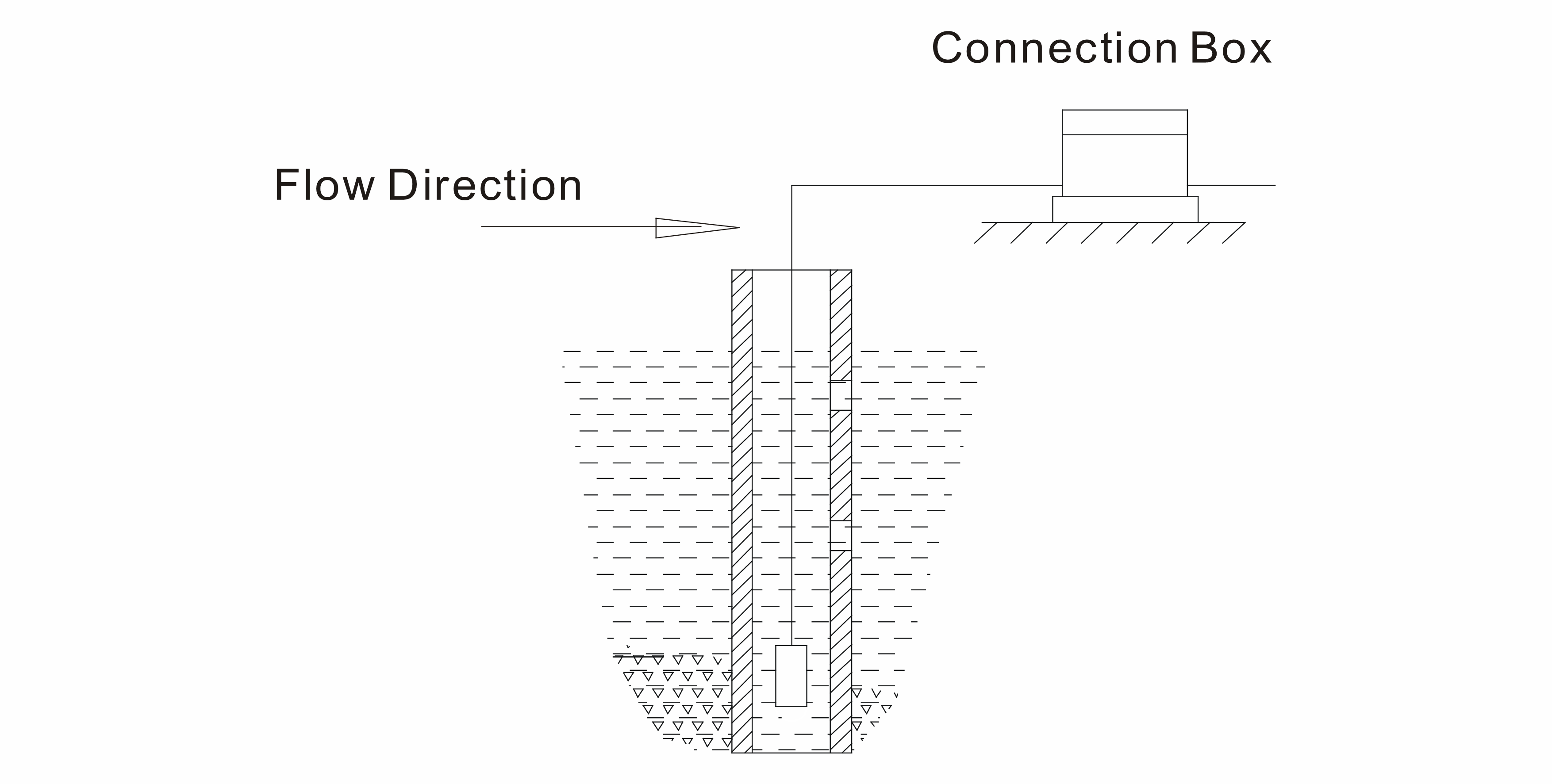
In the flowing water, the acted surface should be parallel with the water flowing direction.
7.1 Installation in the Static Water
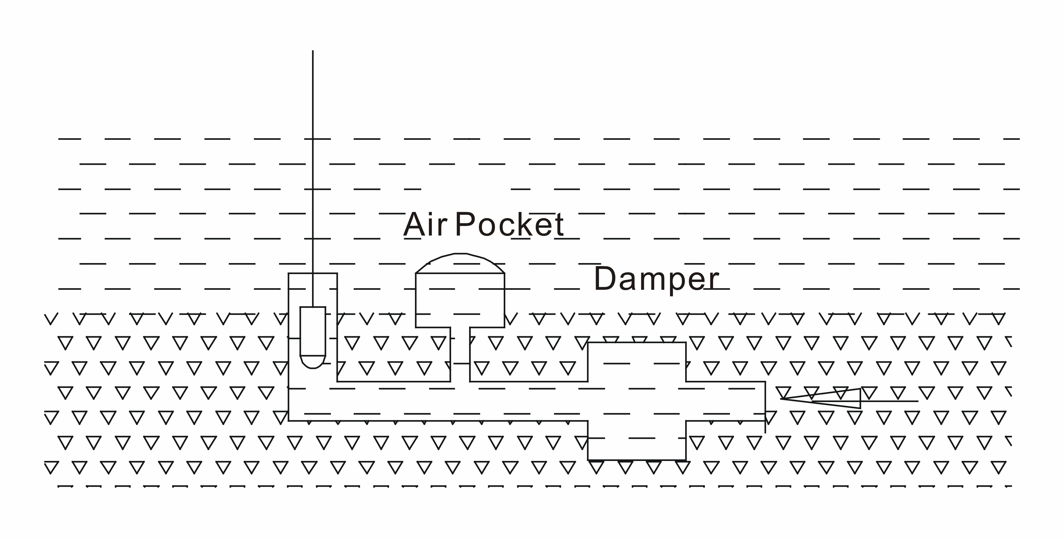
7.2 Installation in the Flowing Water
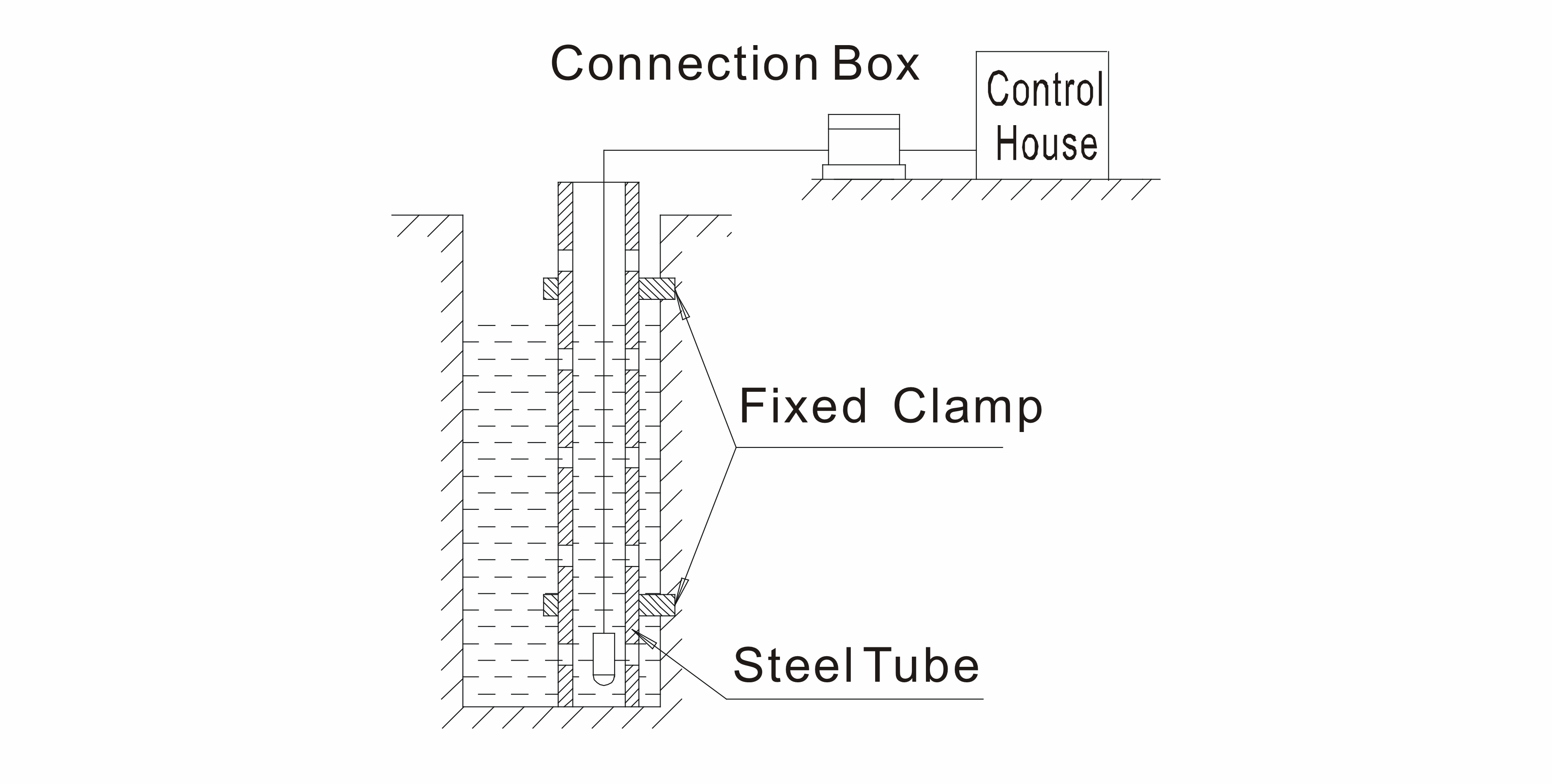
The water-calming equipments are required.
a. Insert a steel tube in the water channel
The steel tube wall should be thicker, and several holes should be made at different heights on the tube to damp waves and clear the water pressure influence.
b. Superficial burying is better in the sand and stone channel
c. This method can not only clear water flowing pressure and wave influence, but also filter the sand and mud.
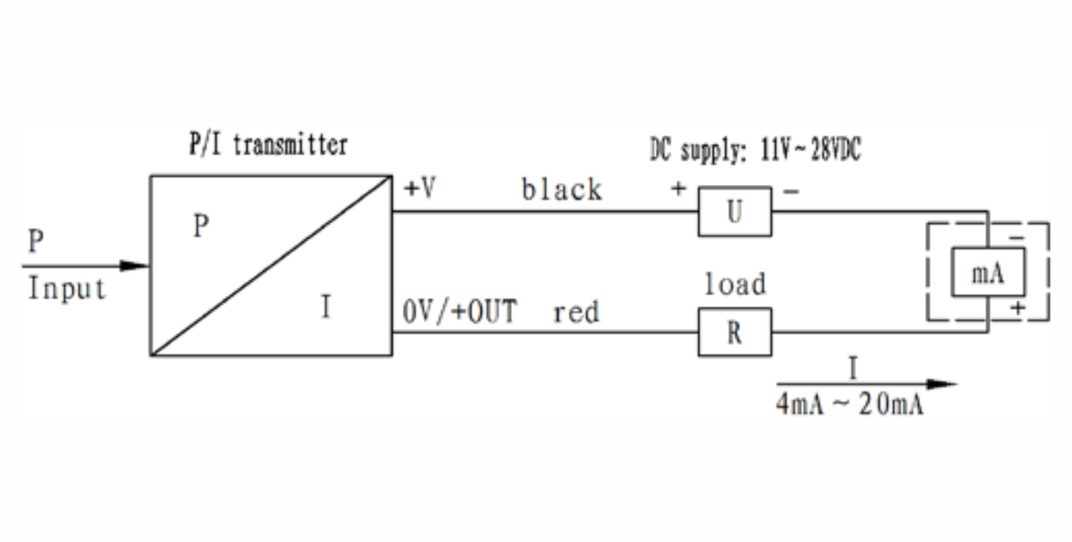
7.3 Electrical Connection
Electrical connection method of transmitter with Two-wire 4mA~20mA DC output
7.4 The Reference Tube Installation
There is a plastic tube in the transmitter special cable; the back pressure cavity of gauge sensor is connected to atmosphere by this tube. In the process of installation and operation, be sure to keep the reference tube be well connected with the atmosphere. Mud or sand should not be jammed into the reference tube.
Prevent water or other liquid going through the reference tube to destroy the transmitter.
7.5 Maintenence
LEET-M level transmitter does not need to be maintained regularly, but please pay attention to items as follow for better operating effect and reliability.
Check wire connection is reliable or not, and the cable is broken and old or not.
Clean the protection cap and diaphragm cavity periodically. BE CAREFUL!
Don’t violently pull cables or poke the diaphragm with metal or other hard objects.
8. Troubleshooting
LEET-M level transmitter is integrative full-sealed construction without movable parts inside, owning advantage of long-term stability and reliability.
If some failure occur, such as no output, output too big or too small and unreliable, please turn off the excitation firstly, then check the installation and wire connection conform with the operation manual or not, the excitation is correct or not and the reference tube is unobstructed or not.
If unsuccessful, the transmitter may be destroyed, please contact our company.
9. Support contacts:
|
Manufacturer Daviteq Technologies Inc Email: info@daviteq.com | www.daviteq.com
|
Distributor in Australia and New Zealand Templogger Pty Ltd Tel: 1800 LOGGER Email: contact@templogger.net |




No Comments