Panel mount Industrial IoT HMI
| PHMI-MN-EN-01 |
NOV-2025 |
This document is applied for the following products
| SKU | PHMI | HW Ver. | 1H | FW Ver. | 1F1118 |
| Item Code |
PHMI-10-01 |
Industrial IoT HMI for panel mount, LCD display,10-inch touchscreen; |
|||
1. Functions Change Log
| HW Ver. | FW Ver. | Release Date | Functions Change |
| 1H | 1F1118 | Nov-2025 |
Initial firmware |
2. Introduction
PHMI is an all-in-one industrial HMI device that functions as both a user-friendly interface and an intelligent gateway for Industrial IoT applications. Featuring a 10.1" or 8" IPS LCD multi-touch display, it comes with standard interfaces such as Ethernet, RS485, and USB, along with optional wireless connectivity including WiFi, 4G, and 5G for seamless integration with cloud platforms and IoT systems.
The device is programmable via Node-Red, enabling fast deployment of customized HMI applications. It also supports optional expansions such as a 433 MHz Wireless Concentrator for WS433 sensors, BLE for MESH sensor networks, and a built-in LoRaWAN Gateway for wide-area sensor networks.
With powerful features and flexible architecture, PHMI is the ideal solution for Smart Factory, Smart Building, and Smart Agriculture applications.
3. Specification
| Standard Communication | 01 x RS485, 01 x USB, 01 x RJ45 Ethernet and Wifi |
| Optional Communication | 4G or 5G, BLE, LoRaWAN Gateway, WS433 Sub-GHz Co-ordinator |
| Protocol support | ModbusRTU/ASCII, ModbusTCP, BacnetIP, OPC-UA, EthernetIP, MQTT, HTTP... |
| Screen type | 10.1" 1290x800 colour IPS LCD Display with capacitive touch screen |
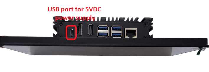
| Power supply | 5VDC via USB type C port. Included power adapter with input of 100-240VAC and output USB type C 5VDC max 5A |
| Consumption | 500mA avg. |
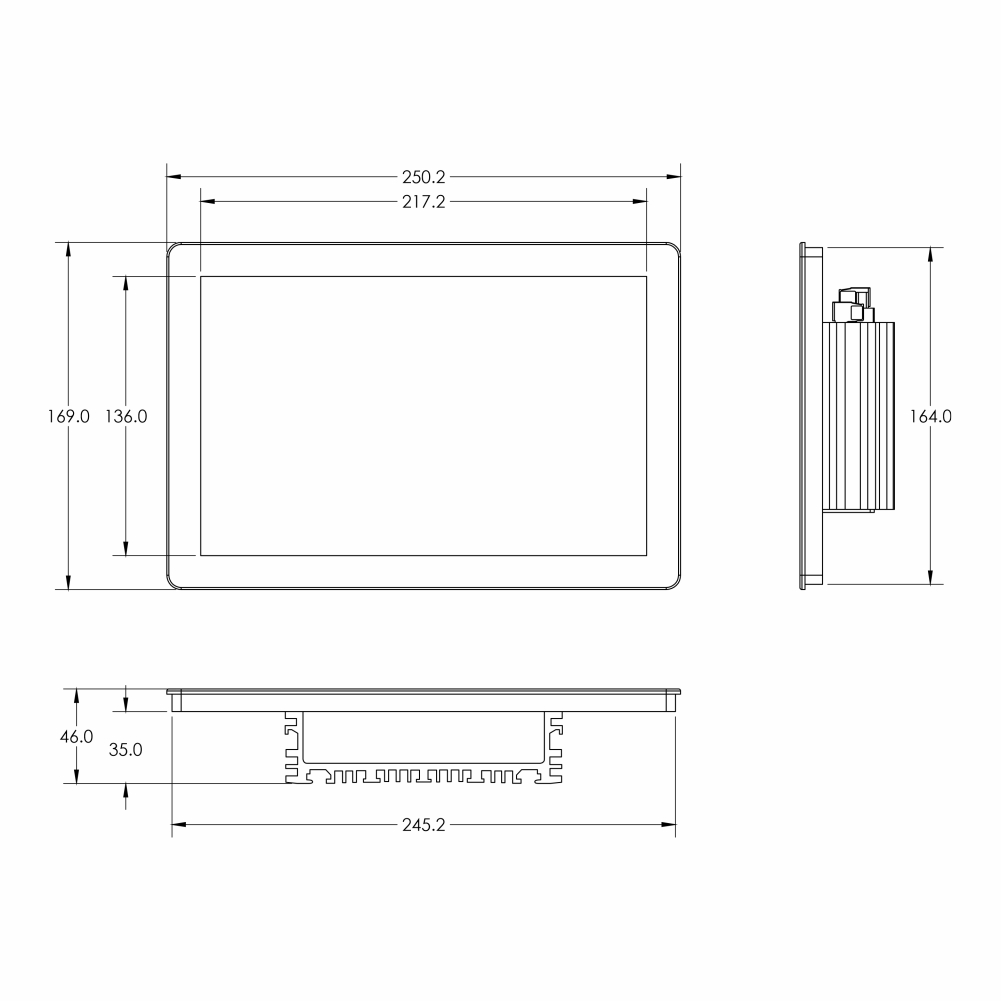
| Mounting type | Panel mount 246x165 mm cut-out, VESA mount screws |
| Working temperature/humidity | 0..60 degC / 95%RH non-condensing |
| Dimension | H169xW250xD50 |
| Net weight | 750 grams.. |
4. Installation and wirings
4.1 Installation
Installation type: Panel mount
Installation steps:
Step 1: Based on HMI dimension, cut the rectangular hole on the panel
Step 2:
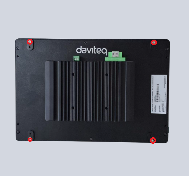
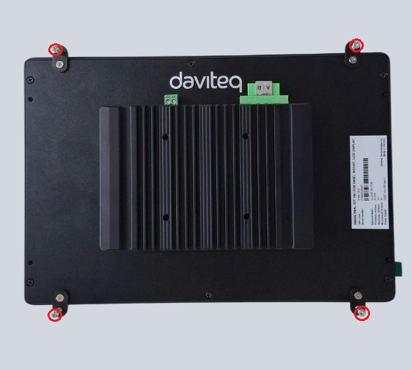
Use screw driver to loose 4 screws, then turn 4 batches 90 degree
Step 3:
Fix 4 batches to the panel by 4 provided bolts
4.2 Wiring
Power Supply:
5VDC via USB type C port. The product is provided with power adapter having input of 100-240VAC and output USB type C 5VDC max 5A
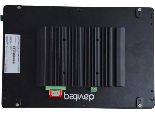
RS485 connection:
RS485+ of Modbus Master to A pin on HMI
RS485 - of Modbus Master to B pin on HMI
5. Operation principle
The HMI operates as Modbus slave device. The Modbus Master device will write real time values to HMI via RS485 Modbus RTU and HMI will show these values on HMI screens. The clock time on Modbus Master device also be written on HMI.
6. Configuration
HMI operate with Modbus RTU - slave communication via RS485 port as below fixed configurations:
Protocol: Modbus RTU
Address: 2
Baud rate: 9600
Parity: none
Stop bit: 1
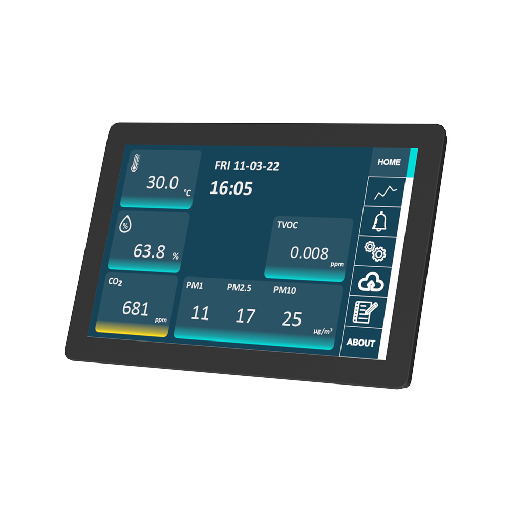
7. Graphic user interface
7.1 Home Screen
After power up, the HOME screen will show 5 rows x 4 columns = max 20 data from Modbus Masters
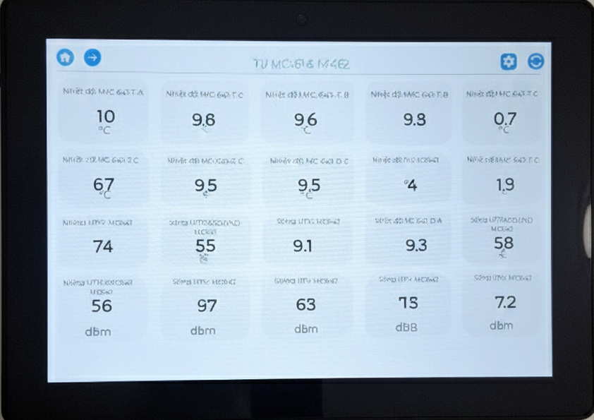
HOME icon: Click to return home page
LEFT ARROW icon: Click to move to next page
RIGHT ARROW icon: Click to move to previous page
REFRESH icon: Click to refresh data
7.2 Other screens
There are total four screens, click RIGH ARROW icon and LEFT ARROW icon to navigate screens and click HOME icon to return HOME screen. Each screen shows maximum 20 paramter values which are written from Modbus Master device
8. Support contacts
|
Manufacturer Daviteq Technologies Inc
No.11 Street 2G, Nam Hung Vuong Res., An Lac Ward, Binh Tan Dist., Ho Chi Minh City, Vietnam. Email: info@daviteq.com | www.daviteq.com |
No Comments