1. Quick installation guide for WSNBM-AQUA
This manual is applied to the following products:
| Item code | Hardware version | Firmware Version | Firmware released date | Change information |
|
WSNBM-AQUA-1G10-IA
WSNBM-AQUA-2G10-IA
|
1 | 1 | 10 June 2025 | Initial firmware |
1.1 Introduction
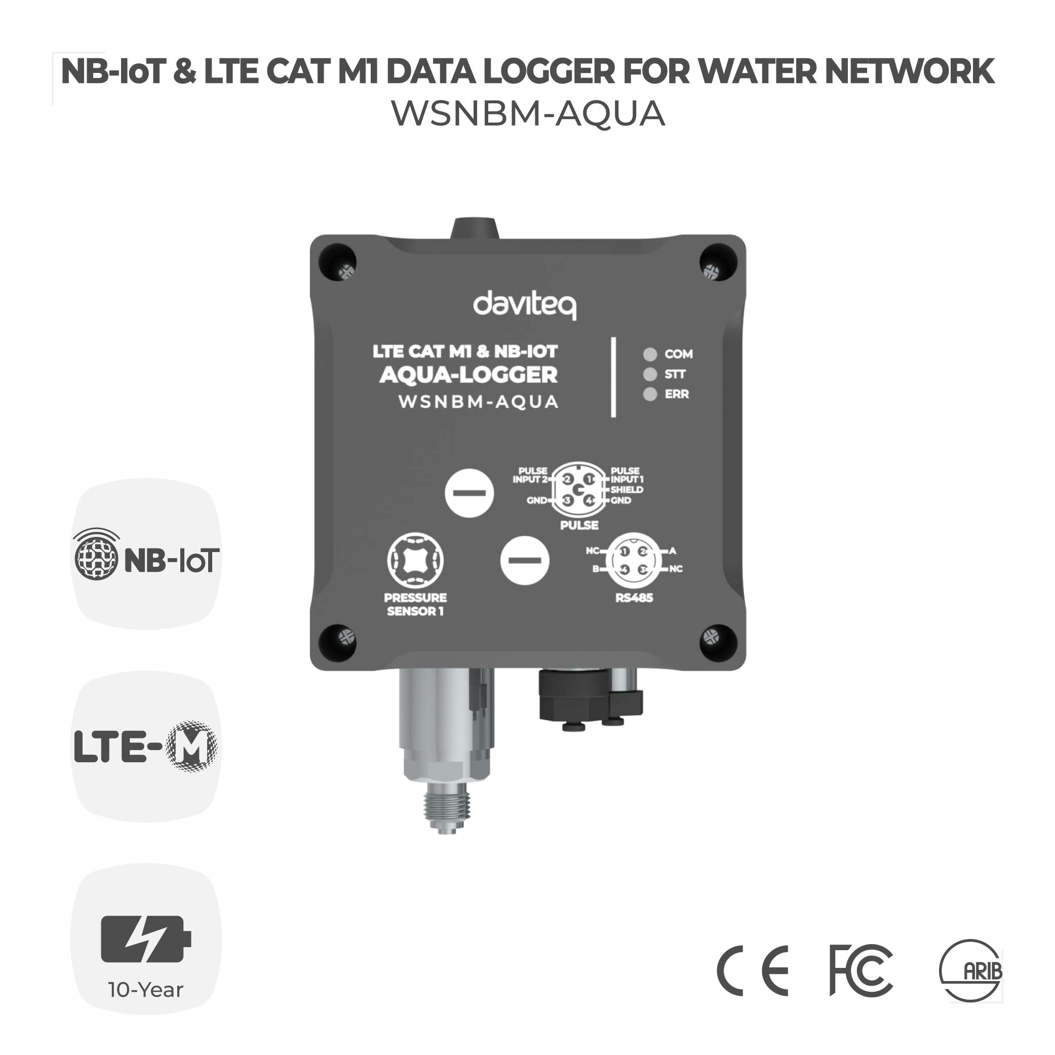
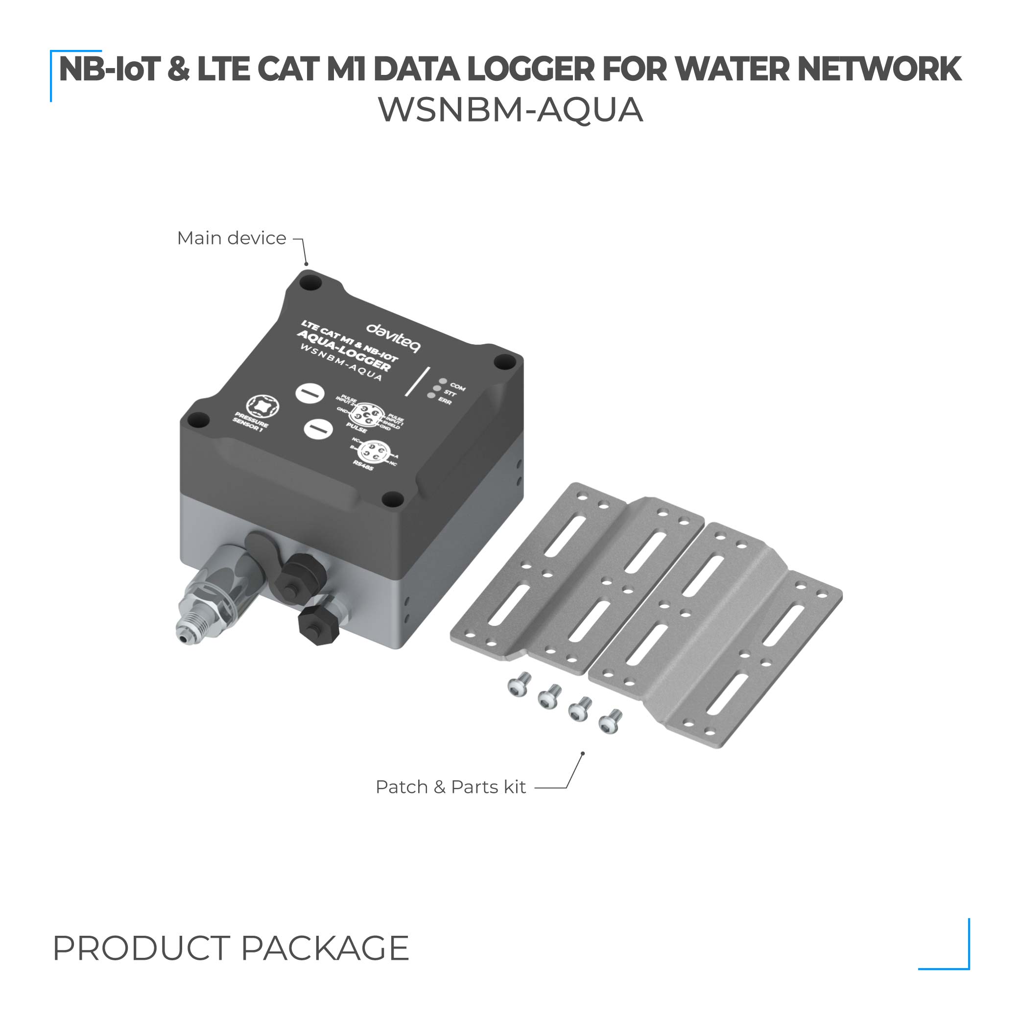
The WSNBM-AQUA is a cutting-edge NB-IoT and LTE Cat M1 data logger tailored for comprehensive water pipeline network monitoring. It includes pulse inputs, an RS485 Modbus RTU Master Node, and built-in pressure sensors. Designed for long-term performance, the device operates efficiently on one or two batteries, offering a lifespan of 5 to 10 years. With support for global frequency bands, it is an ideal solution for city water networks, industrial parks, smart utility systems, and various other applications.
1.1.1. The MQTT data logger system architecture
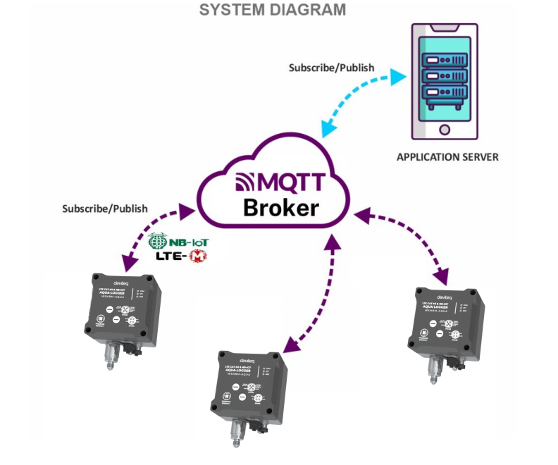
System components:
- Aqua logger: publish the the data messages to the broker and subscribe request of configuration change messages from the application
- MQTT broker: is the server that receives the data messages from the loggers then route them to the application. In addition, the broker also receives request of configuration change messages from the application and then route them to the logger
- MQTT application: subscribe the data messages from loggers and publish request of configuration change messages to the logger
1.1.2. How to set up the MQTT system?
Please follow these steps:
- Configure on MQTT broker: the user, password, QoS, CA file, SSL
- Configure on the logger: MQTT configurations (host, port, user, password, CA file, SSL on/off, QoS, message retain), CAT M1/NB-IoT configurations (network category, frequency bands, RAT search sequence)
- Configure on the application: host, port, user, password, QoS, CA file
- Insert the CAT M1/NB-IoT SIM to the logger, then insert the batteries/power supply. The logger will publish the messages to the MQTT broker and then the broker will route the messages to the application
1.2 When does device publish the topic?
The device will publish the topic following cases to MQTT brokers:
Case 1: When device is power-up, the device will publish the first topic called START_UP. The payload will tell the user the full device configurations and device health statuses.
Case 2: In every interval time (pre-configured), for example, 24 hours, it will publish the topic called HEARTBEAT. The payload will tell the user the full device configurations and device health statuses.
Case 3: If users want to get the value of device configurations and device health immediately, user could force the device to publish the CONFIG-HEALTH-CHECK topic. The device could be forced by applying the magnet key in more than 5s.
Case 4: During the commissioning, testing, or calibration logger, the user can force the device to publish the topic to get the data immediately. This topic is called FORCE. The payload will provide data like raw measured value, scaled measured values, and device health. It can be forced by applying the magnet key on the reed switch in 1s;
Case 5: Then, in every interval time (pre-configured), for example, 10 minutes, it will publish the topic called CYCLE. The payload will tell the user the following data like measured values and device health. To change the cycle of data sending, you can change the value of the CYCLE_PERIOD parameter.
Case 6 : If the application requests to change device configurations, the application will publish the CONFIG-REQUEST topic to the MQTT broker and the device subscribe the CONFIG-REQUEST topic. After that, the device will change the configuration as request in the CONFIG-REQUEST topic and publish CONFIG-RECEIPT topic. The payload of CONFIG-RECEIPT topic contains the result of the configuration changes.
1.3 Default Configuration
Please refer to the END USER DEFAULT column in the memory map file at the section 1.9 Payload Document and Configuration Tables
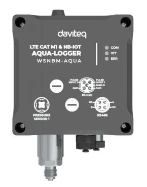
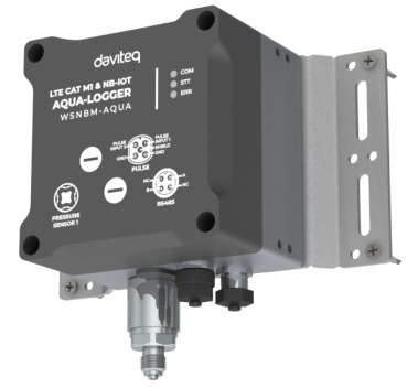
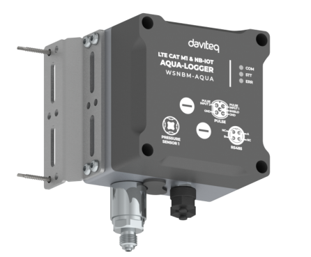
1.4 Hardware overview
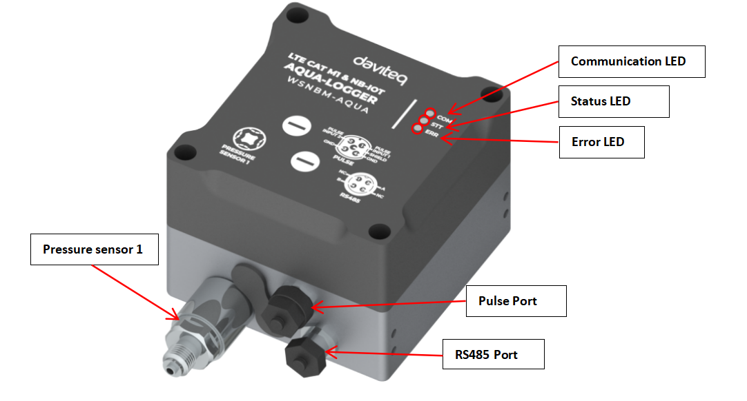
LED PRINCIPLE
| OFF | FLASHING | |
| COM LED (Red) | Power-off OR sleep status | Operation status (measurement/data sending) |
| STT LED (Red) | Configuration port-off | Configuration port -on |
| ERR LED (Red) | Power Off or No Error | Hardware Error |
1.5 Power supply
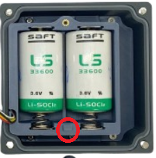
- Rechargeable battery:
-
Use 2 x D-size battery 3.6V LiSOCl2 with 17Ah;
Recommend to use SAFT LS33600 or equivalent from Tadiran.

Procedures to insert batteries
- Open the device upper housing by removing 4 screws
- Open the battery cover by removing a screw, then slide the cover upward slightly to move the cover out of the latch, then take out the cover
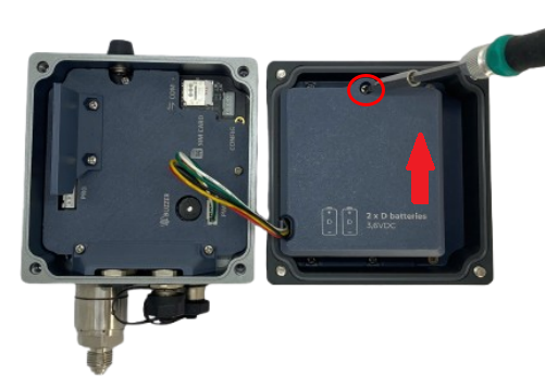
Note:
Hard slide the battery cover might result in broken the latch of the battery cover
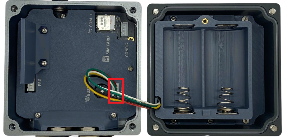
- Unplug power connector from the mainboard, and wait 5 minutes

- Insert batteries to the battery holder with right polarity
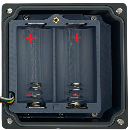
Note:
Wrong polarity might cause the device faulty
- Plug the power connector back
- Close the battery cover and device upper housing
1.6 What's in the Package?
1.7 Guide for Quick Test
- MQTT broker's settings: host, post, user, password CAT file (if applicable), QoS
- Cellular settings: CAT M1/NB IoT, frequency bands
Step 2: Configure on the logger the MQTT configurations (host, port, user, password, CA file, SSL on/off, QoS, message retain), CAT M1/NB-IoT configurations (network category, frequency bands, RAT search sequence) with offline tool and the template.
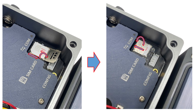
- Open the device upper housing by removing 4 screws
- Insert the SIM to the device: Push the SIM holder cover slightly, open the SIM holder cover, insert the SIM to the holder, then close the SIM holder cover and then push the SIM holder cover back to origin position.
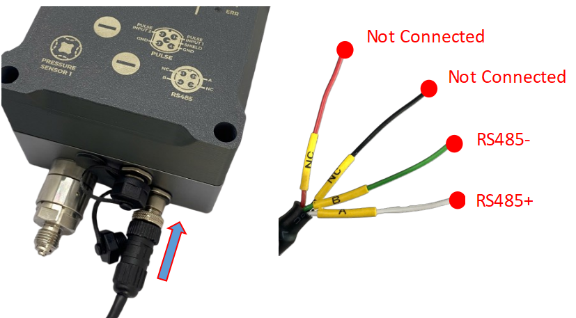
Step 4: Connect RS485 Modbus RTU device to the logger
RS485 + wire (A label) of the cable to RS485 + of Slave device/meter
RS485 - wire(B label) of the cable to RS485 - of Slave device/meter
Plug M12 male connector of the cable to M12 female connector of the logger
Step 5: Connect pipes from the pressurized point on the pipeline to the pressure sensors on the logger
Step 6: Insert the batteries into the device. Please refer section 1.3 Battery for details
Step 7: After supplying the power, the device will publish topics to the MQTT broker. The application subscribes the topics and decode the payload to get measured values. Details of topic name and payload is at Section Section Payload Document and Configuration Tables.
1.8 Installation and Wiring
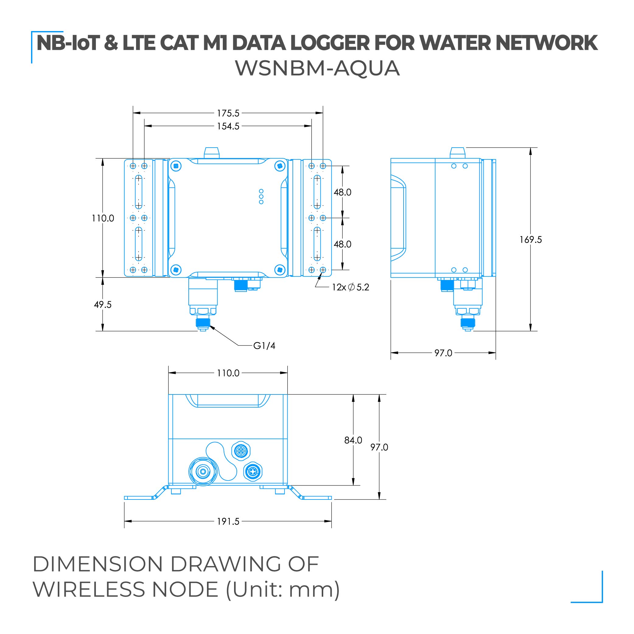
1.8.1 Installation drawings
Dimension drawings for installation as below
1.8.2 Check list for installation
Please follow the checklist below for a successful installation:
1. Have you studied the dimensions of the device as above drawings?
2. Have you tested and make sure the device have been connected successfully as Section "1.4 Guide for Quick Test" above?
3. Have the device been configured properly?
4. Have the device been calibrated or validated?
5. Then you can start to install the device at site. Please check the following Installation Notes for Sensor Part (if available) before installation.
1.8.3 Selection for installation location
- Make sure the site is good enough for CAT-M1/NB IoT signals.
- Choose a location far from light, heat, and vibration.
- DO NOT install the logger or its antenna inside a completed metallic box or housing because the cellular signal can not pass through the metallic wall. The housing is made from Non-metallic materials like plastic, glass, wood, leather, concrete, and cement…is acceptable.
1.8.4 Sample installation

1.9 Payload Document and Configuration Tables
Pease click below link for:
- Payload decoding of Uplink messages;
- Payload encoding of Downlink messages;
- Configuration Tables of device.
Click Payload document and configuration table to download Payload Document and Configuration Tables
1.10 How to connect device to MQTT Broker
Please find below the examples of adding Daviteq's MQTT device to the following MQTT broker:
- Mosquitto MQTT broker
No Comments