3. Advanced guide for WSNBM-AQUA
3.1 Principle of Operation
Daviteq WSNBM-AQUA comprises 04 parts linked internally:
• Pressure Sensor
• RS485 ModbusRTU Master
• Device controller
• CAT-M1/NB IoT modem
3.1.2. The parameters in published topic name
- SKU: Device SKU, read from DEVICE_SKU parameter in the device memory, max 20 characters, data type of string.
- DEVICE NAME: Device name, read from DEVICE_NAME parameter in device memory, max 20 characters, data type of string.
- DEVICE SN: Device serial number, read from DEVICE_SN parameter in device memory, 20 characters, data type of string.
- DEVICE ALIAS: Device alias, read from DEVICE_ALIAS parameter in device memory, max 20 characters, data type of string.
- TOPIC TYPE: Fixed type of the topic. One of below topic type:
-STARTUP
-HEARBEAT
-CONFIG-HEALTH-CHECK
-FORCE
-CYCLE
-CONFIG-RECEIPT
-CONFIG-REQUEST
3.1.3. Primary output values in the payload of published topics
3.1.4. Secondary output values in the payload of published topics
3.1.5. The parameters in subscribed topic name
- SKU: Device SKU, read from DEVICE_SKU parameter in the device memory, max 20 characters, data type of string.
- DEVICE NAME: Device name, read from DEVICE_NAME parameter in device memory, max 20 characters, data type of string.
- DEVICE SN: Device serial number, read from DEVICE_SN parameter in device memory, 20 characters, data type of string.
- DEVICE ALIAS: Device alias, read from DEVICE_ALIAS parameter in device memory, max 20 characters, data type of string.
- TOPIC TYPE: Fixed type of the topic. The topic type is CONFIG-REQUEST, a request to change the parameter.
3.1.6. Parameters in the payload of subscribed topic name
Subscibed Topic Type: Fixed type of the topic is CONFIG-REQUEST. This parameter is topicType in the published topic's payload.
Epoch Time: Topic's Epoch Time format, unit of millisecond. This parameter is epochTime in the published topic's payload.
Device Serial Number: Device serial number. This parameter is deviceSerialNumber in the published topic's payload.
Start Address: Start address of the changed configuration, in decimal. This parameter is startAddress in the published topic's payload.
Register Length: Register number of changed configuration, in decimal, max length = 400 hexadecimal value. This parameter is registerLength in the published topic's payload.
Requested Value: Requested value for the configuration change, in hexadecimal. This parameter is requestedValue in the published topic's payload.
3.1.7. Device operation flow chart
3.1.8. Device operation principle description
When a device subscribes to the CONFIG-REQUEST topic successfully, device implements the configuration change request and publishes CONFIG-RECEIPT topic to acknowledge the receipt of the CONFIG-REQUEST topic.
3.2 Configuration
3.2.1. How to configure the device?
Sensor configuration can be configured in 02 methods:
Method 1: Online configuring via Subscribing CONFIG-REQUEST topic from MQTT Application.
Method 2: Offline configuring via Offline cable.
3.2.2 Which Parameters are configured?
Please check Part E. MEMORY MAP in Section 1.9 Payload Documents above.
3.2.3 Online configuring via subscribing CONFIG-REQUEST topic from MQTT Application.
Please refer Part C. SUBSCRIBE TOPIC in Section 1.9 Payload Documents above.
3.2.4 Offline configuring via Offline cable.
Please download the Configuration Template File of this sensor to be used in Step 4 below.
Click Download CSV file to download the Configuration Template File
Instructions for offline configuration of the Seismic sensors. Please follow the following steps.
Prepare equipment and tools
The following items must be prepared for configuration.
- A PC using the Windows OS (Windows 7 or above versions). The PC installed the COM port driver of the Modbus configuration cable (if needed). The driver is at link: Modbus Configuration Cable COM port driver for PC and the instruction to install the driver at link: How to install the driver.
- A Modbus configuration cable
- A M12-CAB-CONFIG cable
Download and launch Modbus configuration software
-
Click the link below to download Modbus configuration software:
Click Modbus configuration software to download the software
After downloading the software, unzip the file named Modbus Configuration.zip and then copy the extracted folder to the storage drive for long-term use.
-
Open the folder, double click on the file Modbus Configuration Tool Version.exe to launch the software and the software interface as below:
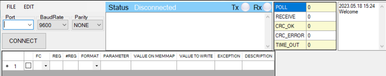
Note: The software only runs on Microsoft Windows OS (Windows 7 and above)
Connect the cable and configure the sensor
Step 1:
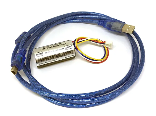
Connect the PC to the Battery Pack using the configuration cable and converter cable
- Use the configuration cable (Item code: TTL-LRW-USB-01).
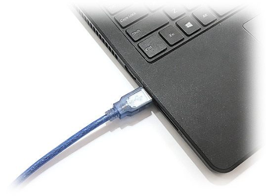
- Connect the USB-A plug into the USB-A socket of the PC.
Step 2:
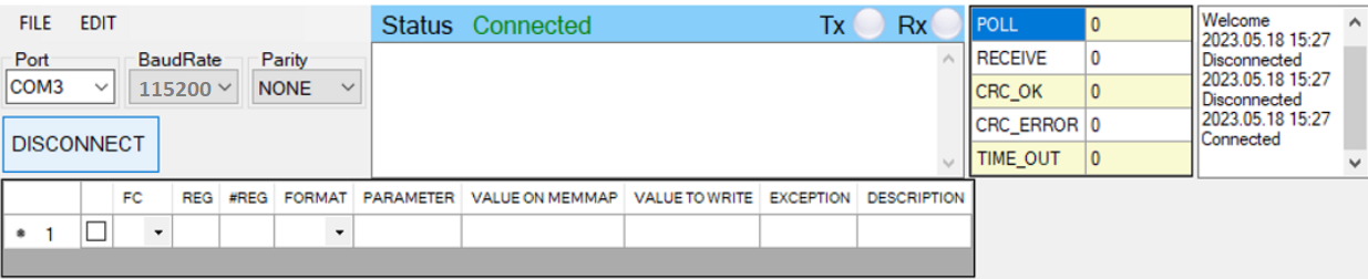
On the configuration software, choose the relevant Port (the USB port which is the cable plugged in) and set the BaudRate: 115200, Parity: none
Step 3:
Step 4:
Import the configuration template file of the sensor (as above link) to the software: click menu File/ Import New and then browse the relevant sensor template file (csv file) and click Open to import the template file.
Each sensor type has its own template file. Refer to the sensor's manual to download the correct file.
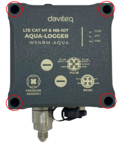
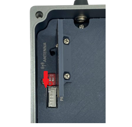
Step 5: Open the housing of the sensor and quickly plug the connector of the configuration cable into sensor's modbus configuration port. After that, turn on the switch 1. After the switch 1 is on, the software will read the parameter values automatically.
|
- Open the housing of the sensor. |
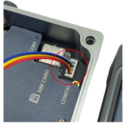 - Plug the cable connector into sensor's Modbus configuration port.Note: this port is located at a different location, depends on the sensor type |
- Turn on the switch 1 |

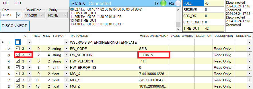
Step 6: Read the current value of the parameter with function 3
- At the relevant row of the parameter, check box 3 on column FC to read the value of the parameter. The read value is shown on VALUE ON MEMMAP column.
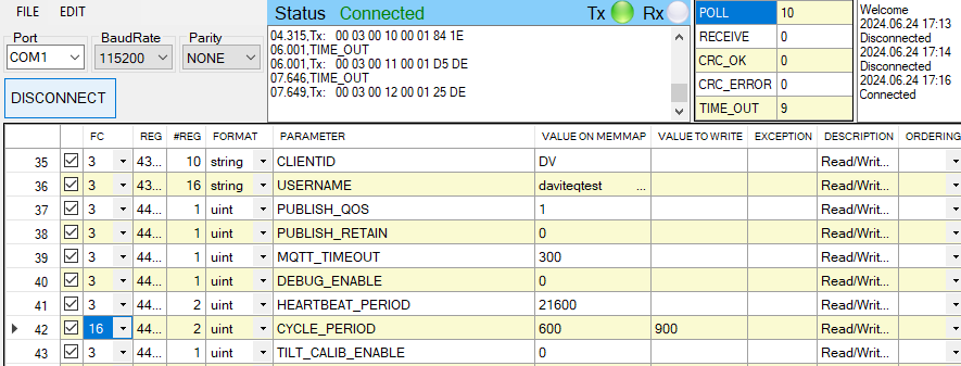
Step 7: Write the new setting to the parameter with function 16
- Double click on the column VALUE TO WRITE of the parameter and input the new setting of the parameter
- Uncheck the tick on the FC column of the parameter, click on the arrow, select 16 and then check on the FC column to write a new setting to the parameter. The WRITE_OK text will show on EXCEPTION column if the software successfully writes the setting.
- Repeat step 6 to read the setting of the parameter for checking.
Step 8: Turn off switch 1 (configuration switch) of aqua logger
For some critical parameters of the sensor, the password in "password for setting" must be written before writing the new settings to these parameters.
Only read/write registers are allowed to write.
After completing configuration, if the switch 1 (configuration switch) is NOT switched off, the battery life will be shorten.
Troubleshooting of offline configuration
| No. | Phenomena | Reason | Solution |
|---|---|---|---|
| 1 | The status on the software always shows Disconnected although the configuration cable is connected to the PC | The selected COM port is incorrect | Select the correct COM port to which the configuration cable connects to PC |
| The configuration cable is defective | Check the configuration cable | ||
| 2 | The software reads no value after importing the right template and connecting the right cable. | The cable is defective or lost connection | Check or replace the new configuration cable |
| The USB port is defective | Check USB port | ||
| There is no power supply to the sensor via configuration cable | Check the power line of the cable | ||
| The sensor or sensor port is defective | Check the sensor and sensor port | ||
| 3 | No COM port appears in the Port list | No configuration cable is plugged into the PC | Plug the cable to the PC |
| The cable driver is not installed on the PC | Install the driver for the PC | ||
| 4 | The parameter table on the software is empty | The template file has not been imported | Click menu File and sub-menu Import New to import the template file |
| 5 | The parameter table on the software does NOT match the memory map table of the sensor. | The wrong template file was imported. | Go to the correct manual page of the product and download the right template file, then import the template file into the software. |
3.3. Update CA file to WSNBM-AQUA
3.3.1. Upload the CA file to a download server
The CA file must be uploaded to a server that supports direct download functionality.
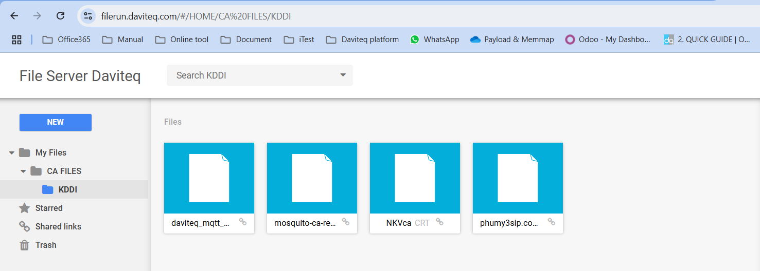
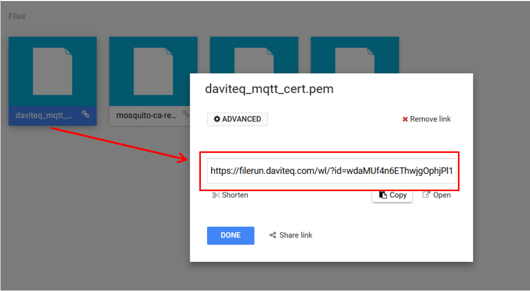
Get the CA file link after uploading successfully
3.3.2. Connect the PC to Aqua logger via configuration cable
Refer to section 3.2.4 Offline configuring via Offline cable for instructions on configuring the Aqua logger
Download the template file for uploading CA file from the link
- After connecting the configuration cable from PC to Aqua logger, open the configuration software and import the template file for uploading the CA file
- Wait until the logger is connected to the internet (Indicated by EPOCH_TIME = REAL TIME)
Online tool for converting Epoch time to real time in the link
3.3.3. Configure the logger to automatically download the CA file from server
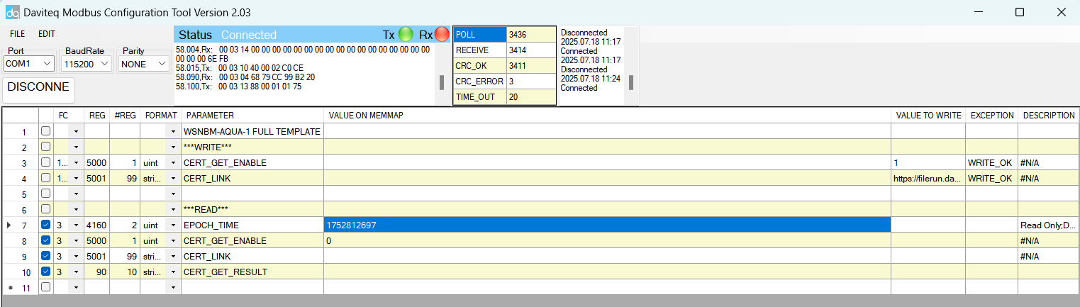
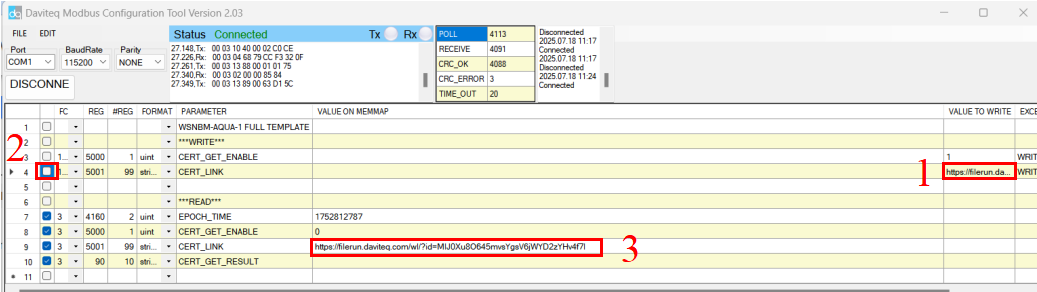
- Input the download link of CA file (in section 3.3.1) into the cell in VALUE TO WRITE column corresponding to CERT_LINK(1)
- Tick the cell corresponding to CERT_LINK as in the picture below (2) to write the link to the logger.
- Wait a few seconds, then check the value in the cell (3). Ensure the cell display the correct download link of the CA file.
3.3.4. Verify that the CA File has been uploaded successfully.
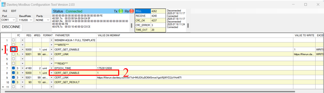
- Tick the cell corresponding to CERT_GET_ENABLE (1) to enable the logger download new CA file
- Wait a few seconds, then check the value in the cell (2), ensure the cell display the value 1
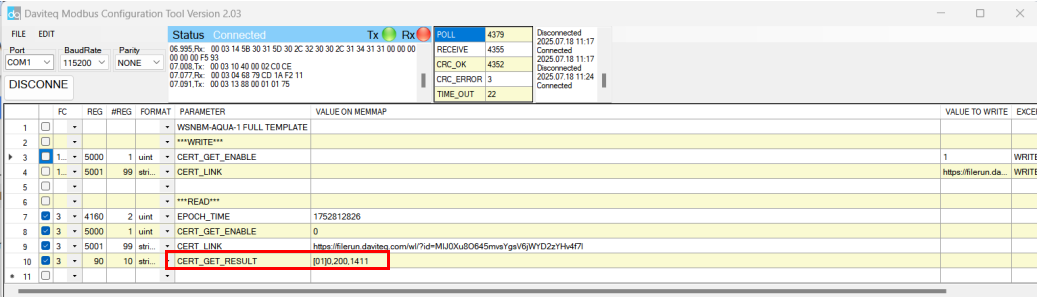
- Continue waiting for a minute, then check the value in the cell corresponding to CERT_GET_RESULT. If the cell displays the value in the same format as shown in the picture below, the CA file was uploaded successful.
In the picture, 1411 is the length of the CA file. Each CA file will have its own value.
No Comments