USER GUIDE FOR LONG RANGE WIRELESS CO-ORDINATOR WS433-CL AND WIRELESS RADAR LEVEL METER
| WS433-CL-MN-EN-01 |
JUN-2021 |
This document is applied for the following products
|
SKU |
WS433-MA |
HW Ver. |
2.5 |
FW Ver. |
5.0 |
|
Item Code
|
WS433-MA-31 | Wireless Sensor 1-channel 0-20mA DC current input, IP67, battery AA 1.5VDC, 24VDC Output for Instrument power supply | |||
|
SKU |
RD269X |
HW Ver. |
|
FW Ver. |
|
|
Item Code |
RD2695S-P-B(J)-04-A3(04)-V-4-L-N-V-6 | 26GHz RadarLevel transmitter, 78mm PVDF protection tube, SUS304 JIS10K 80A RF Flange, 0-6m cablibrated range, 4-20mA output, looped power, HART, IP67 aluminum housing | |||
| SKU | STHC-ISGETH | HW Ver. | 1.0 | FW Ver. | e1.4 |
| Item Code |
WS433-CL-04 | Wireless Sensor Co-ordinator with external antenna 0 dbi, M12-Female connector, 4-pin, coding A, RS485 ModbusRTU | |||
| RS485-FM12-USB-1 | RS485/USB multi-purpose Configuration cable** with connector m12 male, female and flying leads, with Power adapter 12VDC/2.0A | ||||
1. Functions Change Log
| HW Ver. | FW Ver. | Release Date | Functions Change |
| 2.4 |
1.9
|
NOV-2019 |
|
2. Specification
2.1 WS433-MA Specification
| Measuring range | 0 .. 20mA |
| Accuracy | 0.05% of span |
| Resolution | 1/3000 |
| Temperature drift | < 50ppm |
| Optional accessories | 304SS Adapter PG9/male 1/2"NPT or PG13.5 or M20 to allow direct mounting on Process instruments or electrical panel |
| Data speed | Up to 50kbps |
| Transmission distance, LOS | 500m |
| Antenna | Internal Antenna, 3 dbi |
| Battery | 01 x AA 1.5VDC, up to 10-year operation, depends on configuration |
| Frequency Band | ISM 433Mhz, Sub-GHz technology from Texas Instrument, USA |
| Receiving Sensitivity | -110dBm at 50kbps |
| International Compliance | ETSI EN 300 220, EN 303 204 (Europe) FCC CFR47 Part15 (US), ARIB STD-T108 (Japan) |
| Security Standard | AES-128 |
| Operating temperature of PCB | -40oC..+60oC (with AA L91 Energizer) |
| Housing | Poly-carbonate, IP67 |
| Installation method | L-type bracket SUS304 , by M4 screws or double-sided 3M tape (included) |
| Product dimensions | 125x30x30mm |
| Net weight (without battery) | < 100g |
| Box dimension | 190x50x50mm |
| Gross weight | 140g |
2.2 RD-2695S Specification
| Features | Sealed antenna with anti-corrosion cover |
| Application | Be suitable for strong acids, alkalis, or other strongly corrosive liquids, or liquids with heavy steam, etc. |
| Antenna size | ** 62mm, corresponding to flange sizes, DN80, DN100 ** 96mm, corresponding to flange sizes, DN150, DN200 |
| Measuring range (Maximum) | 35m |
| Process connection | Flange |
| Process temperature | -60°C … +150°C |
| Process pressure | -0.1 ~ 1.0MPa |
| Accuracy | ±3mm |
| Frequency range | 26GHz |
| Explosion proof | Ex ia IIC T6 |
| Enclosure protection grade | IP67 |
| Signal output | 4-20mA/ HART (2-wire/ 4-wire), RS485/ Modbus |
3. Operation Principle
3.1 Sensor configuration
IN CASE the sensor need to be added to WS433-CL-04 (1) has been installed in a high position, the sensor cannot be brought close to WS433-CL-04 (1).
First, you need to prepare

For example: WS433-CL-04 has connected 1 sensor node and needs read value sensor. So we use a WS433-CL-04 to configure the sensor connected to WS433-CL-04
Step 1: Add Sensor Node ID automatically to WS433-CL-04
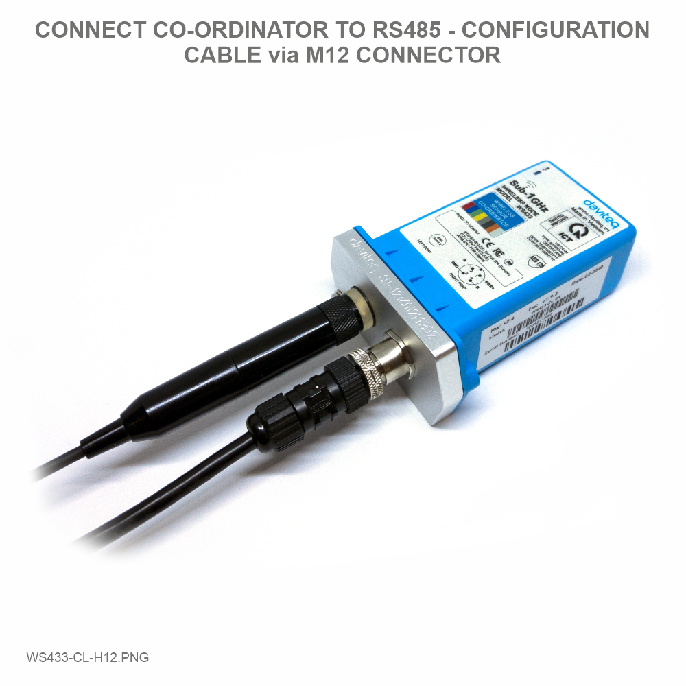
Step 2: Use the RS485 configuration cable to communicate with the Co-ordinator WS433-CL-04 via Modbus software (in the link below)
Daviteq Modbus Configuration Tool: https://filerun.daviteq.com/wl/?id=qK0PGNbY1g1fuxTqbFW9SXtEvCw7bpc6
Template RADAR sensor configuration: https://filerun.daviteq.com/wl/?id=1ZNVkHMxCTj0fxWZXrwtWbrr2MYfSc3S
How to use the Modbus configuration software
 |
 |
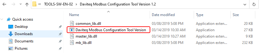
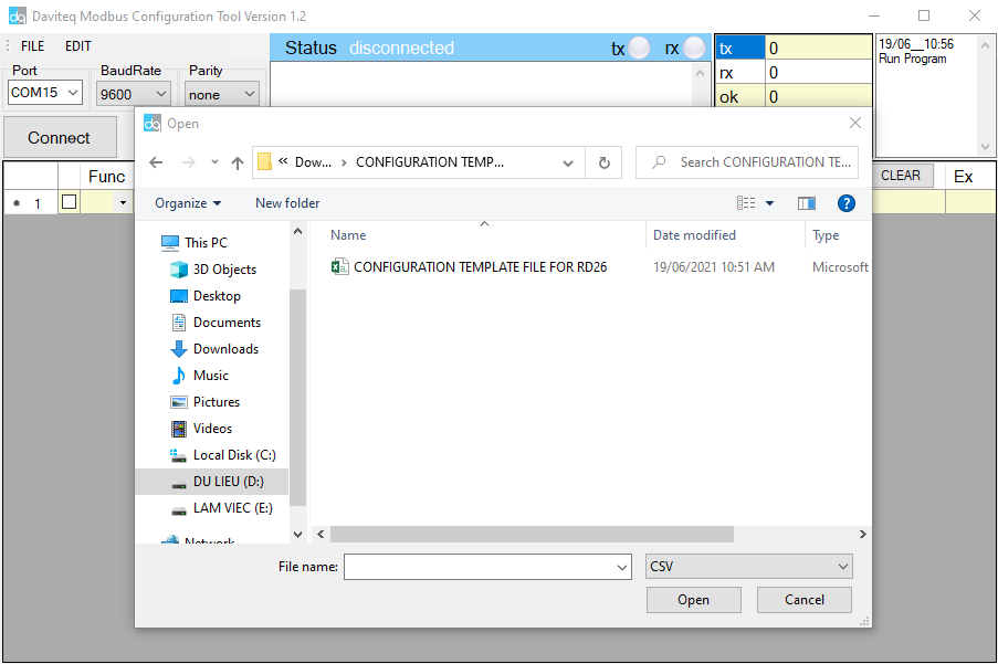
- Unzip file and run file application Daviteq Modbus Configuration Tool Version
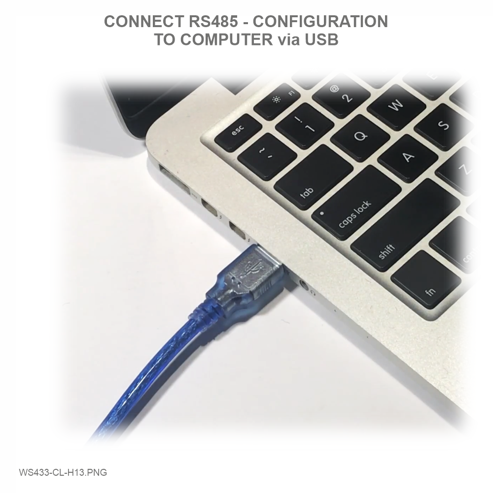
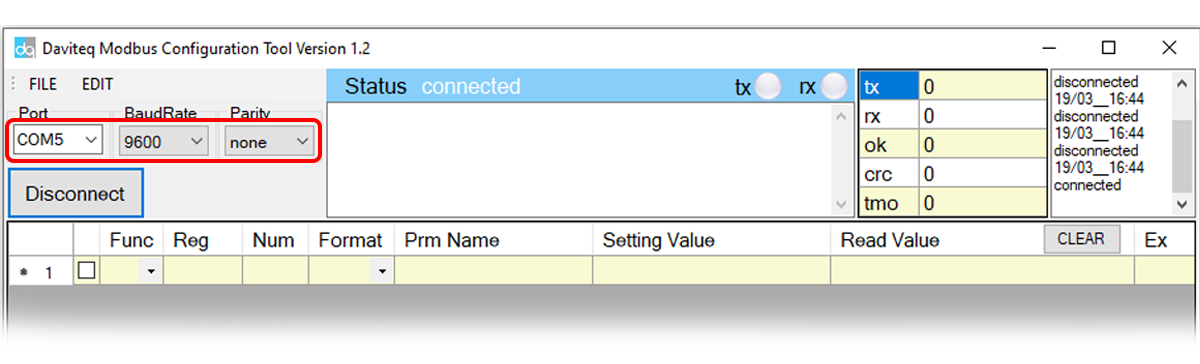
- Choose COM Port (the Port which is USB cable plugged in)
- Set the BaudRate: 9600, Parity: none

- Click “ Connect “ untill the Status displays “disconnected” to “connected“. It means the WS433-CL-04 is being connected with computer;
- Next, we need to import the configuration file for WS433-CL-04 by importing the csv file: Go to MENU: FILE / Import New / => select the file with name CONFIGURATION TEMPLATE FILE FOR RD26.csv (after unzip file).
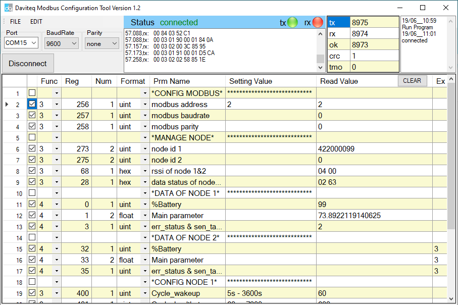
- We can see that WS433-CL-04 has connected the sensor to the sensor's id node s/n with the sensor
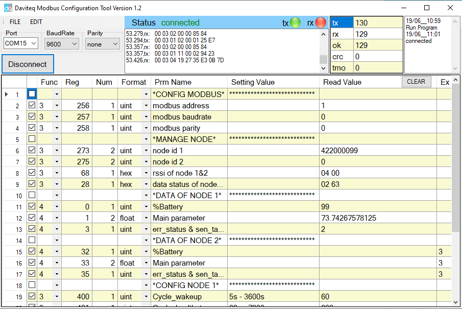
- In the row modbus address , we change the ID address of WS433-CL-04 by Uncheck Func 3 => change Func from 3 to 16

- Type in Setting Value the modbus address of WS433-CL-04 => Check Func 16 if Read Value show OK which mean it's wrote successful


- Change Func 16 to 3 then Check to read the value we just wrote in => if Read Value show the co-ordinator id of WS433-CL-04 that mean the sensor node has sync with WS433-CL-04
- Function 3: Read holding registers
- Function 4: Read input registers
- Function 16: Preset Multiple registers
3.2 Data packet :
| Parameter name | Description |
| modbus address | ID address of WS433-CL |
| modbus baudrate | Default (9600) |
| modbus parity | Default (None) |
| node id 01 | Serial number of sensor 01 |
| node id 02 | Serial number of sensor 02 |
| rssi of node 1&2 | Hi-byte : RF signal sensor 01 Lo-byte : RF signal sensor 02 |
| data status of node 1&2 | Hi-Byte : data status of node 1 Lo-Byte : data status of node 2 |
| %Battery | High byte "spare", low byte is % battery capacity. Battery capacity has 4 levels: 10%, 30%, 60%, 99%. |
| main parameter | The measured value of the main parameter. Depending on the type of sensor, the measurement value is temperature, humidity, pressure difference, pressure, AC current measurement, digital input, mA, volt, relay,... Depending on the measurement parameters, the data type will be different, described specifically in the documentation of that sensor. |
| err_status & sen_tatus | High byte indicates "ERROR". Byte low indicates "Type SENSOR". |
3.3 Status bytes of sensor Node
-
Hi-Byte is error code
|
Error code |
Description |
|
0 |
No error |
|
1 |
Just exchange the sensor module but node has not been reset ==> please take out the battery for 20s then install it again to reset node to recognize the new sensor module |
|
2 |
Error, sensor port M12F shorted to GND |
|
3 |
Error, sensor port M12F shorted to Vcc |
|
4 |
Error, sensor port M12F shorted each other |
|
51 |
Check sum error of sensor port |
- Lo-Byte is sensor type
|
Sensor type |
Description |
|
1 |
Ambient temperature sensor |
|
2 |
Ambient humidity sensor |
|
3 |
Ambient differential pressure sensor |
|
4 |
Process pressure sensor |
|
5 |
1-channel AC 5A current sensor |
|
6 |
2-channel digital input with counters |
|
7 |
2-channel digital input with status detecting |
|
8 |
Ambient light sensor |
|
9 |
1-channel 0-20mA analog input |
|
10 |
Relay output 2 SPDT or 4 SPST |
|
11 |
Soil moisture sensor with I2C |
|
12 |
Soil moisture sensor with RS485 |
|
255 |
No sensor |
- RF signal strength of node is the row rssi of node 1&2
- Hi-Byte is rssi of node 1
- Lo-Byte is rssi of node 2
|
RF signal strength |
|
|
0 |
RSSI < -100dBm |
|
1 |
RSSI = -80…-100dBm |
|
2 |
RSSI = -70…-79dBm |
|
3 |
RSSI = -55...-69dBm |
|
4 |
RSSI = 0…-54dBm |
- Data status of node is the row data status of node 1&2
- Hi-Byte is data status of node 1
- Lo-Byte is data status of node 2
|
Data status |
|
|
99 |
Have not received data from wireless sensor |
|
0 |
when data from wireless sensor just arrived in within "cmp time 1" seconds |
|
1 |
when data from wireless sensor just arrived in within "cmp time 2" seconds |
|
2 |
when data from wireless sensor just arrived in within "cmp time 3" seconds |
|
3 |
when data from wireless sensor just arrived in within "cmp time 4" seconds |
|
4 |
when data from wireless sensor just arrived in within "cmp time 5" seconds |
|
5 |
when data from wireless sensor just arrived in within "cmp time 6" seconds |
|
6 |
when data from wireless sensor just arrived in within "cmp time 7" seconds |
|
7 |
when data from wireless sensor just arrived in within "cmp time 8" seconds |
|
8 |
when data from wireless sensor just arrived in within "cmp time 9" seconds |
|
9 |
when data from wireless sensor had arrived longer than "cmp time 9" seconds |
3.4 Synchronizing configuration between WS433-CL and node:
|
# of register |
Description |
Value Range |
Default |
Format |
Explanation |
|
1 |
Cycle_wakeup |
1-3600(s) |
120 |
uint16 |
Every time interval of Cycle_wakeup, sensor node would ONLY send data to co-ordinator if the new measured value was changed more than the Delta value of the last measured value. Default Cycle_wakeup is 120 seconds |
|
1 |
Cycle_healthsta |
60-7200(s) |
600 |
uint16 |
Every time interval of Cycle_healthsta, sensor node will absolutely send data to co-ordinator regardless any condition |
|
2 |
a1 |
1 |
float |
Scale value of parameter_1 = (a1 * Raw sensor value of parameter_1) + b1. For sensor value scale |
|
|
2 |
b1 |
0 |
float |
Scale value of parameter_1 = (a1 * Raw sensor value of parameter_1) + b1. For sensor value scale |
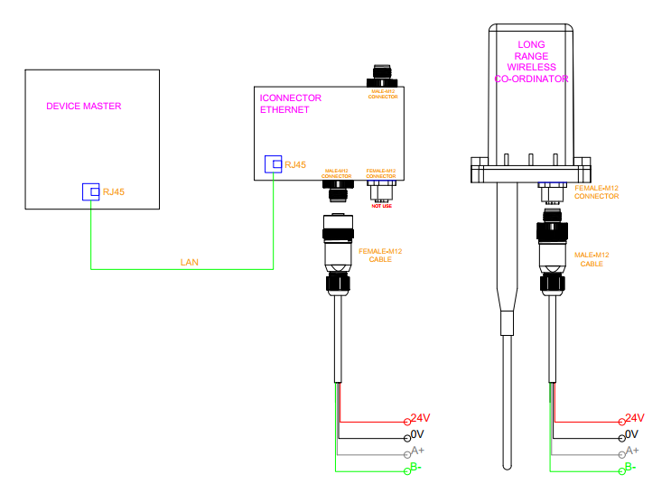
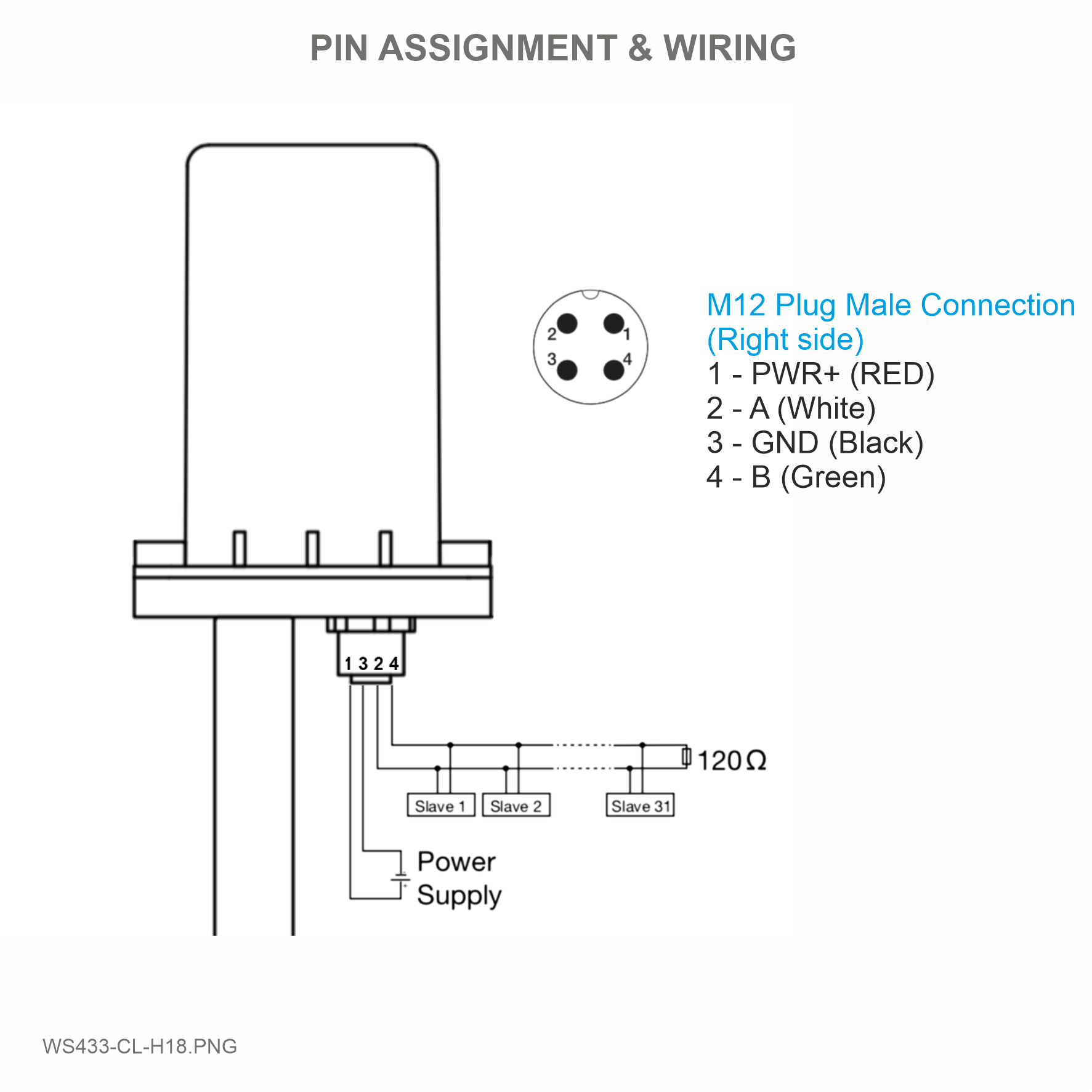
3.5 Wiring
4. iConnector Ethernet
4.1 What is TCP/IP ?
4.2 Configure with iConnector Config software
Refer to section 5 for more details on how to use Configuration Cable
4.2.1 Ethernet tab
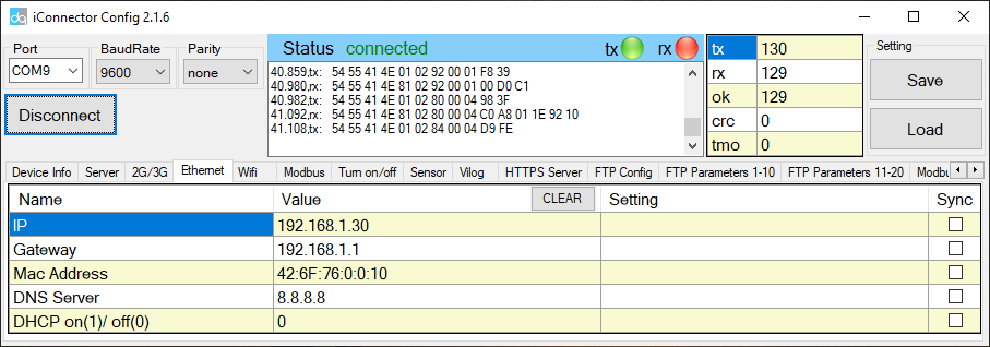
| Name | Description |
| IP | Static IP configuration for iConnector. Example: 192.168.1.30 |
| Gateway | Configure gateway |
| DNS Server | Configure DNS Server |
| DHCP |
0 (Off) / 1 (On) If DHCP = 0, it's mean Not using DHCP → Static IP |
4.2.2 Modbus-TCP-Server tab
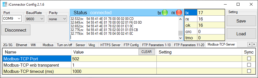
| Name | Description |
| Modbus-TCP Port | Configure the receiving port, for example 502 |
| Modbus-TCP enb transparent |
1 : To run transparent, interrupt modbus RTU poll. 0 : Run modbus RTU poll as normal iConnector, not transparent |
| Modbus-TCP timeout (ms) | Used for modbus TCP Server |
4.3 Description of transparent mode operation (Modbus-TCP enb transparent = 1)
Suppose we have: Static IP address: 192.168.1.30 | Port 502
1. iConnector is connected to the Modbus RTU with electric meters, devices, ... via RS485 port;
2. Software / device / PLC ... with Modbus TCP Client connected to iConnector (role as TCP Server) at Static IP address 192.168.1.30 | Port 502 in internal network;
3. TCP Client sends command to iConnector;
4. iConnector transfers commands from Modbus TCP to RTU and sends to devices and clocks via RS485 port;
5. iConnector waits for the devices to respond;
6. iConnector transfers the response from the RTU to the Modbus TCP and then sends it back to the TCP Client;
7. TCP Client actively closes the connection if it no longer sends command to iConnector.
4.4 Run Modbus RTU as normal iConnector (Modbus-TCP enb transparent = 0)
4.4.1 TCP Client connects to iConnector via internet
1. iConnector needs static IP configuration, For example: IP 192.168.1.30 | Port 502
2. The external internet network must also have a static IP, Example: IP 118.69.111.101
3. Network administrator must implement NAT port 502, TCP to IP of iConnector
4. At that time, TCP Client will connect to IP address 118.69.111.101 | Port 502
4.4.2 TCP Client read/write parameters on the iConnector memmap
iConnector supports command 3 (0x03) for read, command 16 (0x10) for writing.
The Unit Identifier is 31 (0x1F) to read and write memmap iConnector, not 31 will make devices transparent read and write via RS485.
These commands are changed to match the address of iConnector (address in bytes but not in registers like modbus).
1. Command 3:
Modbus TCP is:
0001 0000 0006 1F 03 006B 0003
- 0001: Transaction Identifier
- 0000: Protocol Identifier
- 0006: Message Length (6 bytes to follow)
- 1F: The Unit Identifier (31 = 1F hex)
- 03: The Function Code (read Analog Output Holding Registers)
- 2000: The Data Address of the first register requested → This will be the address on the memmap
- 0003: The total number of registers requested. (read 3 registers 40108 to 40110) →This number 3 will be 3 bytes, not 3 registers anymore.
At that time iConnector will respond to data of 3 bytes, not 6 bytes
2. Command 16:
Modbus TCP is:
0002 0000 0009 1F 10 3000 0002 04 000A
- 0002: : Transaction Identifier
- 0000: Protocol Identifier
- 0009: Message Length (6 bytes to follow)
- 1F: The Unit Identifier (31 = 1F hex)
- 10: The Function Code 16 (Write Function)
- 3000: The Data Address of the first register requested → This will be the address on the memmap
- 0002: The number of registers to write → This is the length to write is 2 bytes, not 2 more registers.
- 04: The number of data bytes to follow
- 000A: The value to write to register → data 2 bytes need to write
4.4.3 Recommend modbus TCP/IP registers for RADAR sensor
| Parameter Name | Address | Data Type | Data Length | Sensor |
| Battery 01 | 6000 | unsigned_integer_16 | 2 | 01 |
| 1st - Parameter 01 | 6002 | float | 4 | 01 |
| ERROR 01 | 6006 | byte | 1 | 01 |
| Type SENSOR 01 | 6007 | byte | 1 | 01 |
| Battery 02 | 6041 | unsigned_integer_16 | 2 | 02 |
| 1st - Parameter 02 | 6043 | float | 4 | 02 |
| ERROR 02 | 6047 | byte | 1 | 02 |
| Type SENSOR 02 | 6048 | byte | 1 | 02 |
5. Installation
5.1 Mounting bracket installation
The mounting bracket is made from hard metallic material. Following to these steps as the below picture
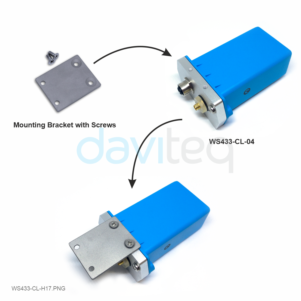
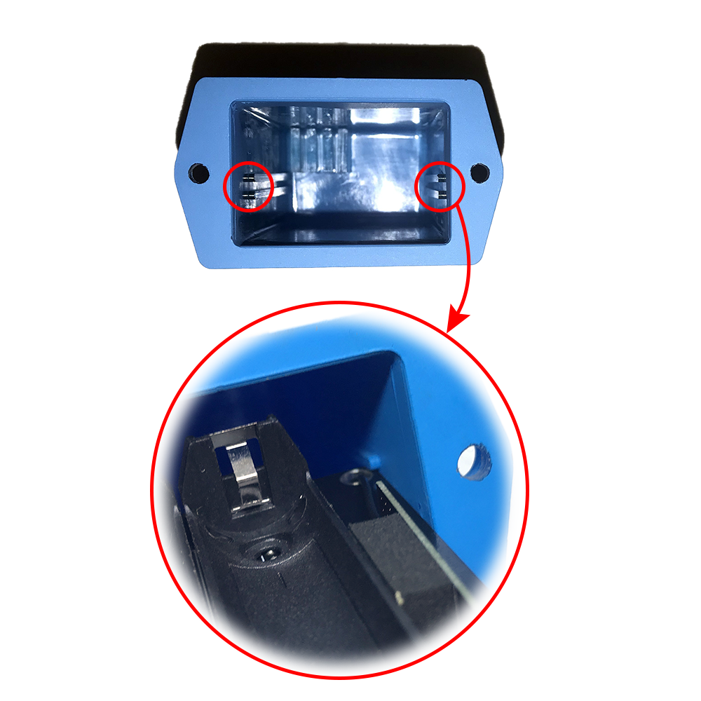
Insert the top plastic housing and locking by L hex key
(NOTE: When reinstalling the cover, pay attention to put the PCB edge into the middle slot of the box inside as shown below)
5.2 Installation location
To maximize the distance of transmission, the ideal condition is Line-of-sight (LOS) between the two modules. In real life, there is no LOS condition. However, the two modules still communicate each other, but the distance will be reduced significantly.
Therefore, to maximize the transmission distance, please pay attention to the following conditions:
- DO NOT install the wireless module inside a complete metallic box or housing. The signal can not pass through metallic wall;
- This wireless module would be installed a semi-metallic box, because the RF signal can pass through the non-metal wall/are;
- The best case is to install the wireless module inside or Non-metallic box;
Some non-metallic materials: plastic, glass, wood, leather, concrete, cement…
5.3 IO Wiring & Sensor installation
 |
 |
 |
 |
6. Troubleshooting
| No. | Phenomena | Reason | Solutions |
| 1 | Cannot read modbus |
|
|
| 2 | Failed to add auto sensor |
|
|
| 3 | Read modbus normal health values but read the data of the node, all are 0 |
|
|
| 4 | The node's data has no data of prm1 and prm2 |
|
|
7. Support contacts
|
Manufacturer
Daviteq Technologies Inc Email: info@daviteq.com | www.daviteq.com
|
Distributor in Australia and New Zealand
Templogger Pty Ltd Tel: 1800 LOGGER Email: contact@templogger.net |

No Comments