USER GUIDE FOR SMART VORTEX FLOW METER SVF128
| SVF128-MN-EN-01 |
MAY-2021 |
This document is applied for the following products
| SKU | SVF128 |
1. Functions Change Log
| HW Ver.
|
FW Ver. |
Release Date |
Function Change |
|
1.0 |
1.0 |
MAY-2021 |
2. Introduction
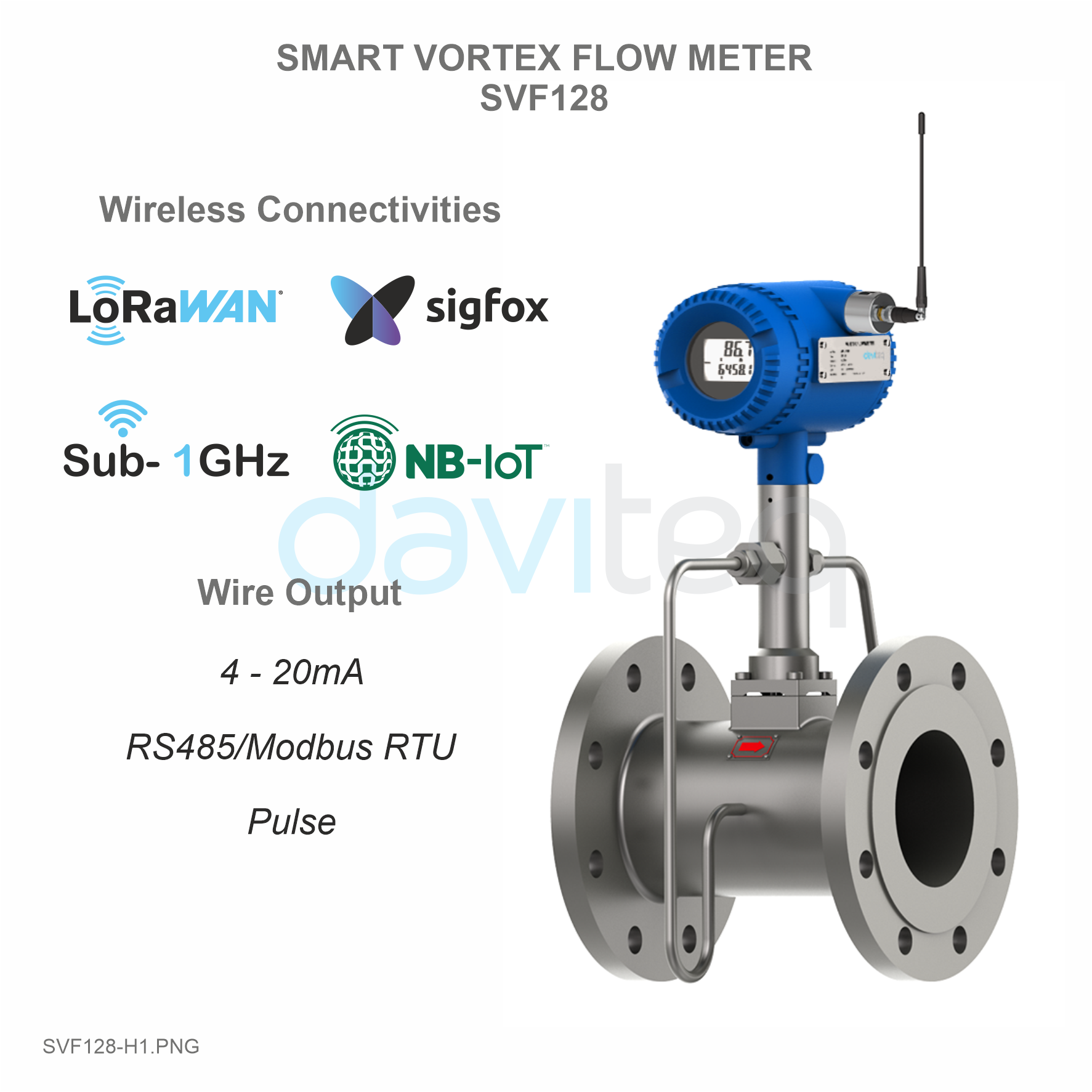
SVF128 Vortex flow meter is a smart vortex flow meter utilizing “Karman vortex” theory to measure the velocity of fluid then calculate the flow rate in volume or mass. VFM128 is to use for various fluids such as gas, steam and liquid. The flow meter come with local or remote display and different type output such as 4-20mA, pulse, RS485 ModbusRTU, Hart for easily integrate into any PLC, SCADA, DCS system. The flow meter can be upgraded with latest wireless connectivity such as Sub-GHz, LoRaWAN, Sigfox, NB-IoT, 3G/4G... allow it to connect to any IoT platform such as Globiots, Azure, AWS...
Typical Applications: Saturated Steam, Super-heated Steam, Compressed Air, Liquid, Industrial Gases: Nitrogen, Oxygen... or Fuel Gas: Natural Gas...
3. Specification
| Process Fluids | Liquid, Gas, Steam, Compressed Air |
| Process connection | Flange or Wafer for size DN15~DN300 or 0.5 inch to 12 inch |
| Local Display | Standard integral LCD display. Optional Remote display with 10m cable |
| Measurable Parameters of standard version | Volumetric flow rates and totalizer, velocity. |
| Measurable Parameters of Multi-variables version | Mass flow rate, volumetric flow rate, temperature, pressure, velocity. |
| Output | Pulse, 4~20mA (HART V5, V7 @4~20mA), ModBus-RTU RS485 |
| Process Pressure | 1.6MPa (232 psiG),2.5MPa (362 psiG),4.0MPa (580 psiG),6.3Mpa (913 psiG) for option |
| Process Temperature | Standard type: -40 ~ 150 °C or -40 ~ 302 °F Medium type: -40 ~ 250 °C or -40 ~ 482 °F High temperature type: -40 ~ 350 °C or -40 ~ 662 °F |
| Gas flow Turndown | DN15, DN20: Turndown ratio 10:1 DN25, DN32: Turndown ratio 15:1 DN40~DN300: Turndown ratio 30:1 |
| Steam flow Turndown | DN15, DN20: Turndown ratio 11.6:1 DN25, DN32: Turndown ratio 17.5:1 DN40~DN300: Turndown ratio 35:1 |
| Liquid flow Turndown | 23:1 |
| Accuracy | Gas/Steam: ±1%RD(Re ≥ 20000), ±2%RD(10000 ‹ Re ‹ 20000) Liquid: ±0.75%RD(Re ≥ 20000), ±2%RD(10000 ‹ Re ‹ 20000) |
| Repeatability | ±0.3% of flow reading, ±0.05 °C for temperature, ±0.05%FS of pressure |
| Upstream/Downstream required | 15D / 5D |
| Viscosity allowance | DN15 or 0.5 inch ≤ 4mPas DN25 or 1 inch ≤ 5mPas DN40~DN300 or 1.5~12 inch ≤ 7mPas |
| Anti-vibration (both punch and fixed freq) | 0.5g |
| Power Supply | 15.5 .. 42 VDC |
4. Measuring principle
Vortex flowmeter measures the flow by sensing the vortices in the flow according to “Karman Vortex Street”. When put an shedder in the path of flow, vortices are alternately shed on each side (see picture 4.1)
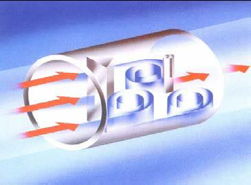
Picture 4.1: Von Karman Vortex
The frequency of vortices (f) is in direct ratio with velocity of flow (v) and in inverse ratio with width of obstacle (d).
f=St*v/d (formula 1)
v=fd/St (formula 2)
St is Strouhal Number, is a dimensionless constant related to shape of the shedder, which can be get by testing. St is Strouhal Number, is a dimensionless constant related to shape of the shedder, which can be get by test.
Because d and St is constant, flow velocity (v) and average velocity (v0) also have certain relationship ( v0=v/(1-1.25d/D) ), so, you could get v0 by having the frequency of vortices shedding (f) , and then get the mass flow. The ration between quantity of vortex in a certain period of time and the volume of the flow pass by is called coefficient of the instrument (K)
K=N/V (formula 3)
VFM60 series digital vortex flowmeter is designed to provide most reliable performance. This series of vortex flowmeter is designed on Comate Intelligent Sensor PA60 platform .Every parts utilized is universal for all VFM60 series products. The circuit boards use signal isolation and self-diagnose technology. VFM60 series utilize spectrum analyzing signal process technology, which ensured lower under measuring limit and better turndown ratio. The enhanced version use unique dual-sensor design and vibration signal analyzing technology to improve its anti-vibration capability and provide with more stable reading. VFM60 also has density calculation function as option, which means it can calculate the density and measure mass flow rate of air / saturated steam/superheated steam without secondary device. It also has AGA-NX-19 and AGA-8 algorithm to measure natural gas directly.
5. Installation
5.1 Find Most Suitable Location
(1) Ambient temperature
Please avoid installing the flowmeter at a location where temperature could dramatical changes. If the meter is under heavy heat radiation , please implement effective heat insulation and venting method.
(2) Atmosphere
Please do not install the meter at a location where the atmosphere contains a high level of corrosive substance. If can not install the meter at a better location, please make sure there is enough venting.
(3) Vibration
The meter should not be installed at a location where could have strong vibration. If the mounting pipeline could has heavy vibration, the pipe line should be hold steady by some support racks.
(4) Caution
- All screws and bolts should be tighten.
- Make sure there is not leakage point on the connection.
- The process pressure should not be higher than the meter’s rated pressure.
- Once the meter is under pressure, please do not screw the bolts and screws.
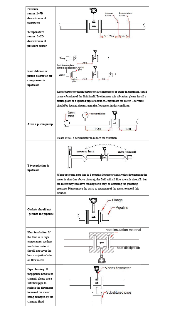
5.2 Requirement on straight pipe line
6. Wiring
VFM60 vortex flowmeter has 2 different terminal boards, the 5-terminals board and the 12 terminals board, please reference to picture 6.1 and 6.2 below.
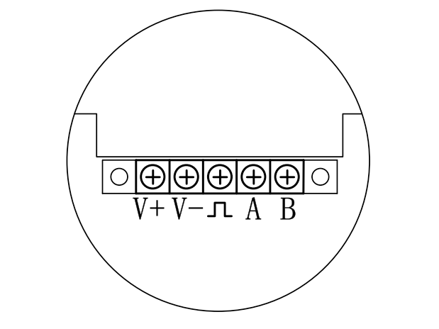
Picture 6.1: 5-terminals board

Picture 6.2: 12-terminals board
On above boards, V+ and V- are for power. ![]() is pulse output terminal. A, B are “+” and “-” for RS485Modbus communication, I+ and I- are + and – for 3-wire or 4-wire 4~20 mA.RT1, RT2, RT3 are for separate RTD. P+,P- are for pressure transmitter . VFM60 multi –variable version has built in RTD and pressure sensor, so clients are not required to wire for temperature or pressure compensation.
is pulse output terminal. A, B are “+” and “-” for RS485Modbus communication, I+ and I- are + and – for 3-wire or 4-wire 4~20 mA.RT1, RT2, RT3 are for separate RTD. P+,P- are for pressure transmitter . VFM60 multi –variable version has built in RTD and pressure sensor, so clients are not required to wire for temperature or pressure compensation.
6.1 Wiring for 5-terminal board
6.1.1 Wiring for 3 wire pulse output
3-wire pulse output require a power source of 13.5~42VDC. VFM use a current pulse output with 50% duty ratio. If the pulse receiving instrument require voltage pulse, please add a resistor between “![]() ” and “V-”, the resistance should be within 500ohms~1000ohms, and power consumption should be no less than 0.5W.
” and “V-”, the resistance should be within 500ohms~1000ohms, and power consumption should be no less than 0.5W.
Please reference to picture 6.3 picture below for 3-wire pulse output wiring.
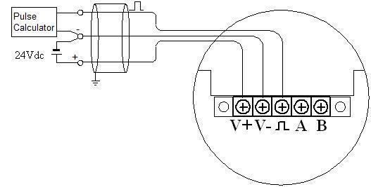
Picture 6.3: 3-wire pulse output wiring
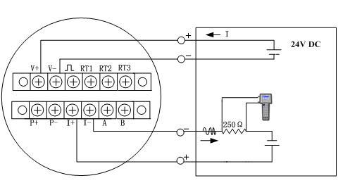
6.1.2 Wiring for 2 wire HART@4~20mA
When there is not temperate and pressure compensation and the power source is 24VDC, the max load for 4~20mA analog is 500ohms. And when there is temperate and pressure compensation and the power source is 24VDC, the max load for 4~20mA analog is 400ohms. When using a HART communicator, please add a 250ohms load resistor
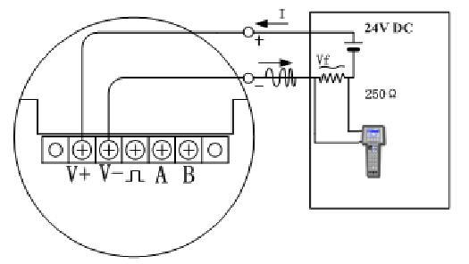
Picture 6.4: Wiring for 2 wire HART@4~20mA
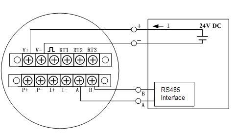
6.1.3 Wiring for RS485
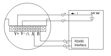
Picture 6.5: Wiring for RS485
6.2 Wiring for 12-terminal board
6.2.1 Wiring for 3 wire pulse output
3-wire pulse output require a power source of 13.5~42VDC. VFM use a current pulse output with 50% duty ratio. If the pulse receiving instrument require voltage pulse, please add a resistor between "![]() " and “V-”, the resistance should be within 500Ω ~1000Ω, and power consumption should be no less than 0.5W.
" and “V-”, the resistance should be within 500Ω ~1000Ω, and power consumption should be no less than 0.5W.

Picture 6.6: 3-wire pulse output wiring
6.2.2 Wiring for 4 wire 4~20mA
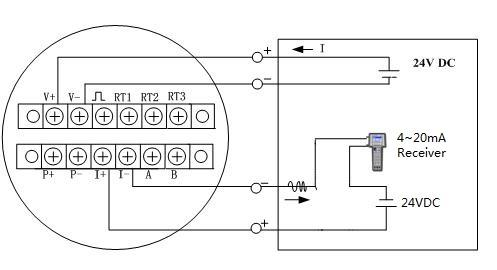
Picture 6.7: Wiring for 4-wire 4~20mA
6.2.3 Wiring for 4 wire HART@4~20mA
When power source is 24VDC, the max load for 4~20mA analog is 500Ω.
Picture 6.8: Wiring for 4-wire HART@4~20mA
Picture 6.9: Wiring for RS485
6.3 Shell grounding and elimination of interference
In VFM60 digital vortex flowmeter the power supply of signal processing circuit is transferred from outside power supply by a isolation type DC-DC transmitter with advanced grounding technology. The field frequency interference can be isolated well.
When using this product, the “V-” of power supplier should not be connected with the ground. When this product is used in a environment with strong interference , the shell should be connect with earth through cable , so the interference can be eliminated.
6.4 Requirement on wiring
- Please conduct wiring when the power is on in a explosive environment.
- Please open the rear cover first, then inert the cable into back zone of housing through the water-proof cable gland.
- Conduct wiring according to 6.1 and 6.2.
- If possible, please conduct the wiring according to picture 6.10 to avoid the water get into the housing through the cable.
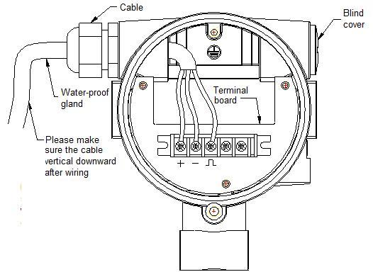
Picture 6.10: Introduction for wiring
7. Display
VFM60 digital vortex flowmeter provide local display and setting, can display several variables on the local multi-functional LCD display. The convertor also have 3 button so clients can do setting on it.
7.1 Instruction of multi-functional LCD display
VFM60 digital vortex flowmeter has a display to indicate “Frequency” “Flow rate” “Total flow”. The VFM60 multi-variable version or a standard VFM60 working with RTD and pressure transmitter can also indicate other variables such as “Temperature” “Pressure” “Density” “Mass flow” etc. Please reference to picture 7.1 below.
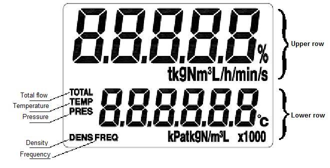
Picture 7.1: LCD display
The LCD display has 2 areas to display the content, the upper row, the lower row. The upper row displays the flow rate/mass flow/standard flow rate. Below the upper row shows the unit of the variable displayed in upper row.
The lower row display indicates other variables, such as frequency/ pressure/ temperature/ density/total flow/ velocity. And below the lower row shows the unit of the variable displayed in lower row.
Please reference to picture 7.2 for display
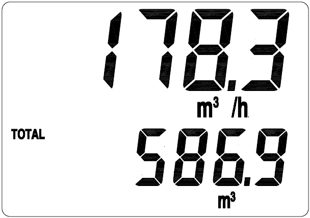
Picture 7.2: Flow rate and total flow
VFM60 multi-variable version or normal version with temperature and pressure compensation, can calculate and display the mass flow of steam, both saturated steam and superheated steam. Please reference to picture 7.3 for mass flow rate displaying.
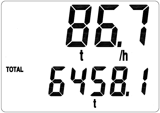
Picture 7.3: Mass flow and total flow of steam displaying
VFM60 multi-variable version or normal version with temperature and pressure compensation can display variables such as temperature/ pressure/ density. Use the switch button to switch to next variable and it will display for 30 seconds.
Please reference to picture 7.4 as a sample of temperature displaying. You can also keep the lower row consistently display a variable by setting. The default variable displayed in lower row is total flow.
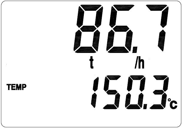
Picture 7.4: Lower row is displaying temperature
You can also set the lower row to display several variables in circular turn.
7.2 Unit of the variable displayed
The variables that can be displayed in lower row and their units that can be displayed are as the chart 7.1 below.
| Subject | Variable | Unit | Circular display code |
| TOTAL | Total flow | Nm3, m3, L, kg or t | 01 |
| TEMP |
Temperature |
℃ |
02 |
| PRES |
Pressure |
MPa or kPa |
03 |
| FREQ |
Frequency |
Hz |
04 |
| DENS |
Density |
kg/ m3 |
05 |
Chart 7.1: The displayed units
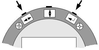
VFM60 series digital vortex flowmeter has three buttons on the top of the displayer, which are:
| [↔] | will be mentioned as “L-R button” below |
| [↕] | will be mentioned as “U-D button” below |
| [↲] | will be mentioned as “Enter button” below) |
Please reference to below picture
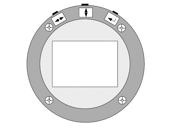
When under working, use “U-D button” to switch the displaying content, use “L-R button” can switch to the left and right digits of total flow. “Enter button” is to display the entire digits of total flow directly.
When the flowmeter is under setting mold, the “L-R button” means move to left and right to select the digit, the “U-D button” means to set the digit to a number, the “Enter button” means “confirm”. All the “Digital setting” and “Code setting” of VFM series vortex flowmeter is made through these 3 buttons.
Please reference to related article for details.
7.4 Total flow displaying
VFM60 can display 9 digits left to decimal point and 3 digits right to it. When the there is more than six digits, the total flow reading will be displayed in two times. One time displays the right digits and the other displays the left digits. You can use the “L-R button” to switch between the right digits and left digits. The left digits will be displayed with a mark of “x1000”.
Please reference to picture 7.6
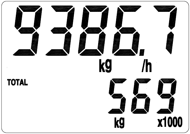
Picture 7.6: Displaying the left digits, a “x1000” mark is displayed
If you want to check the right digits now, please pressure the “L-R button” , the display will be as picture 7.7 below.
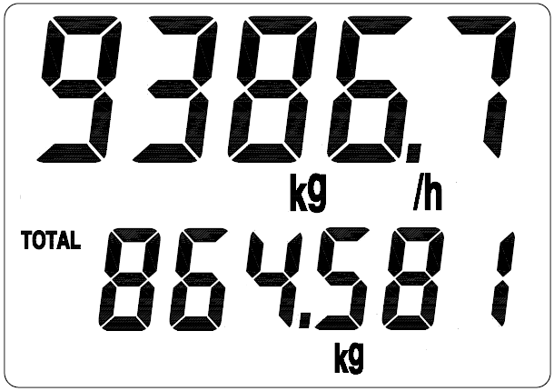
Picture 7.7: Displaying the right digits
According to picture 7.6 and 7.7, the total flow is 569864.581 kg.
7.5 Status
VFM60 series vortex flowmeter have three different statuses as below
- Working status
- Setting status
- Calibration status
When under working status, please follow the instruction in 7.1 to switch the parameter displayed.
When under setting status, you can set the flowmeter, while the flowmeter is still processing, so setting will not have effect on the measuring. In next chapter, there will be instruction of how to do setting.
The calibration of the flowmeter has been finished in manufacture’s lab before delivery, including temperature and pressure calibration and the setting of high-limit and low-limit of 4~20mA simulation output. Thus, customers don't need to do anything.
8. Setting
Note: Every VFM60 digital vortex flowmeters has been set according to requirement before delivery, please do not change setting unless it is necessary and under correct instruction!
VFM60 series digital vortex flowmeter have digital setting and code setting. Use code setting to set parameters such as fluid type, compensation type and output signal. Use digital setting to set parameters related to a number, such as pipe size, flow range, factor.
8.1 How to set
8.1.1 Code setting
Under working status, to enter code setting, please hold “Enter button” then press “U-D button” at the same time. Please reference to picture 8.1.

Picture 8.1: Enter and quit code setting
When in code setting, the first row will display the reference number of the code setting, and the lower row will display the contents of this parameter. The digit that is flashing is the digit under setting. Please reference to picture 8.2, which means C01=02, means fluid type is liquid.
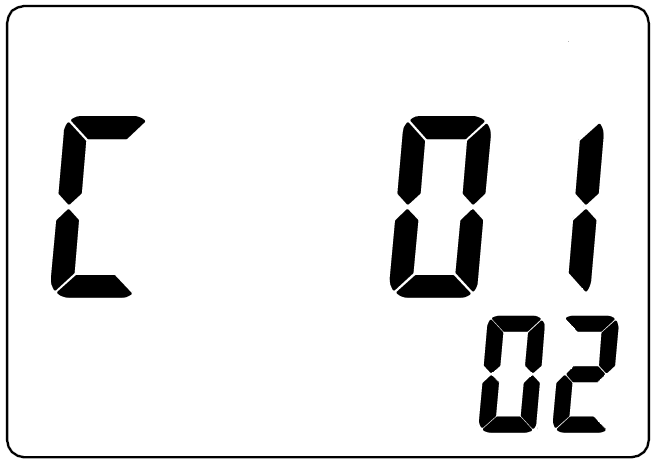
Picture 8.2 Code setting
When under code setting, Now ,user can use “L-R button” to choose which digit on the displayer are to be set , and use “R-D button” to switch the digit to 0~9 . The first time of pressing “Enter button” means to set the lower row. Press “Enter button” again to check if the setting is available. If setting is available, the setting made will be canceled and the display will not flash, then press “L-R button” or “U-D button” to set again. When display is not flashing, pressure “Enter button” to save and go to next setting.
If want to quit code setting, same as entering, please hold “Enter button” then press “U-D button” at the same time.
8.1.2 Digital setting
Under working status, to enter code setting, please hold “Enter button” then press “L-R button” at the
same time. Please reference to picture 8.3.
Picture 8.3: Enter or quit digital setting
When in digital setting, the first row will display the reference number of the digital setting, and the lower row will display the contents of this parameter. The digit that is flashing is the digit under setting. Please reference to picture 8.4, which means D001=1.60000, max pressure is 1.6 (unit according to other setting.)
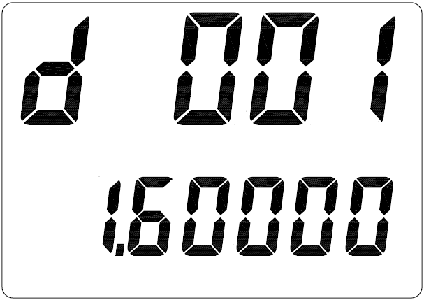
Picture 8.4: Digital setting
When under digital setting, Now, user can use “L-R button” to choose which digit on the displayer are to be set , and use “R-D button” to switch the digit to 0~9 . The first time of pressing “Enter button” means to set the lower row. Press “Enter button” again to check if the setting is available. If setting is available, the setting made will be canceled and the display will not flash, then press “L-R button” or “U-D button” to set again. When display is not flashing, pressure “Enter button” to save and go to next setting.
If want to quit code setting, same as entering, please hold “Enter button” then press “U-D button” at the same time.
8.2 Setting list
Please check chart 8.1 and 8.2 for code and digital setting address list.
Chart 8.1: Code setting address
|
Code setting address |
Item |
Code |
Description of code |
|
01 |
Fluid |
00 |
Steam |
|
01 |
Gas |
||
|
02 |
Liquid |
||
|
02 |
Density compensation |
00 |
Volume flow display, no density compensation |
|
01 |
Density preset |
||
|
02 |
Pressure compensation (for saturated steam pressure not larger than 20Mpa |
||
|
03 |
Temperature compensation (For saturated steam) |
||
|
04 |
Temperature and pressure compensation (For superheated steam) |
||
|
05 |
ρ=A+BP (Pressure compensation) |
||
|
06 |
ρ=A+BT (Temperature compensation) |
||
|
07 |
AGA-NX-19 to calculate compressibility factor |
||
|
08 |
Temperature and pressure compensation to get normal condition flow rate of gas |
||
|
09 |
AGA-8 to calculate compressibility factor |
||
|
10 |
Air compressor output flow analysis |
||
|
05 |
Output |
01 |
Pulse (Please reference to D008 for K factor) |
|
02 |
4~20mA or HART@4~20mA |
||
|
03 |
200-1000HZ frequency output, set what to output in C06 |
||
|
04 |
frequency output for total flow, set factor in D013 |
||
|
06 |
4~20mA or 4~20mA@HART or 200-1000Hz output parameter |
00 |
Flow rate |
|
01 |
Temperature |
||
|
02 |
Pressure |
||
|
07 |
Damping |
01~99 |
1~99 seconds |
|
08 |
Instrument number |
00~99 |
For Modbus |
|
00~15 |
For Modbus or HART communication |
||
|
09
|
Baud rate
|
01 |
1200 no parity 1 stop bit |
|
02 |
1200 even parity 1 stop bit |
||
|
03 |
2400 no parity 1 stop bit |
||
|
04 |
2400 even parity 1 stop bit |
||
|
05 |
4800 no parity 1 stop bit |
||
|
06 |
4800 even parity 1 stop bit |
||
|
07 |
9600 no parity 1 stop bit |
||
|
08 |
9600 even parity 1 stop bit |
||
|
09 |
19200 no parity 1 stop bit |
||
|
10 |
19200 even parity 1 stop bit |
||
|
11 |
1200 odd parity 1 stop bit |
||
|
12
13 |
2400 odd parity 1 stop bit
4800 odd parity 1 stop bit |
||
|
14 |
9600 odd parity 1 stop bit |
||
|
15 |
19200 odd parity 1 stop bit |
||
|
16 |
38400 no parity 1 stop bit |
||
|
17 |
38400 even parity 1 stop bit |
||
|
18 |
38400 odd parity 1 stop bit |
||
|
19 |
57600 no parity 1 stop bit |
||
|
20 |
57600 even parity 1 stop bit |
||
|
21 |
57600 odd parity 1 stop bit |
||
|
22 |
115200 no parity 1 stop bit |
||
|
23 |
115200 even parity 1 stop bit |
||
|
24 |
115200 odd parity 1 stop bit |
||
|
10
|
Time unit for flow rate
|
00 |
/s |
|
01
02 |
/min
/h |
||
|
03 |
/day |
||
|
11
|
Mass unit
|
01 |
kg |
|
02 |
ton |
||
|
03 |
lb |
||
|
12
|
Volume unit for flow rate
|
01 |
m3 |
|
02 |
L |
||
|
03 |
ft3 |
||
|
04 |
US gal |
||
|
05 |
UK gal |
||
|
13
|
Pressure unit
|
01 |
Mpa |
|
02 |
Kpa |
||
|
03 |
Psi |
||
| 14 |
Temperature unit
|
01 | ℃ |
|
02 |
℉ | ||
|
03 |
K | ||
| 15 |
Right digits number for total flow
|
00~05
|
00:No right digits for total flow |
|
01~05:1~5 right digits for total flow |
|||
|
16 |
1st row display parameter
|
01 |
Flow rate |
|
02 |
Percentage of flow rate to flow range |
||
| 17 |
lower row display parameter
|
00 |
No display |
|
01 |
Total flow |
||
|
02 |
Temperature |
||
|
03 |
Pressure |
||
|
04 |
Density |
||
|
05 |
Frequency | ||
| 18 |
Density unit
|
01 |
Kg/m3 |
|
02 |
lb/ft3 |
||
| 19 |
Decimal of flow rate |
00~04 |
00: No right digits for flow rate 01~04: 1~4 right digits for flow rate |
| 20 | Decimal of temperature | 00~04 |
00: No right digits for temperature 01~04: 1~4 right digits for flow rate |
| 21 | Decimal of pressure | 00~04 |
00: No right digits for pressure 01~04: 1~4 right digits for pressure |
| 30 | Time space for circle display | 00~30 | 00:circle display off |
| 1~30:1~30 seconds between the display of different parameter | |||
| 31 | First parameter displayed in circle display | 00~05 |
00:circle display off 01~05:see chart 7.1 |
| ⫶ | ⫶ | ⫶ | …. |
| 35 | Last parameter displayed in circle display | 00~05 | Same as above |
| 38 | Sequence of float (under RS485 communication) | 01 | LL_LH_HL_HH |
| 02 | HH_HL_LH_LL | ||
| 03 | LH_LL_HH_HL | ||
| 04 | HL_HH_LL_LH | ||
| 47 | Password function | 00 | off |
| 01 | on | ||
| 48 | Set password | 00 | Keep the password |
| 01 | Change the password | ||
| 49 | Spectrum analyzing checking | 00 | Working status |
| 12 | spectrum analyzing checking | ||
| 50 | Total flow reset | 00 | Reset total flow to 0 |
| 01 | Default | ||
| 55 | Times of over total flow | 00~99 | For reading only |
| 60 | Restore to backup date | 06 | Restore to backup date |
| 61 | Save setting backup | 16 | Save current setting for backup |
- Note:
- If the unit of flow rate is changed or measurement changed from flow rate to mass flow, users can reset the total flow to 0 or record the current total flow.
- Total flow=(time of over total flow)* (max display of total flow)+(current total flow reading)
Chart 8.2: Digits setting address
|
Digital setting address |
Item |
Code |
Description of code |
|
001 |
Max pressure |
[-99999,999999] |
Max input/output pressure |
|
002 |
Min pressure |
[-99999,999999] |
Min input/output pressure |
|
003 |
Max temperature |
[-99999,999999] |
Max input/output temperature |
|
004 |
Min temperature |
[-99999,999999] |
Min input/output temperature |
|
005 |
Preset density |
(0,999999] |
When C02=01, the meter will use this density, unit according to setting |
|
008 |
K factor |
(0,999999] |
K factor according to calibration result, unit is pulses/Liter. Flow=3.6*freq/K |
|
009 |
Max flow rate |
(0,999999] |
unit is same as flow rate, Max/min flow rate of 4~20mA and 200~1000Hz output |
|
010 |
Min flow rate |
[0,999999] |
|
|
011 |
Max frequency |
[0,999999] |
Up-limit of frequency (Hz) output |
|
012 |
Min frequency |
[0,999999] |
Down-limit of frequency (Hz) output |
|
013 |
pulse factor for total flow |
(0,999999] |
used when freq output of total flow |
|
014 |
Ambient pressure |
(0,999999] |
Unit according to setting |
|
015 |
Pipe size |
(0,999999] |
unit is mm |
|
021 |
Cut off small signal |
[0,999999] |
unit is Hz |
|
022 |
Standard temperature |
[0,999999] |
unit is °C; for standard flow rate calculation |
|
023 |
Temperature of air compressor inlet |
[-40,999999] |
Unit is °C, for air compressor flow outlet analysis |
|
024 |
Pressure of air compressor inlet |
(0,999999] |
Unit is Mpa, for air compressor flow outlet analysis |
|
025 |
Temperature preset |
[-99999,999999] |
Unit is °C |
|
026 |
Resonance frequency starting frequency |
(0,999999] |
For high speed steam measure use |
|
027 |
Resonance frequency ending frequency |
(0,999999] |
For high speed steam measure use |
|
030 |
Relative density of compressibility factor |
[0.55,0.90] |
For calculation of compressibility factor of natural gas |
|
031 |
mol% of N2 and H2 |
[0,0.1] |
For calculation of compressibility factor of natural gas, eg.if 1%, please input 0.01 |
|
032 |
mol% of CO2 |
[0,0.3] |
For calculation of compressibility factor of natural gas, eg.if 1%, please input 0.01 |
|
033 |
Higher heating value |
[20,48] |
MJ/mol, For calculation of compressibility factor of natural gas |
Note: Max freq output=10KHz, the pulse factor for total flow should be set properly set according to the current total flow.
8.3 Example of setting
Sample: For vortex flowmeter VFM60, measure gas in DN50 pipe, K factor= 7.802P/L, density preset, mass flow display unit is kg/h. 4~20mA output with a flow range of 0~4000kg/hr
|
Code setting |
Address |
Code |
Description |
|
01 |
01 |
gas |
|
|
02 |
01 |
Density preset |
|
|
05 |
02 |
4~20mA analog output |
|
|
Digital setting |
005 |
2.0000 |
Density=2 |
|
008 |
7.802 |
K factor=7.802 P/L |
|
|
009 |
4000 |
Flow rate of 20mA |
|
|
010 |
0 |
Flow rate of 4mA |
|
|
015 |
50 |
Pipe size=50mm |
8.4 Password setting instruction
There is no password set in default in a new VFM60 digital vortex flowmeter ,users can set a password following instruction below.
Enter code setting, set C47=01, confirm and quit then enter the password setting interface as picture 8.5
Picture 8.5: Password setting interface
To set a new password, users have to input the correct password twice, the password will become effective only if the both inputs are the same; or users have to input again. If the power is off during a password setting process, the password will be 2000 as default. When a password becomes effective, users have to input the correct password before he can set the flowmeter, please reference to picture 8.6.
If users input incorrect password 3 times consistently, the display will come back to normal display
Picture 8.6: Password input
If a password has been set to a VFM60 vortex flowmeter, users can enter code setting C48=01 to set a new password.
9. Instruction of Modbus Communication
9.1 Interface regulation
- The communication interface should be RS485, the range of Baud rate should be 1200~115200.
- The wiring terminal is “A” and “B”.
- The communication should comply with MODBUS-RTU statute.
- The combination of a communication signal: Address code - function code – date segment – CRC calibration code. The distance between two characters should not be longer than one character, or it will be considered as the beginning of a new message or the end of a old message. The message is combined with hexadecimal arrays.
- Definition of the dates: Please reference to the chart 9.1 below.
Chart 9.1: Address of the displayed date
|
Register address |
Usage |
Nature |
Date type |
|
0~1 |
Flow rate |
Read only |
Float |
|
2~3 |
Frequency |
Read only |
Float |
|
4~5 |
Reserved |
Read only |
Float |
|
6~7 |
Pressure |
Read only |
Float |
|
8~9 |
Temperature |
Read only |
Float |
|
10~11 |
Density |
Read only |
Float |
|
12~13 |
Reserved |
Read only |
Float |
|
14~15 |
Reserved |
Read only |
Float |
|
16~17 |
Reserved |
Read only |
Float |
|
18~19 |
Reserved |
Read only |
Float |
|
20~21 |
Reserved |
Read only |
Float |
|
22~23 |
Reserved |
Read only |
Float |
|
24~25 |
Total flow |
Read only |
Float |
The displayable date including flow rate, frequency, pressure, temperature, density and total flow, if the meter do not have density compensation, then the reading of pressure and temperature will both be 0. The date of the parameters in above chart can be read by using function code 03 according to the address above and shifting.
The addresses of code setting are as below.
Chart 9.2: Address of code setting
|
Register |
Usage |
Range |
Nature |
Date type |
|
1000 |
Fluid type C01 |
1~2 |
Read only |
Short |
|
1001 |
Density compensation C02 |
0~9 |
Read/Write |
Short |
|
1004 |
Output C05 |
1~4 |
Read/Write |
Short |
|
1005 |
200-1000Hz output parameter C06 |
1~3 |
Read/Write |
Short |
|
1006 |
Damping C07 |
1~99 |
Read/Write |
Short |
|
1007 |
Instrument number C08 |
Hart(0~15) MB(1~99) |
Read |
Short |
|
1008 |
Baud rate C09 |
1~24 |
Read |
Short |
|
1009 |
Unit of time C10 |
0~2 |
Read/Write |
Short |
|
1010 |
Mass unit C11 |
1~3 |
Read/Write |
Short |
|
1011 |
Volume unit C12 |
1~5 |
Read/Write |
Short |
|
1012 |
Pressure unit C13 |
1~4 |
Read/Write |
Short |
|
1013 |
Temperature unit C14 |
1~3 |
Read/Write |
Short |
|
1014 |
Right digits number for total flow C15 |
0~5 |
Read/Write |
Short |
|
1015 |
1st row display parameter C16 |
1~2 |
Read/Write |
Short |
|
1016 |
lower row display parameter C17 |
0~5 |
Read/Write |
Short |
|
1017 |
Density unit C18 |
1~2 |
Read/Write |
Short |
|
1029 |
Time space for circle display C30 |
0~30 |
Read/Write |
Short |
|
1030 |
First parameter displayed in circle display C31 |
0~5 |
Read/Write |
Short |
|
1031 |
Second parameter displayed in circle display C32 |
0~5 |
Read/Write |
Short |
|
1032 |
Third parameter displayed in circle display C33 |
0~5 |
Read/Write |
Short |
|
1033 |
Fourth parameter displayed in circle display C34 |
0~5 |
Read/Write |
Short |
|
1034 |
fifth parameter displayed in circle display C35 |
0~5 |
Read/Write |
Short |
|
1035 |
C36 |
0~1 |
Read/Write |
Short |
|
1036 |
C37 |
0~10 |
Read/Write |
Short |
|
1037 |
Sequence of float C38 |
1~4 |
Read/Write |
Short |
|
1046 |
Password function C47 |
0~1 |
Read |
Short |
|
1047 |
Set password C48 |
0~1 |
Read |
Short |
|
1048 |
Spectrum analyzing checking C49 |
0~12 |
Read/Write |
Short |
|
1049 |
Total flow reset to 0 C50 |
0~1 |
Read/Write |
Short |
|
1050 |
C51 |
0~0 |
Read/Write |
Short |
|
1051 |
C52 |
0~99 |
Read/Write |
Short |
|
1052 |
C53 |
0~0 |
Read/Write |
Short |
|
1053 |
C54 |
0~0 |
Read/Write |
Short |
|
1054 |
Times of over total flow C55 |
0~0 |
Read only |
Short |
|
1059 |
Restore to backup date C60 |
0~99 |
Read/Write |
Short |
|
1060 |
Save setting backup C61 |
0~99 |
Read/Write |
Short |
Users can use function code 04 and 06 to access to the address for code setting above.
Digital setting address is as below.
Chart 9.3: Address of digital setting
|
Register |
Usage |
Restriction of modification |
Nature |
Date type |
|
2000~2001 |
D001 Max pressure |
-1e5~1e6 |
Read/Write |
Float |
|
2002~2003 |
D002 Min pressure |
-1e5~1e6 |
Read/Write |
Float |
|
2004~2005 |
D003 Max temperature |
-1e5~1e6 |
Read/Write |
Float |
|
2006~2007 |
D004 Min temperature |
-1e5~1e6 |
Read/Write |
Float |
|
2008~2009 |
D005 Density |
0~1e6 |
Read/Write |
Float |
|
2014~2015 |
D008 K factor |
0~1e6 |
Read/Write |
Float |
|
2016~2017 |
D009 Max flow rate |
0~1e6 |
Read/Write |
Float |
|
2018~2019 |
D010 Min flow rate |
0~1e6 |
Read/Write |
Float |
|
2024~2025 |
D013 Factor for total flow output |
0~1e6 |
Read/Write |
Float |
|
2026~2027 |
D014 Ambient pressure |
0~1e6 |
Read/Write |
Float |
|
2028~2029 |
D015 Pipe size |
0~1e6 |
Read/Write |
Float |
|
2040~2041 |
D021 Cut off small signal |
0~1e6 |
Read/Write |
Float |
|
2058~2059 |
D030 Specific density |
[0.55,0.90] |
Read/Write |
Float |
|
2060~2061 |
D031 mol% of N2 and H2 |
[0,0.1] |
Read/Write |
Float |
|
2062~2063 |
D032 mol% of CO2 |
[0,0.3] |
Read/Write |
Float |
|
2064~2065 |
D033 Higher heating value |
[20,48] |
Read/Write |
float |
The chart above indicates the register address, usage of the register, restriction of modification, read/write nature and date type. The register above are all holding register, the supporting function code is 03,04,06,16 function code.
9.2 Commends
Function code 03 and 04 are the codes supported for reading the registers. Function code 06 is for writing one register. Function code 16 is for writing multi registers. Function code 06 is only supported for writing short date. Function code 16 is supported for writing both short date and float date.
Function code 03 – Read register
|
Request |
Response |
|
01 : Address |
01: Address |
|
03 : Function code |
03 : Function code |
|
00 : Register address higher |
04 : Quantity of bit |
|
00 : Register address lower (display the address) |
80 : Date 1 |
|
00 : Register number higher |
04 : Date 2 |
|
02 : Register number lower |
80 : Date 3 |
|
CRCL : CRC Parity code lower |
80 : Date 4 |
|
CRCH :CRC parity code higher |
CRCL : CRC Parity code lower |
|
|
CRCH :CRC parity code higher |
Note: To read a float date, the quantity of the register address and its value have to be even, or response will be error.
Function code 04 – Same as function code 03
Function code 06 – write one register
|
Request |
Response |
|
01 : Address |
01: Address |
|
06 : Function code |
06 : Function code |
|
00 : Register address higher |
00 : Register address higher |
|
01 : Register address lower (code setting address) |
01 : Register address lower |
|
00 : Value higher |
00 : Value higher |
|
04 : Value lower |
04 : Value lower |
|
CRCH :CRC parity code higher |
CRCH :CRC parity code higher |
|
CRCL : CRC Parity code lower |
CRCL : CRC Parity code lower |
Note: Function code is only supported for writing short dater.
Function code 16- write multi register.
|
Request |
Response |
|
01 : Address |
01: Address |
|
10H : Function code |
10H : Function code |
|
00 : Register address higher |
00 : Register address higher |
|
01 : Register address lower (digital setting address) |
01 : Register address lower |
|
00 : Quantity of register higher |
00 : Quantity of register higher |
|
02 : Quantity of register lower |
02 : Quantity of register lower |
|
04 : Quantity of values |
CRCH :CRC parity code higher |
|
86h : Value 1 |
CRCL : CRC Parity code lower |
|
00 : Value 2 |
|
|
00 : Value 3 |
|
|
48H: Value 4 |
|
|
CRCH :CRC parity code higher |
|
|
CRCL : CRC Parity code lower |
|
Note: Function code 16 is supported to write both short date and float date. But for float date, the first register address and the quantity of the registers must be even, or writing is not allowed.
9.3 Calculation of CRC parity code
|
Request |
Response |
|
01 : Address |
N1 CRC=0FFFFH is initial value |
|
10 : Function code |
N2 XOR operation the CRCL and N1 |
|
00 : Register address higher |
N3 CRC move 1 bit right , if move out is 1 bit |
|
01 : Register address lower |
N4 CRC=CRC XOR A001H |
|
00 : Register quantity higher |
N5 if move out is 0 , CRC=CRC |
|
04 : Register quantity lower |
N6 Move right for 8 times to finish the N1 calculation |
|
04 : Date quantity |
N7 … |
|
80 : Date 1 |
N8 XOR operation the CRCL and N11 |
|
04 : Date 2 |
N9 CRC move 1 bit right , if move out is 1 bit |
|
80 : Date 3 |
N10 CRC=CRC XOR A001H |
|
80 : Date 4 |
N11 if move out is 0 , CRC=CRC |
|
CRCL : CRC Parity code lower |
Move right for 8 times to finish the N11 calculation |
|
CRCH :CRC Parity code higher |
Get the CRC calibration value |
9.4 The float date format of the instrument
The storage sequence of 4 bits float format is as below:
| Address | 0 | 1 | 2 | 3 |
| Content | MMMMMMMM | MMMMMMMM | EMMMMMMM |
SEEEEEEEE |
Use IEEE standard method, do not store 1 on top digit, if top digit is 1, means negative; if top digit is 0, means positive. So the 23 mantissas and a 1 on top digit, which is concealed, constitute a 24 bits fixed point true form decimal, which is a decimal have mantissas less than 1 and more than or equal to 0.5. The lowest 8 bits are exponent-marker using shift code method. The exponent marker equals to the actual value minus 127. For example: 7=86H-7FH, -10=75H-7FH
e.g.: 100=0x00,0x00,0x42,0xc8
-100=0x00,0x00, 0xc2,0xc8
0=0x00.0x00.0x00.0x00 (exponent-marker is 0, the number is 0)
9.5 The sequence of the float date bytes of instrument
Code setting C38 is used for setting the sequence of the float date bytes of instrument. Float date will occupy 4 bytes (2 registers). To set the bytes order of float date, please modify register :
1: LL_LH_HL_HH the lower 16 bytes registers come first, the lower 8 bytes within the 16 bytes registers come first.
eg: 100=0x00,0x00, 0xc8, 0x42
-100=0x00,0x00,0xc8,0xc2
2: HH_HL_LH_LL the higher 16 bytes registers come first, the higher 8 bytes within the 16 bytes registers come first.
eg: 100=0x42,0xc8,0x00,0x00
-100=0xc2,0xc8 ,0x00,0x00
3: LH_LL_HH_HL the lower 16 bytes registers come first, the higher 8 bytes within the 16 bytes registers come first.
eg: 100=0x00,0x00,0x42,0xc8
-100=0x00,0x00,0xc2,0xc8
4: HL_HH_LL_LH the higher 16 bytes registers come first, the lower 8 bytes within the 16 bytes registers come first.
eg: 100=0xc8,0x42,0x00,0x00
-100=0xc8,0xc2,0x00,0x00
9.6 Modbus error response
When the host sends a command and asks for a correct response, one of below three is going to happen:
1) If the command from the host is correct and processable, the flow meter will give a correct response.
2) If the flowmeter received a command, but detected parity, the error of LRC and CRC will cause no response. The host will process a overtime commend.
3) If the flowmeter received a correct command, but can not process it (read or write a none-existing register etc.), the flowmeter will send a error response
A error response has two byte sections to show its difference from a correct response.
Function code section: In a correct response, the flowmeter will copy the origin function code sent from the host, and the highest bytes of them are all 0(all function codes are smaller than 0x80). In a error response, the flowmeter will set the highest bytes to 1. The host can detect the error code and know the content of the error when it detect that the highest bytes of function codes are 1.
Value section: In a error response, the flowmeter will reply a byte as the error code to definite the content of the error. Please reference to the chart below for the error codes and its definition:
|
Code |
Name |
Meaning |
|
01 |
Illegal function code |
Flowmeter can not process the function code in a command. Maybe this function code can only be used on a new device, or it can also indicate that the flowmeter is under error statues. |
|
02 |
Illegal address |
The flowmeter can not process with the address in the command. The initiate address plus address diversion are higher than the highest address. |
|
03 |
Illegal contents of value |
The content of the value in the command is not acceptable for the flowmeter. |
|
04 |
Flow meter function failed |
An unrecoverable failure happened when the flowmeter is trying to response. |
|
05 |
Response |
The flow meter will take a long while to process the command. So response this error code to prevent the host from processing a overtime command. |
|
06 |
Flowmeter is busy |
To advise the host that the flowmeter is processing a command which will takes a long time. So the host should resend the command when the flowmeter is free. |
9.7 Examples of communication
The flowmeter’s instrument Modbus address is 01, baud rate=4800 (C08=01, C09=05, C38=02).
Example 1: Read flow rate F,F=916.49 (4 bytes float)
Host command: 01 03 00 00 00 02 C4 0B
Flowmeter response: 01 03 04 44 65 1F CE 77 78
Example 2: Read total flow
Host command: 01 03 00 24 00 02 84 00
Flowmeter reponse:01 03 04 44 9D 1E 3F 36 9D
Example 3: Read all the value displayed on the flowmeter, including flow rate, frequency, pressure, temperature, density, total flow ….. all together 13 value (52 bytes)
Host command: 01 03 00 00 00 1A c4 01
- 44 65 1F CE(flow rate=916.49)
- 42 48 00 00(frequency=50)
- 00 00 00 00(reserved=0)
- 00 00 00 00(pressure=0)
- 00 00 00 00(temperature=0)
- 3F 80 00 00(density=1.00)
- 00 00 00 00(reserved=0)
- 00 00 00 00(reserved)
- 00 00 00 00(reserved)
- 00 00 00 00(reserved)
- 00 00 04 E8(reserved=1256)
- 00 00 00 00(reserved=0)
- 44 9D 1E 3F(total flow in float=1256.94)
- 5A (CRCL)
- 91 (CRCH)
10. Introduction of HART communication protocol
10.1 HART commands
10.1.1 Command 0: Read transmitter unique identifier
Command format
Return to the expansion device type code, version number and identification number
Request: None
Response:
Byte 0: 254
Byte 1: Manufacture’s ID
Byte 2: Manufacture’s device type
Byte 3: Number of request preambles
Byte 4: Revision level of universal command
Byte 5: Revision level of transmitter document
Byte 6: Software revision level
Byte 7: Hardware revision level
Byte 8: Flags, none defined at this time
Byte 9-11: Device Identification Number
Test of command
Send 0 command: FF FF FF FF FF 02 80 00 00 82; to request information of the instrument
Receive 0 command: FF FF FF FF FF 06 80 00 0E 00 00 FE 1A 1A 05 05 00 00 00 00 AD 18 8C 4F
10.1.2 Command 1: Read primary variable value (PV)
Command format:
Return to primary variable value in float.
Request: None
Response:
Byte 0: Primary variable unit code
Byte 1-4: Primary variable
Remark: The unit code is 75:kg/hour, 19:m3/hour.
Set primary command to flow rate.
Test of command:
Send command 1: FF FF FF FF FF 82 9A 1A AD 18 8C 01 00 3A ;to read the IEEE754 float value of primary variable.
Receive command 1:FF FF FF FF FF 86 9A 1A AD 18 8C 01 07 00 00 13 00 00 00 00 2A
10.1.3 Command 2: Read primary variable’s current and percentage value
Command format:
Read the current and percent of the primary variable, the current of primary variable always match the AO current output of the instrument. Percent is not restricted within 0~100%, if it is beyond the limit of primary variable, it will find the limit of the transmitter.
Request: None
Response:
Byte 0-3: Analog output current mA, IEEE754
Byte 4-7: Percent of range , IEEE 754.
Test of command:
Send command 2: FF FF FF FF FF 82 9A 1A AD 18 8C 02 00 39 ; to read the current and primary variable percent of range.
Receive command 2: FF FF FF FF FF 86 9A 1A AD 18 8C 02 0A 00 00 40 80 00 00 00 00 00 00 F7
10.1.4 Command 3: Read primary variable current and dynamic variables
Command format:
Read the current of primary variable and 4 preset dynamic variables at maximum. The current of primary variable always match the AO output current of the instrument. Every type of device has a definition on a relative dynamic variable, for example the secondary variable is temperature sensor.
Request: None
Response:
Byte 0-3: Analog output current mA, IEEE 754
Byte 4: Primary variable unit code
Byte 5-8: Primary variable, IEEE 754
Byte 9: Secondary variable unit code
Byte 10-13: Secondary variable, IEEE 754
Byte 14: Tertiary variable unit code
Byte 15-18: Tertiary variable, IEEE 754
Byte 19: Quaternary variable unit code
Byte 20-23: Quaternary variable, IEEE 754
Remark: Primary variable is flow rate. The unit code is 75:kg/hour, 19:m3/hour;
Secondary variable is total flow. The unit code is 61:kg, 43:m3;
Tertiary variable is frequency. The unit is Hz;
Quaternary variable is temperature. The unit is 32: ℃;
Test of command:
Send command 3: FF FF FF FF FF 82 9A 1A AD 18 8C 03 00 38; to read dynamic variables
Receive command 3: FF FF FF FF FF 86 9A 1A AD 18 8C 03 1A 00 00 40 80 00 00 13 00 00 00 00 2B 48 33 5A 4B 26 00 00 00 00 20 00 00 00 00 B2
10.1.5 Command 6: Write polling address
Command format:
It is a date link management command. This command writes a polling address to the device. This address is used to control the AO of primary variable and providing of device ID.
Only when the polling address of the instrument is 0, that the AO output of primary variable is available. If the address is 1~15, AO will be not activated and will not response, AO will be minimum value; transmission status will be the 3rd statue------primary variable AO fixed; max and min alarm not implemented. If polling address is write back to 0, AO will be activated again and will response.
Request:
Byte 0: Device polling address
Response:
Byte 0: Device polling address
Test of command:
Send command 6: FF FF FF FF FF 82 9A 1A AD 18 8C 06 01 00 3C ; to write POLLING ADDRESS
Receive command 6:FF FF FF FF FF 86 9A 1A AD 18 8C 06 03 00 00 00 3A
10.1.6 Command 11: Read unique identifier associated with tag
Command format:
It is a date link management command. This command will return the device type, revision level
and device identification number of the device which matches to the tag. Process the command upon
receipt of the expansion address or broadcast address. The expansion addresses in command and
response are the same.
Request:
Byte 0-5: Tag, Packed ASCI
Response:
Byte 0: Device type code for expansion
Byte 1: Manufacture Identification code
Byte 2: Manufacture device type
Byte 3: Number of request preambles
Byte 4: Revision level of universal command
Byte 5: Revision level of transmitter document
Byte 6: Software revision level
Byte 7: Hardware revision level
Byte 8: Flags, none defined at this time.
Byte 9-11: Device identification number
Test of command:
Send command 11: FF FF FF FF FF 82 9A 1A AD 18 8C 0B 00 30 ; Read relevant info of the device such as unique identifier associated with tag
Receive command 11: FF FF FF FF FF 86 9A 1A AD 18 8C 0B 0E 00 00 FE 1A 1A 05 05 00 00 00 00 AD 18 8C FD
10.1.7 Command 12: Read message
Command format:
To read message
Request: None
Response:
Byte 0-23: Message
Test of command:
Send command 12:FF FF FF FF FF 82 9A 1A AD 18 8C 0C 00 37 ; read message
Receive command 12:FF FF FF FF FF 86 9A 1A AD 18 8C 0C 1A 00 00 59 00 74 D6 05 8F 49 41 58 80 42 47 25 40 4C 81 04 8F 0C 54 D3 3D 28 20 10
10.1.8 Command 13: Read tag, descriptor, date
Command format:
Read device tag, description and date.
Request: None
Response:
Byte 0-5: Tag, ASCII
Byte 6-17: Descriptor, ASCII
Byte 18-20: Date: day, month, year
Test of command:
Send command 13:FF FF FF FF FF 82 9A 1A AD 18 8C 0D 00 36 ;read device tag, descriptor and date
Receive command 13:FF FF FF FF FF 86 9A 1A AD 18 8C 0D 17 00 00 50 11 E0 82 08 20 58 F4 94 15 88 06 30 F5 CD 15 41 52 0F 01 6F E2
10.1.9 Command 14: Read primary variable sensor information: device serial number and limits
Command format:
Read device information
Request: None
Response:
Byte 0-2: Sensor serial number MSB, 24-BIT unsigned integer
Byte 3: Flow rate unit
Byte 4-7: Upper sensor limit of flow rate
Byte 8-11: Lower sensor limit of flow rate
Byte 12-15: Minimum span of flow rate
Test of command:
Send command 14: FF FF FF FF FF 82 9A 1A AD 18 8C 0E 00 35; to read primary sensor serial number and limits.
Receive command 14: FF FF FF FF FF 86 9A 1A AD 18 8C 0E 12 00 00 00 00 00 13 43 96 00 00 00 00 00 00 38 D1 B7 17 AC
10.1.10 Command 15: Read primary variable output information
Command format:
Read Primary variable alarm select code, primary variable transfer code, primary variable range values units code, primary variable upper and lower range value, primary variable damping value, write protect code and private label distributor code VIII
Request: None
Response:
Byte0: Alarm select code
Byte1: Primary variable transfer function code
Byte2: Primary variable range values unit code
Byte3-6: Primary variable upper range value, IEEE754
Byte7-10: Primary variable lower range value, IEEE754
Byte11-14: Primary variable damping value, IEEE754,units of seconds
Byte15: Write protect code
Byte16: Private Label Distributor Code
Test of command:
Send command 15:FF FF FF FF FF 82 9A 1A AD 18 8C 0F 00 34; Read primary variable output information
Receive command 15:FF FF FF FF FF 86 9A 1A AD 18 8C 0F 13 00 00 00 00 13 43 96 00 00 00 00 00 00 42 20 00 00 FB 12 6E
10.1.11 Command 16: Read final assembly number
Command format:
Read final assembly number.
Request: None
Response:
Byte 0-2: Final assembly number
Test of command:
Send command 16:FF FF FF FF FF 82 9A 1A AD 18 8C 10 00 2B; Read final assembly number
Receive command 16: FF FF FF FF FF 86 9A 1A AD 18 8C 10 05 00 00 A8 36 81 35
10.1.12 Command 17: Write message
Command format:
Write message
Request:
Byte 0-23: Message
Response:
Byte 0-23: Message
Test of command:
Send command 17:FF FF FF FF FF 82 9A 1A AD 18 8C 11 18 00 01 02 03 04 05 06 07 08 09 0A 0B 0C 0D 0E 0F 10 11 12 13 14 15 16 17 32 ;message
Receive command 17:FF FF FF FF FF 86 9A 1A AD 18 8C 11 1A 00 00 00 01 02 03 04 05 06 07 08 09 0A 0B 0C 0D 0E 0F 10 11 12 13 14 15 16 17 34
10.1.13 Command 18: Write tag, descriptor, date
Command format:
Write tag, descriptor, date.
Request:
Byte 0-5: Tag, ASCII
Byte 6-17: Descriptor, ASCII
Byte 18-20: Date: day, month, year
Response:
Byte 0-5: Tag, ASCII
Byte 6-17: Descriptor, ASCII
Byte 18-20: Date: day, month, year
Test of command:
Send command 18: FF FF FF FF FF 82 9A 1A AD 18 8C 12 15 00 00 00 00 00 00 00 00 00 00 00 00 00 00 00 00 00 00 00 00 00 3C
Receive command 18:FF FF FF FF FF FF 86 9A 1A AD 18 8C 12 17 00 00 00 00 00 00 00 00 00 00 00 00 00 00 00 00 00 00 00 00 00 00 00 3A
10.1.14 Command 19: Write final assembly number
Command format:
Write final assembly number
Request:
Byte 0-2: Final assembly number
Response:
Byte 0-2: Final assembly number
Test of command:
Send command 19: FF FF FF FF FF 82 9A 1A AD 18 8C 13 03 01 02 03 2B ;
Receive command 19: FF FF FF FF FF 86 9A 1A AD 18 8C 13 05 00 00 01 02 03 29
10.1.15 Command 34: Write primary variable damping value
Command format:
Write primary variable damping value. If value is not acceptable, will revert with alarm.
Request:
Byte 0-3: Damping value, IEEE754
Response:
Byte 0-3: Actual damping value, IEEE754
Test of command:
Send command 34: FF FF FF FF FF 82 9A 1A AD 18 8C 22 04 40 00 00 00 5D; Write primary variable damping value
Receive command 34: FF FF FF FF FF 86 9A 1A AD 18 8C 22 06 00 00 40 00 00 00 5B
10.1.16 Command 35: Write primary variable range values
Command format:
The upper and lower limits of primary variable are independent. The primary variable range unit value that this command received has no effect on the primary variable unit value. The primary value range value will be returned in the unit received.
Most device allows that the measurement range upper limit lower than lower limit ,to support the device to reverse output.
Request:
Byte 0: Primary variable upper and lower range value unit code
Byte 1-4: Primary variable upper range limit, IEEE 754
Byte 5-8: Primary variable lower range limit, IEEE 754
Response:
Byte 0: Primary variable upper and lower range value unit code
Byte 1-4: Primary variable upper range limit, IEEE 754
Byte 5-8: Primary variable lower range limit, IEEE 754
Test of command:
Send command 35: FF FF FF FF FF 82 9A 1A AD 18 8C 23 09 13 40 00 00 00 40 00 00 00 02;
Write primary variable range values
Receive command 35: FF FF FF FF FF 86 9A 1A AD 18 8C 23 0B 00 00 13 00 00 00 00 00 00 00 00 04
10.1.17 Command 36: Write primary variable upper limit value
Command format:
Write the primary variable upper limit to current primary variable value. The change of primary
variable upper limit value has no effect on the primary variable lower limit.
Request:
NONE
Response:
NONE
Test of command:
Send command 36: FF FF FF FF FF 82 9A 1A AD 18 8C 24 00 1F; Write the primary variable upper limit to current primary variable value.
Receive command 36: FF FF FF FF FF 86 9A 1A AD 18 8C 24 02 00 00 19
10.1.18 Command 37: Write primary variable lower limit value
Command format:
Write the primary variable lower limit to current primary variable value. The change of primary variable lower limit value has no effect on the primary variable higher limit.
Request:
NONE
Response:
NONE
Test of command:
Send command 37: FF FF FF FF FF 82 9A 1A AD 18 8C 25 00 1E; Write the primary variable lower limit to current primary variable value.
Receive command 37: FF FF FF FF FF 86 9A 1A AD 18 8C 25 02 00 00 18
10.1.19 Command 40: Enter/Exit primary variable current mode
Command format:
Device is set to fixed primary variable current, when primary variable is 0, means to exit primary variable current mode.
Request:
Byte 0-3: Fixed primary variable current level IEEE 754, mA
Response:
Byte 0-3: Actual fixed primary variable current level IEEE 754, mA
Test of command:
Send command 40: FF FF FF FF FF 82 9A 1A AD 18 8C 28 04 40 80 00 00 D7
Receive command 40: FF FF FF FF FF 86 9A 1A AD 18 8C 28 06 00 00 40 80 00 00 D1
10.1.20 Command 45: Trim primary variable current DAC zero
Command format:
Trim the primary variable current AO zero, so the current current value is accurate set to its min value.
Before implementing this command, use command 40 to set current to accurate primary variable AO min value. If device is not under fixed primary variable current mode or current has not been set to accurate min value, need to return response code 9---not under correct current mode.
Request:
Byte 0-3: Externally measured primary variable current level IEEE754, units of mA
Response:
Byte 0-3: Actual measured primary variable current level IEE 754
Test of command:
Send command 45: FF FF FF FF FF 82 9A 1A AD 18 8C 2 D 04 40 80 00 00 D2
Receive command 45: FF FF FF FF FF 86 9A 1A AD 18 8C 2D 06 09 00 40 80 00 00 DD : response code is 09, device is not under correct current mode.
10.1.21 Command 46: Trim primary variable current DAC gain
Command format:
Trim primary variable AO gain, so the current current value is accurate set to its max value.
Before implementing this command, use command 40 to set current to accurate primary variable AO max value. If device is not under fixed primary variable current mode or current has not been set to accurate max value, need to return response code 9---not under correct current mode.
Request:
Byte 0-3: Externally measured primary variable current level IEEE754, units of mA
Response:
Byte 0-3: Actual measured primary variable current level IEE 754
Test of command:
Send command 46: FF FF FF FF FF 82 9A 1A AD 18 8C 2 E 04 40 80 00 00 D1
Receive command 46: FF FF FF FF FF 86 9A 1A AD 18 8C 2E 06 09 00 40 80 00 00 DE : response code is 09, device is not under correct current mode.
10.1.22 Command 140: Reset totalizer
Command format:
Reset totalizer
Request:
NONE
Response:
NONE
Test of command:
Send command 140: FF FF FF FF FF 82 9A 1A AD 18 8C 8C 00 B7 Reset totalizer
Receive command 140: FF FF FF FF FF 86 9A 1A AD 18 8C 8C 02 00 00 B1
11. Maintaining
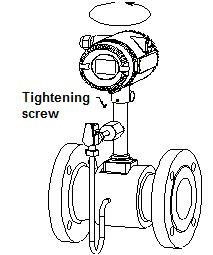
11.1 How to reverse the transmitter front and back
1) The transmitter can be reversed to front and back.
2) Before reverse the transmitter, please take out the tightening screw under the transmitter.
3) Reverse the transmitter by 180 degrees, then screw and tighten the tightening screw.
Please reference to picture 11.1
Picture 11.1: Reverse the transmitter front and back
11.2 Replace a transmitter circuit boards
1) Please make sure the power is off before replacing the transmitter.
2) Remove the front cover.
3) Loose the 4 screws on the circuit boards, than can take the boards out a little.
4) Remove all the plugs on the circuit board. Then remove the circuit board away
5) Put the new circuit board in and put the plug on
6) Tighten the 4 screws on the board, tighten the front cover
Please reference to picture 11.2
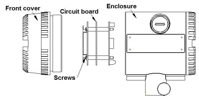
Picture 11.2: Replace the transmitter
12. Troubleshooting and repair
12.1 Safety introduction
- Please do not open the cover on the flame proof enclosure if in a explosive environment.
- When trying to wire to HART or RS485 device, please make sure that the process of wiring the device into the loop complies with the intrinsic safety requirement. Or please process the wiring in a none-explosive environment.
- Please make sure the environment the flowmeter in can meet the requirement of the certificate.
- When power is wired, please make sure the front and rear cover is closed properly.
12.2 Troubleshooting and repair
|
Symptom |
Reason |
Trouble shooting |
Repair |
|
|
No display |
Power supply failure |
Test the voltage on the power source with a universal meter |
Re-wire the power or use a new power |
|
|
Power is not wired |
Test the voltage on the power source with a universal meter |
Wire the power |
||
|
Cable if broken |
Check if there is break off point on the cable |
Check the cable and re-wire |
||
|
Wrong wiring |
Check if wiring to the correct terminal |
Re-wire |
||
|
Displayed flow rate is 0 while there are flow in the pipe |
Flow rate is lower than the meter's lower limit |
Increase the flow rate to check |
Increase the flow rate or replace a new proper flowmeter |
|
|
The flow rate of small signal cut off function is too high |
Check the small signal cut off setting |
Set the small signal cut off to a proper value |
||
|
Energy threshold value is too high |
Check if the Energy threshold value is too high in spectrum analyzing checking mode |
Set the Energy threshold value to a proper value (Please reference to Note 1 for how to set) |
|
|
|
Transmitter function failure |
Replace the transmitter with another transmitter of same type to check |
Replace the transmitter |
||
|
Sensor is damaged |
Increase the flow rate to check first, than install the transmitter to another flowmeter in same type to check. |
Replace the sensor |
||
|
Pipeline blocked or sensor jam. |
If all above possibilities are eliminated, please check the pipe line and installation. |
Re-install the flowmeter |
||
|
There is big difference between the flow reading and the process flow rate
|
No density compensation for steam measurement |
Check the density compensation devices and the setting |
Fix density compensation |
|
|
The estimated flow rate before using the meter is wrong |
Use other flowmeter to confirm the actual flow rate |
|
|
|
|
Setting incorrect |
Check the settings of meter K factor,upper and lower limit of flow rate |
Set the meter correctly |
|
|
Note 1: Enter code setting, set C49=12. Press “U-D button” to check the current energy of vortex flow signal and vibration signal. E1 is the energy of vortex flow signal, please set the energy threshold value lower than the displayed value. E.1 is the energy of vibration, please set the energy threshold value lower than the displayed value. Set above value in D017 (Energy threshold of vortex flow signal) and D018 (Energy threshold of vibration), than set C49 back to 00.
12.3 Self-diagnose function
VFM60 digital vortex flowmeter display can also indicate the self-diagnose code as below:
|
Error code |
Problem |
Repair |
|
Err-003 |
Temperature sensor disconnected |
Check Temperature sensor |
|
Err-004 |
Pressure sensor disconnected |
Check pressure sensor |
|
Err-005 |
About to over total flow |
This is a reminding message |
|
Err-006 |
Display value over limit |
The value is over the physical limit of the display |
|
Err-011 |
Superheated steam temperature is over limit |
Reduce the steam temperature |
|
Err-012 |
Superheated steam pressure is over limit |
Reduce the steam pressure |
|
Err-013 |
Button is pressed and hold for too long time |
Check the button circuit |
|
Err-014 |
Reset code setting failed |
Check EEPROM |
|
Err-015 |
Reset digital setting failed |
Check EEPROM |
|
Err-016 |
Read total flow error |
Check EEPROM |
|
Err-017 |
Temperature calibration setting is wrong |
Check the record of temperature calibration |
|
Err-018 |
pressure calibration setting is wrong |
Check the record of pressure calibration |
|
Err-020 |
Flow rate limit setting is incorrect |
Check the flow rate limit setting |
|
Err-021 |
Temperature limit setting is incorrect |
Check the temperature limit setting |
|
Err-022 |
Pressure limit setting is incorrect |
Check the pressure limit setting |
|
Err-023 |
Communication connection error |
Check the communication li |
|
Err-024 |
Setting is incorrect when using aga_nx_19 to calculate the compressibility factor |
Check if the setting for compressibility factor is correct |
|
Err-025 |
Frequency output for total flow is over limit |
Reset the total flow frequency output factor |
|
Err-026 |
3V power source failure |
Check the circuit board |
|
Err-027 |
Frequency output incorrect |
Check the range of frequency |
|
Err-028 |
The master is disconnected from the slave |
Check the cable wiring between local and remote transmitter |
13. Remark
No part of this publication may be copied or distributed, transmitted, transcribed, stored in a retrieval system, or translated into any human or computer language, in any form or by any means, electronic, mechanical, manual, or other wise, or disclosed to third parties without the express written permission of Comate Intelligent Sensor Technology. The information contained in this manual is subject to change without notice.
Appendix
Specification:
- Accuracy
|
Variables |
For gas and steam |
Liquid |
|
Flow rate (m3/h) |
±1% RD( Re ≥ 20000 ) |
±0.75% RD( Re ≥ 20000 ) |
|
±2% RD ( 10000 < Re < 20000 ) |
±2% RD (10000 < Re < 20000 ) |
|
|
Mass flow (kg/h) |
±1.5% RD( Re ≥ 20000 ) |
±1.0% RD( Re ≥ 20000 ) |
|
±2.5% RD ( 10000 < Re < 20000 ) |
±2.5% RD ( 10000 < Re < 20000 ) |
|
|
Temperature(℃) (For multi-variable version) |
±1℃ |
±1℃ |
|
Pressure (Mpa) (For multi-variable version) |
±0.75% FS |
±0.75% FS |
- Repeatability
|
Flow rate |
±0.3% |
|
Mass flow |
±0.3% |
|
Temperature |
±0.05 ℃ |
| Pressure |
±0.05% FS |
- Measurement range
|
Fluid type |
Lower limit |
Higher limit |
Condition |
|
Gas |
6m/s,DN15、DN20 |
60m/s |
T=25℃, P=101.325Kpa Air calibrated |
|
4m/s,DN25、DN32 |
|||
|
2m/s,DN40~DN300 |
|||
|
Steam |
6m/s,DN15、DN20 |
70m/s |
T=25℃, P=101.325Kpa Air calibrated |
|
4m/s,DN25、DN32 |
|||
|
2m/s,DN40~DN300 |
|||
|
Liquid |
0.3m/s |
7m/s |
T=25℃, P=101.325Kpa Water calibrated |
- Temperature range
|
Low temperature version |
−180℃~100℃ |
|
Normal temperature version |
−40℃~150℃ |
|
Medium temperature version |
−40℃~250℃ |
|
High temperature version |
−40℃~350℃ |
- Pressure range
Available pressure rating includes 1.6Mpa, 2.5Mpa, 4.0Mpa, 6.4Mpa. If the application requires a higher pressure rating , please contact us to check the possibility.
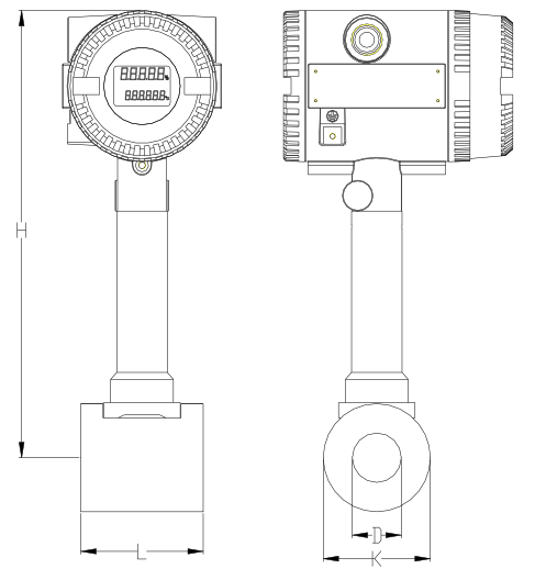
Size and dimension
Size and dimension for wafer type
 |
 |
| SVF128Wafer type 150 dgrC version | SVF128 Wafer type 250/350 dgrC version |
|
Size |
K (Pipe O/D) |
L (Pipe length) |
W (Flange screwhole distance) |
C (flange thickness) |
m (screwhole diameter) |
n (screw qty) |
H (Meter height) 150dgrC |
H (Meter height) 250dgrC |
H (Meter height) 350dgrC |
Flange O/D |
|
15 |
75 |
65 |
100 |
18 |
14 |
4 |
294 |
335 |
475 |
130 |
|
20 |
75 |
65 |
100 |
18 |
14 |
4 |
294 |
335 |
475 |
130 |
|
25 |
75 |
65 |
100 |
18 |
14 |
4 |
288.5 |
329.5 |
469.5 |
130 |
|
32 |
80 |
65 |
120 |
20 |
14 |
4 |
292.8 |
333.8 |
473.8 |
145 |
|
40 |
84 |
65 |
120 |
20 |
14 |
4 |
295.8 |
336.8 |
476.8 |
145 |
|
50 |
94 |
65 |
132 |
22 |
18 |
4 |
301 |
342 |
482 |
160 |
|
65 |
105 |
65 |
144 |
24 |
18 |
6 |
308.5 |
349.5 |
489.5 |
180 |
|
80 |
120 |
65 |
160 |
24 |
18 |
6 |
316 |
357 |
497 |
192 |
|
100 |
140 |
90 |
190 |
24 |
18 |
8 |
327 |
368 |
508 |
230 |
|
125 |
165 |
65 |
210 |
26 |
18 |
8 |
340.5 |
381.5 |
521.5 |
242 |
|
150 |
190 |
65 |
240 |
28 |
22 |
8 |
353 |
534 |
534 |
280 |
|
200 |
240 |
85 |
296 |
28 |
22 |
12 |
378 |
559 |
559 |
335 |
|
250 |
290 |
100 |
354 |
28 |
22 |
12 |
404 |
585 |
585 |
405 |
|
300 |
340 |
120 |
412 |
30 |
22 |
12 |
429 |
609 |
609 |
460 |
Remark: The flange O/D, screw holes distance, flange thickness, screw hole diameter and screw qty are for the counter flanges, unit in mm.
Counter flanges, screw and bolts, gaskets are usually along with package.
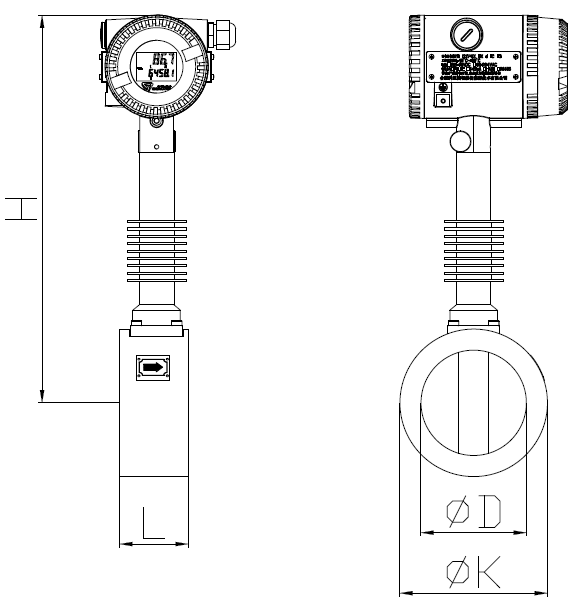
Size and dimension for flanged type
|
|
|
| SVF128 Flanged type 150 dgrC version | SVF128 Flanged type 250/350 dgrC version |


|
Size |
K (Flange O/D) |
L (Pipe length) |
W (Flange screwhole distance) |
C (flange thickness) |
m (screwhole diameter) |
n (screw qty) |
H (Meter height) 150dgrC |
H (Meter height) 250dgrC |
H (Meter height) 350dgrC |
|
15 |
90 |
180 |
60.3 |
11.6 |
15.9 |
4 |
294 |
335 |
475 |
|
20 |
100 |
180 |
69.9 |
13.2 |
15.9 |
4 |
294 |
335 |
475 |
|
25 |
110 |
180 |
79.4 |
14.7 |
15.9 |
4 |
293 |
334 |
474 |
|
32 |
117.3 |
180 |
88.9 |
16.3 |
15.9 |
4 |
300.5 |
341.5 |
481.5 |
|
40 |
127 |
180 |
98.4 |
17.9 |
15.9 |
4 |
302.5 |
343.5 |
483.5 |
|
50 |
152.4 |
180 |
120.7 |
19.5 |
19 |
4 |
307 |
348 |
488 |
|
65 |
180 |
200 |
139.7 |
22.7 |
19 |
4 |
314 |
355 |
495 |
|
80 |
190.5 |
200 |
152.4 |
24.3 |
19 |
4 |
326 |
367 |
507 |
|
100 |
230 |
200 |
190.5 |
24.3 |
19 |
8 |
336 |
377 |
517 |
|
125 |
255 |
220 |
215.9 |
24.3 |
22.2 |
8 |
345 |
386 |
526 |
|
150 |
280 |
220 |
241.3 |
25.9 |
22.2 |
8 |
360 |
541 |
541 |
|
200 |
345 |
220 |
298.5 |
29 |
22.2 |
8 |
385 |
586 |
586 |
|
250 |
405 |
250 |
362 |
30.6 |
25.4 |
12 |
412.7 |
593.7 |
593.7 |
|
300 |
485 |
300 |
431.8 |
32.2 |
25.4 |
12 |
445.4 |
626.4 |
626.4 |
Dimension of ANSI CL150 flanged version
|
Size |
K (Flange O/D) |
L (Pipe length) |
W (Flange screwhole distance) |
C (flange thickness) |
m (screwhole diameter) |
n (screw qty) |
H (Meter height) 150dgrC |
H (Meter height) 250dgrC |
H (Meter height) 350dgrC |
|
15 |
95.2 |
180 |
66.7 |
14.7 |
15.9 |
4 |
294 |
335 |
475 |
|
20 |
117.5 |
180 |
82.6 |
16.3 |
19 |
4 |
294 |
335 |
475 |
|
25 |
125 |
180 |
88.9 |
17.9 |
19 |
4 |
293 |
334 |
474 |
|
32 |
135 |
180 |
98.4 |
19.5 |
19 |
4 |
300.5 |
341.5 |
481.5 |
|
40 |
156 |
180 |
114.3 |
21.1 |
22.2 |
4 |
302.5 |
343.5 |
483.5 |
|
50 |
165.1 |
180 |
127 |
22.7 |
19 |
8 |
307 |
348 |
488 |
|
65 |
191 |
200 |
149.2 |
25.9 |
22.2 |
8 |
314 |
355 |
495 |
|
80 |
210 |
200 |
168.3 |
29 |
22.2 |
8 |
326 |
367 |
507 |
|
100 |
255 |
200 |
200 |
32.2 |
22.2 |
8 |
336 |
377 |
517 |
|
125 |
280 |
220 |
235 |
35.4 |
22.2 |
8 |
345 |
386 |
526 |
|
150 |
320 |
220 |
269.9 |
37 |
22.2 |
12 |
360 |
541 |
541 |
|
200 |
381 |
220 |
330.2 |
41.7 |
25.4 |
12 |
385 |
586 |
586 |
|
250 |
455 |
250 |
387.4 |
48.1 |
28.6 |
16 |
412.7 |
593.7 |
593.7 |
|
300 |
521 |
300 |
450.8 |
51.3 |
31.7 |
16 |
445.4 |
626.4 |
626.4 |
Dimension of ANSI CL300 flanged version
|
Size |
K (Flange O/D) |
L (Pipe length) |
W (Flange screwhole distance) |
C (flange thickness) |
m (screwhole diameter) |
n (screw qty) |
H (Meter height) 150dgrC |
H (Meter height) 250dgrC |
H (Meter height) 350dgrC |
|
15 |
95 |
180 |
65 |
14 |
14 |
4 |
294 |
335 |
475 |
|
20 |
105 |
180 |
75 |
16 |
14 |
4 |
294 |
335 |
475 |
|
25 |
115 |
180 |
85 |
16 |
14 |
4 |
293 |
334 |
474 |
|
32 |
140 |
180 |
100 |
18 |
18 |
4 |
300.5 |
341.5 |
481.5 |
|
40 |
150 |
180 |
110 |
18 |
18 |
4 |
302.5 |
343.5 |
483.5 |
|
50 |
165 |
180 |
125 |
20 |
18 |
4 |
307 |
348 |
488 |
|
65 |
185 |
200 |
145 |
20 |
18 |
8 |
314 |
355 |
495 |
|
80 |
200 |
200 |
160 |
20 |
18 |
8 |
326 |
367 |
507 |
|
100 |
220 |
200 |
180 |
22 |
18 |
8 |
336 |
377 |
517 |
|
125 |
250 |
220 |
210 |
22 |
18 |
8 |
345 |
386 |
526 |
|
150 |
285 |
220 |
240 |
24 |
22 |
8 |
360 |
541 |
541 |
|
200 |
340 |
220 |
295 |
26 |
22 |
12 |
385 |
586 |
586 |
|
250 |
405 |
250 |
355 |
29 |
26 |
12 |
412.7 |
593.7 |
593.7 |
|
300 |
460 |
300 |
410 |
32 |
26 |
12 |
445.4 |
626.4 |
626.4 |
Dimension of DIN PN16 flanged version
|
Size |
K (Flange O/D) |
L (Pipe length) |
W (Flange screwhole distance) |
C (flange thickness) |
m (screwhole diameter) |
n (screw qty) |
H (Meter height) 150dgrC |
H (Meter height) 250dgrC |
H (Meter height) 350dgrC |
|
15 |
95 |
180 |
65 |
14 |
14 |
4 |
294 |
335 |
475 |
|
20 |
105 |
180 |
75 |
16 |
14 |
4 |
294 |
335 |
475 |
|
25 |
115 |
180 |
85 |
16 |
14 |
4 |
293 |
334 |
474 |
|
32 |
140 |
180 |
100 |
18 |
18 |
4 |
300.5 |
341.5 |
481.5 |
|
40 |
150 |
180 |
110 |
18 |
18 |
4 |
302.5 |
343.5 |
483.5 |
|
50 |
165 |
180 |
125 |
20 |
18 |
4 |
307 |
348 |
488 |
|
65 |
185 |
200 |
145 |
22 |
18 |
8 |
314 |
355 |
495 |
|
80 |
200 |
200 |
160 |
24 |
18 |
8 |
326 |
367 |
507 |
|
100 |
235 |
200 |
190 |
26 |
22 |
8 |
336 |
377 |
517 |
|
125 |
270 |
220 |
220 |
28 |
26 |
8 |
345 |
386 |
526 |
|
150 |
300 |
220 |
250 |
30 |
26 |
8 |
360 |
541 |
541 |
|
200 |
360 |
220 |
310 |
32 |
26 |
12 |
385 |
586 |
586 |
|
250 |
425 |
250 |
370 |
35 |
30 |
12 |
412.7 |
593.7 |
593.7 |
|
300 |
485 |
300 |
430 |
38 |
30 |
16 |
445.4 |
626.4 |
626.4 |
Dimension of DIN PN25 flanged version
|
Size |
K (Flange O/D) |
L (Pipe length) |
W (Flange screwhole distance) |
C (flange thickness) |
m (screwhole diameter) |
n (screw qty) |
H (Meter height) 150dgrC |
H (Meter height) 250dgrC |
H (Meter height) 350dgrC |
|
15 |
95 |
180 |
65 |
14 |
14 |
4 |
294 |
335 |
475 |
|
20 |
105 |
180 |
75 |
16 |
14 |
4 |
294 |
335 |
475 |
|
25 |
115 |
180 |
85 |
16 |
14 |
4 |
293 |
334 |
474 |
|
32 |
140 |
180 |
100 |
18 |
18 |
4 |
300.5 |
341.5 |
481.5 |
|
40 |
150 |
180 |
110 |
18 |
18 |
4 |
302.5 |
343.5 |
483.5 |
|
50 |
165 |
180 |
125 |
20 |
18 |
4 |
307 |
348 |
488 |
|
65 |
185 |
200 |
145 |
22 |
18 |
8 |
314 |
355 |
495 |
|
80 |
200 |
200 |
160 |
24 |
18 |
8 |
326 |
367 |
507 |
|
100 |
235 |
200 |
190 |
26 |
22 |
8 |
336 |
377 |
517 |
|
125 |
270 |
220 |
220 |
28 |
26 |
8 |
345 |
386 |
526 |
|
150 |
300 |
220 |
250 |
30 |
26 |
8 |
360 |
541 |
541 |
|
200 |
375 |
220 |
320 |
36 |
30 |
12 |
385 |
586 |
586 |
|
250 |
450 |
250 |
385 |
42 |
33 |
12 |
412.7 |
593.7 |
593.7 |
|
300 |
515 |
300 |
450 |
52 |
33 |
16 |
445.4 |
626.4 |
626.4 |
Dimension of DIN PN40 flanged version
|
Size |
K (Flange O/D) |
L (Pipe length) |
W (Flange screwhole distance) |
C (flange thickness) |
m (screwhole diameter) |
n (screw qty) |
H (Meter height) 150dgrC |
H (Meter height) 250dgrC |
H (Meter height) 350dgrC |
|
15 |
95 |
180 |
70 |
12 |
15 |
4 |
294 |
335 |
475 |
|
20 |
100 |
180 |
75 |
14 |
15 |
4 |
294 |
335 |
475 |
|
25 |
125 |
180 |
90 |
14 |
19 |
4 |
293 |
334 |
474 |
|
32 |
135 |
180 |
100 |
16 |
19 |
4 |
300.5 |
341.5 |
481.5 |
|
40 |
140 |
180 |
105 |
16 |
19 |
4 |
302.5 |
343.5 |
483.5 |
|
50 |
155 |
180 |
120 |
16 |
19 |
4 |
307 |
348 |
488 |
|
65 |
175 |
200 |
140 |
18 |
19 |
4 |
314 |
355 |
495 |
|
80 |
185 |
200 |
150 |
18 |
19 |
8 |
326 |
367 |
507 |
|
100 |
210 |
200 |
175 |
18 |
19 |
8 |
336 |
377 |
517 |
|
125 |
250 |
220 |
210 |
20 |
23 |
8 |
345 |
386 |
526 |
|
150 |
280 |
220 |
240 |
22 |
23 |
8 |
360 |
541 |
541 |
|
200 |
330 |
220 |
290 |
22 |
23 |
12 |
385 |
586 |
586 |
|
250 |
400 |
250 |
355 |
24 |
25 |
12 |
412.7 |
593.7 |
593.7 |
|
300 |
445 |
300 |
400 |
24 |
25 |
16 |
445.4 |
626.4 |
626.4 |
Dimension of JIS 10K flanged version
|
Size |
K (Flange O/D) |
L (Pipe length) |
W (Flange screwhole distance) |
C (flange thickness) |
m (screwhole diameter) |
n (screw qty) |
H (Meter height) 150dgrC |
H (Meter height) 250dgrC |
H (Meter height) 350dgrC |
|
15 |
95 |
180 |
70 |
14 |
15 |
4 |
294 |
335 |
475 |
|
20 |
100 |
180 |
75 |
16 |
15 |
4 |
294 |
335 |
475 |
|
25 |
125 |
180 |
90 |
16 |
19 |
4 |
293 |
334 |
474 |
|
32 |
135 |
180 |
100 |
18 |
19 |
4 |
300.5 |
341.5 |
481.5 |
|
40 |
140 |
180 |
105 |
18 |
19 |
4 |
302.5 |
343.5 |
483.5 |
|
50 |
155 |
180 |
120 |
18 |
19 |
8 |
307 |
348 |
488 |
|
65 |
175 |
200 |
140 |
20 |
19 |
8 |
314 |
355 |
495 |
|
80 |
200 |
200 |
160 |
22 |
23 |
8 |
326 |
367 |
507 |
|
100 |
225 |
200 |
185 |
24 |
23 |
8 |
336 |
377 |
517 |
|
125 |
270 |
220 |
225 |
26 |
25 |
8 |
345 |
386 |
526 |
|
150 |
305 |
220 |
260 |
28 |
25 |
12 |
360 |
541 |
541 |
|
200 |
350 |
220 |
305 |
30 |
25 |
12 |
385 |
586 |
586 |
|
250 |
430 |
250 |
380 |
34 |
27 |
12 |
412.7 |
593.7 |
593.7 |
|
300 |
480 |
300 |
430 |
36 |
27 |
16 |
445.4 |
626.4 |
626.4 |
Dimension of JIS 20K flanged version
Remark: Flanged version do not contains screws and bolts in the package unless customer need to purchase from us. We also have flanged type in other standard and pressure rating. Please check with us if you require flanged version other than what we provided
Size and dimension for multi-variable wafer type
|
|
|
|
SVF128 Wafer type 150 dgrC version |
SVF128 Wafer type 250/350 dgrC version |
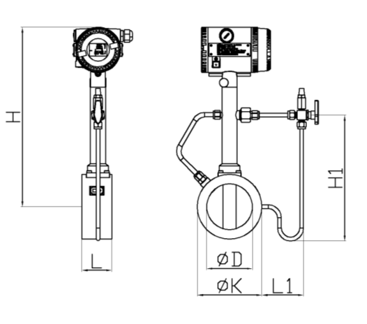
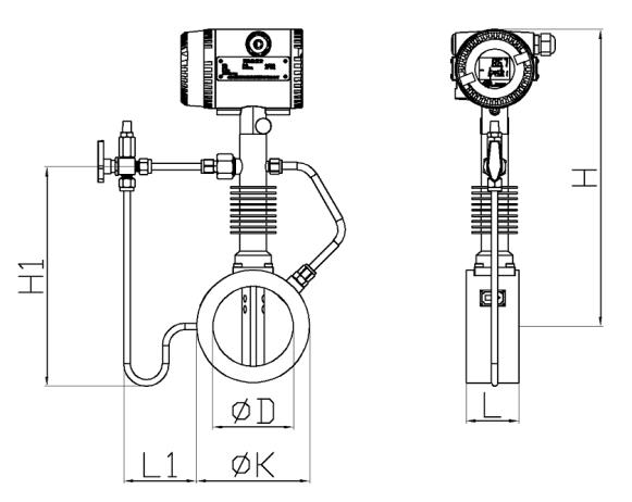
|
Size |
K (Flange O/D) |
L (Pipe length) |
W (Flange screwhole distance) |
C (flange thickness) |
m (screwhole diameter) |
n (screw qty) |
L1 (Condensation pipe length) |
|
15 |
75 | 65 |
100 |
18 |
14 |
4 |
86 |
|
20 |
75 | 65 |
100 |
18 |
14 |
4 |
83.5 |
|
25 |
75 | 65 |
100 |
18 |
14 |
4 |
86 |
|
32 |
80 | 65 |
120 |
20 |
14 |
4 |
87 |
|
40 |
84 | 65 |
120 |
20 |
14 |
4 |
89 |
|
50 |
94 | 65 |
132 |
22 |
18 |
4 |
89 |
|
65 |
105 | 65 |
144 |
24 |
18 |
6 |
91 |
|
80 |
120 | 65 |
160 |
24 |
18 |
6 |
111 |
|
100 |
140 | 90 |
190 |
24 |
18 |
8 |
90 |
|
125 |
165 | 65 |
210 |
26 |
18 |
8 |
86 |
|
150 |
190 | 65 |
240 |
28 |
22 |
8 |
86 |
|
200 |
240 | 85 |
296 |
28 |
22 |
12 |
106 |
|
250 |
290 | 100 |
354 |
28 |
22 |
12 |
106 |
|
300 |
340 | 120 |
412 |
30 |
22 |
12 |
106 |
|
H (Meter height) 150dgrC |
H1 (Condensation pipe height 150 dgrC) |
H (Meter height) 250dgrC |
H1 (Condensation pipe height 250 dgrC) |
H (Meter height) 350dgrC |
H1 (Condensation pipe height 350 dgrC) |
|
294 |
183 |
335 |
234 |
475 |
374 |
|
294 |
183 |
335 |
234 |
475 |
374 |
|
228.5 |
177.5 |
329.5 |
228.5 |
469.5 |
368.5 |
|
292.8 |
181.8 |
333.8 |
232.8 |
473.8 |
372.8 |
|
295.8 |
184.8 |
336.8 |
235.8 |
476.8 |
375.8 |
|
310 |
190 |
342 |
241 |
482 |
381 |
|
308.5 |
197.5 |
349.5 |
248.5 |
489.5 |
388.5 |
|
316 |
247.5 |
357 |
298.5 |
497 |
438.5 |
|
327 |
221 |
368 |
272 |
508 |
412 |
|
340.5 |
239.5 |
381.5 |
290.5 |
521.5 |
430.5 |
|
353 |
267 |
534 |
458 |
534 |
458 |
|
378 |
317 |
559 |
508 |
559 |
508 |
|
404 |
368 |
585 |
559 |
585 |
559 |
|
429 |
418 |
609 |
609 |
609 |
609 |
Size and dimension for multi-variable flanged type
|
|
|
|
SVF128 Flanged type 150 dgrC version |
SVF128 Flanged type 250/350 dgrC version |


|
Size |
K (Flange O/D) |
L (Pipe length) |
W (Flange screwhole distance) |
C (flange thickness) |
m (screwhole diameter) |
n (screw qty) |
L1 (Condensation pipe length) |
|
15 |
95 |
180 |
65 |
14 |
14 |
4 |
76 |
|
20 |
105 |
180 |
75 |
16 |
14 |
4 |
68.5 |
|
25 |
115 |
180 |
85 |
16 |
14 |
4 |
66 |
|
32 |
140 |
180 |
100 |
18 |
18 |
4 |
57 |
|
40 |
150 |
180 |
110 |
18 |
18 |
4 |
56 |
|
50 |
165 |
180 |
125 |
20 |
18 |
4 |
53.5 |
|
65 |
185 |
200 |
145 |
20 |
18 |
8 |
51 |
|
80 |
200 |
200 |
160 |
20 |
18 |
8 |
51 |
|
100 |
220 |
200 |
180 |
22 |
18 |
8 |
50 |
|
125 |
250 |
220 |
210 |
22 |
18 |
8 |
43.5 |
|
150 |
285 |
220 |
240 |
24 |
22 |
8 |
38.5 |
|
200 |
340 |
220 |
295 |
26 |
22 |
12 |
56 |
|
250 |
405 |
250 |
355 |
29 |
26 |
12 |
48.5 |
|
300 |
460 |
300 |
410 |
32 |
26 |
12 |
46 |
|
H (Meter height) 150dgrC |
H1 (Condensation pipe height 150 dgrC) |
H (Meter height) 250dgrC |
H1 (Condensation pipe height 250 dgrC) |
H (Meter height) 350dgrC |
H1 (Condensation pipe height 350 dgrC) |
|
294 |
183 |
335 |
234 |
475 |
374 |
|
294 |
183 |
335 |
234 |
475 |
374 |
|
293 |
186 |
334 |
237 |
474 |
377 |
|
300.5 |
193.5 |
341.5 |
244.5 |
481.5 |
384.5 |
|
302.5 |
195.5 |
343.5 |
246.5 |
483.5 |
386.5 |
|
307 |
200 |
348 |
251 |
488 |
391 |
|
314 |
207 |
355 |
258 |
495 |
398 |
|
326 |
219 |
367 |
270 |
507 |
410 |
|
336 |
234 |
377 |
285 |
517 |
425 |
|
345 |
248 |
386 |
299 |
526 |
439 |
|
360 |
278 |
541 |
469 |
541 |
469 |
|
385 |
328 |
566 |
519 |
566 |
519 |
|
412.7 |
380.7 |
593.7 |
571.7 |
593.7 |
571.7 |
|
445.4 |
438.4 |
626.4 |
629.4 |
626.4 |
629.4 |
Dimension of DIN PN16 flanged version
|
Size |
K (Flange O/D) |
L (Pipe length) |
W (Flange screwhole distance) |
C (flange thickness) |
m (screwhole diameter) |
n (screw qty) |
L1 (Condensation pipe length) |
|
15 |
95 |
180 |
65 |
14 |
14 |
4 |
76 |
|
20 |
105 |
180 |
75 |
16 |
14 |
4 |
68.5 |
|
25 |
115 |
180 |
85 |
16 |
14 |
4 |
66 |
|
32 |
140 |
180 |
100 |
18 |
18 |
4 |
57 |
|
40 |
150 |
180 |
110 |
18 |
18 |
4 |
56 |
|
50 |
165 |
180 |
125 |
20 |
18 |
4 |
53.5 |
|
65 |
185 |
200 |
145 |
22 |
18 |
8 |
51 |
|
80 |
200 |
200 |
160 |
24 |
18 |
8 |
51 |
|
100 |
235 |
200 |
190 |
26 |
22 |
8 |
32.5 |
|
125 |
270 |
220 |
220 |
28 |
26 |
8 |
33.5 |
|
150 |
300 |
220 |
250 |
30 |
26 |
8 |
31 |
|
200 |
360 |
220 |
310 |
32 |
26 |
12 |
46 |
|
250 |
425 |
250 |
370 |
35 |
30 |
12 |
38.5 |
|
300 |
485 |
300 |
430 |
38 |
30 |
16 |
33.5 |
|
H (Meter height) 150dgrC |
H1 (Condensation pipe height 150 dgrC) |
H (Meter height) 250dgrC |
H1 (Condensation pipe height 250 dgrC) |
H (Meter height) 350dgrC |
H1 (Condensation pipe height 350 dgrC) |
|
294 |
183 |
335 |
234 |
475 |
374 |
|
294 |
183 |
335 |
234 |
475 |
374 |
|
293 |
186 |
334 |
237 |
474 |
377 |
|
300.5 |
193.5 |
341.5 |
244.5 |
481.5 |
384.5 |
|
302.5 |
195.5 |
343.5 |
246.5 |
483.5 |
386.5 |
|
307 |
200 |
348 |
251 |
488 |
391 |
|
314 |
207 |
355 |
258 |
495 |
398 |
|
326 |
219 |
367 |
270 |
507 |
410 |
|
336 |
234 |
377 |
285 |
517 |
425 |
|
345 |
248 |
386 |
299 |
526 |
439 |
|
360 |
278 |
541 |
469 |
541 |
469 |
|
385 |
328 |
566 |
519 |
566 |
519 |
|
412.7 |
380.7 |
593.7 |
571.7 |
593.7 |
571.7 |
|
445.4 |
438.4 |
626.4 |
629.4 |
626.4 |
629.4 |
Dimension of DIN PN25 flanged version
|
Size |
K (Flange O/D) |
L (Pipe length) |
W (Flange screwhole distance) |
C (flange thickness) |
m (screwhole diameter) |
n (screw qty) |
L1 (Condensation pipe length) |
|
15 |
95 |
180 |
65 |
14 |
14 |
4 |
76 |
|
20 |
105 |
180 |
75 |
16 |
14 |
4 |
68.5 |
|
25 |
115 |
180 |
85 |
16 |
14 |
4 |
66 |
|
32 |
140 |
180 |
100 |
18 |
18 |
4 |
57 |
|
40 |
150 |
180 |
110 |
18 |
18 |
4 |
56 |
|
50 |
165 |
180 |
125 |
20 |
18 |
4 |
53.5 |
|
65 |
185 |
200 |
145 |
22 |
18 |
8 |
51 |
|
80 |
200 |
200 |
160 |
24 |
18 |
8 |
51 |
|
100 |
235 |
200 |
190 |
26 |
22 |
8 |
32.5 |
|
125 |
270 |
220 |
220 |
28 |
26 |
8 |
33.5 |
|
150 |
300 |
220 |
250 |
30 |
26 |
8 |
31 |
|
200 |
375 |
220 |
320 |
36 |
30 |
12 |
39.5 |
|
250 |
450 |
250 |
385 |
42 |
33 |
12 |
36 |
|
300 |
515 |
300 |
430 |
52 |
33 |
16 |
18.5 |
|
H (Meter height) 150dgrC |
H1 (Condensation pipe height 150 dgrC) |
H (Meter height) 250dgrC |
H1 (Condensation pipe height 250 dgrC) |
H (Meter height) 350dgrC |
H1 (Condensation pipe height 350 dgrC) |
|
294 |
183 |
335 |
234 |
475 |
374 |
|
294 |
183 |
335 |
234 |
475 |
374 |
|
293 |
186 |
334 |
237 |
474 |
377 |
|
300.5 |
193.5 |
341.5 |
244.5 |
481.5 |
384.5 |
|
302.5 |
195.5 |
343.5 |
246.5 |
483.5 |
386.5 |
|
307 |
200 |
348 |
251 |
488 |
391 |
|
314 |
207 |
355 |
258 |
495 |
398 |
|
326 |
219 |
367 |
270 |
507 |
410 |
|
336 |
234 |
377 |
285 |
517 |
425 |
|
345 |
248 |
386 |
299 |
526 |
439 |
|
360 |
278 |
541 |
469 |
541 |
469 |
|
385 |
328 |
566 |
519 |
566 |
519 |
|
412.7 |
380.7 |
593.7 |
571.7 |
593.7 |
571.7 |
|
445.4 |
438.4 |
626.4 |
629.4 |
626.4 |
629.4 |
Dimension of DIN PN40 flanged version
|
Size |
K (Flange O/D) |
L (Pipe length) |
W (Flange screwhole distance) |
C (flange thickness) |
m (screwhole diameter) |
n (screw qty) |
L1 (Condensation pipe length) |
|
15 |
90 |
180 |
60.3 |
11.6 |
15.9 |
4 |
73.5 |
|
20 |
100 |
180 |
69.9 |
13.2 |
15.9 |
4 |
66 |
|
25 |
110 |
180 |
79.4 |
14.7 |
15.9 |
4 |
63.5 |
|
32 |
117.3 |
180 |
88.9 |
16.3 |
15.9 |
4 |
68 |
|
40 |
127 |
180 |
98.4 |
17.9 |
15.9 |
4 |
67.5 |
|
50 |
152.4 |
180 |
120.7 |
19.5 |
19 |
4 |
61 |
|
65 |
180 |
200 |
139.7 |
22.7 |
19 |
4 |
48.5 |
|
80 |
190.5 |
200 |
152.4 |
24.3 |
19 |
4 |
46 |
|
100 |
230 |
200 |
190.5 |
24.3 |
19 |
8 |
40 |
|
125 |
255 |
220 |
215.9 |
24.3 |
22.2 |
8 |
41 |
|
150 |
280 |
220 |
241.3 |
25.9 |
22.2 |
8 |
36 |
|
200 |
345 |
220 |
298.5 |
29 |
22.2 |
8 |
53.5 |
|
250 |
406.4 |
250 |
362 |
30.6 |
25.4 |
12 |
48 |
|
300 |
485 |
300 |
431.8 |
32.2 |
25.4 |
12 |
39.5 |
|
H (Meter height) 150dgrC |
H1 (Condensation pipe height 150 dgrC) |
H (Meter height) 250dgrC |
H1 (Condensation pipe height 250 dgrC) |
H (Meter height) 350dgrC |
H1 (Condensation pipe height 350 dgrC) |
|
294 |
183 |
335 |
234 |
475 |
374 |
|
294 |
183 |
335 |
234 |
475 |
374 |
|
293 |
186 |
334 |
237 |
474 |
377 |
|
300.5 |
193.5 |
341.5 |
244.5 |
481.5 |
384.5 |
|
302.5 |
195.5 |
343.5 |
246.5 |
483.5 |
386.5 |
|
307 |
200 |
348 |
251 |
488 |
391 |
|
314 |
207 |
355 |
258 |
495 |
398 |
|
326 |
219 |
367 |
270 |
507 |
410 |
|
336 |
234 |
377 |
285 |
517 |
425 |
|
345 |
248 |
386 |
299 |
526 |
439 |
|
360 |
278 |
541 |
469 |
541 |
469 |
|
385 |
328 |
566 |
519 |
566 |
519 |
|
412.7 |
380.7 |
593.7 |
571.7 |
593.7 |
571.7 |
|
445.4 |
438.4 |
626.4 |
629.4 |
626.4 |
629.4 |
Dimension of ANSI CL150 flanged version
|
Size |
K (Flange O/D) |
L (Pipe length) |
W (Flange screwhole distance) |
C (flange thickness) |
m (screwhole diameter) |
n (screw qty) |
L1 (Condensation pipe length) |
|
15 |
95.2 |
180 |
66.7 |
14.7 |
15.9 |
4 |
71 |
|
20 |
117.5 |
180 |
82.6 |
16.3 |
19 |
4 |
57.2 |
|
25 |
125 |
180 |
88.9 |
17.9 |
19 |
4 |
51 |
|
32 |
135 |
180 |
98.4 |
19.5 |
19 |
4 |
59 |
|
40 |
156 |
180 |
114.3 |
21.1 |
22.2 |
4 |
53 |
|
50 |
165.1 |
180 |
127 |
22.7 |
19 |
8 |
54.7 |
|
65 |
191 |
200 |
149.2 |
25.9 |
22.2 |
8 |
43 |
|
80 |
210 |
200 |
168.3 |
29 |
22.2 |
8 |
36.3 |
|
100 |
255 |
200 |
200 |
32.2 |
22.2 |
8 |
28.5 |
|
125 |
280 |
220 |
235 |
35.4 |
22.2 |
8 |
28.5 |
|
150 |
320 |
220 |
269.9 |
37 |
22.2 |
12 |
16 |
|
200 |
381 |
222 |
330.2 |
41.7 |
25.4 |
12 |
35.5 |
|
250 |
445 |
250 |
387.3 |
48.1 |
28.6 |
16 |
28.7 |
|
300 |
521 |
300 |
450.8 |
51.3 |
31.7 |
16 |
21.5 |
|
H (Meter height) 150dgrC |
H1 (Condensation pipe height 150 dgrC) |
H (Meter height) 250dgrC |
H1 (Condensation pipe height 250 dgrC) |
H (Meter height) 350dgrC |
H1 (Condensation pipe height 350 dgrC) |
|
294 |
183 |
335 |
234 |
475 |
374 |
|
294 |
183 |
335 |
234 |
475 |
374 |
|
293 |
186 |
334 |
237 |
474 |
377 |
|
300.5 |
193.5 |
341.5 |
244.5 |
481.5 |
384.5 |
|
302.5 |
195.5 |
343.5 |
246.5 |
483.5 |
386.5 |
|
307 |
200 |
348 |
251 |
488 |
391 |
|
314 |
207 |
355 |
258 |
495 |
398 |
|
326 |
219 |
367 |
270 |
507 |
410 |
|
336 |
234 |
377 |
285 |
517 |
425 |
|
345 |
248 |
386 |
299 |
526 |
439 |
|
360 |
278 |
541 |
469 |
541 |
469 |
|
385 |
328 |
566 |
519 |
566 |
519 |
|
412.7 |
380.7 |
593.7 |
571.7 |
593.7 |
571.7 |
|
445.4 |
438.4 |
626.4 |
629.4 |
626.4 |
629.4 |
Dimension of ANSI CL300 flanged version
|
Size |
K (Flange O/D) |
L (Pipe length) |
W (Flange screwhole distance) |
C (flange thickness) |
m (screwhole diameter) |
n (screw qty) |
L1 (Condensation pipe length) |
|
15 |
95 |
180 |
70 |
12 |
15 |
4 |
76 |
|
20 |
100 |
180 |
75 |
14 |
15 |
4 |
66 |
|
25 |
125 |
180 |
90 |
14 |
19 |
4 |
61 |
|
32 |
135 |
180 |
100 |
16 |
19 |
4 |
54.5 |
|
40 |
140 |
180 |
105 |
16 |
19 |
4 |
56 |
|
50 |
155 |
180 |
120 |
16 |
19 |
4 |
56 |
|
65 |
175 |
200 |
140 |
18 |
19 |
4 |
56 |
|
80 |
185 |
200 |
150 |
18 |
19 |
8 |
42.5 |
|
100 |
210 |
200 |
175 |
18 |
19 |
8 |
55 |
|
125 |
250 |
220 |
210 |
20 |
23 |
8 |
43.5 |
|
150 |
280 |
220 |
240 |
22 |
23 |
8 |
41 |
|
200 |
330 |
220 |
290 |
22 |
23 |
12 |
61 |
|
250 |
400 |
250 |
355 |
24 |
25 |
12 |
51 |
|
300 |
445 |
300 |
400 |
24 |
25 |
16 |
53.5 |
|
H (Meter height) 150dgrC |
H1 (Condensation pipe height 150 dgrC) |
H (Meter height) 250dgrC |
H1 (Condensation pipe height 250 dgrC) |
H (Meter height) 350dgrC |
H1 (Condensation pipe height 350 dgrC) |
|
294 |
183 |
335 |
234 |
475 |
374 |
|
294 |
183 |
335 |
234 |
475 |
374 |
|
293 |
186 |
334 |
237 |
474 |
377 |
|
300.5 |
193.5 |
341.5 |
244.5 |
481.5 |
384.5 |
|
302.5 |
195.5 |
343.5 |
246.5 |
483.5 |
386.5 |
|
307 |
200 |
348 |
251 |
488 |
391 |
|
314 |
207 |
355 |
258 |
495 |
398 |
|
326 |
219 |
367 |
270 |
507 |
410 |
|
336 |
234 |
377 |
285 |
517 |
425 |
|
345 |
248 |
386 |
299 |
526 |
439 |
|
360 |
278 |
541 |
469 |
541 |
469 |
|
385 |
328 |
566 |
519 |
566 |
519 |
|
412.7 |
380.7 |
593.7 |
571.7 |
593.7 |
571.7 |
|
445.4 |
438.4 |
626.4 |
629.4 |
626.4 |
629.4 |
Dimension of JIS 10K flanged version
|
Size |
K (Flange O/D) |
L (Pipe length) |
W (Flange screwhole distance) |
C (flange thickness) |
m (screwhole diameter) |
n (screw qty) |
L1 (Condensation pipe length) |
|
15 |
95 |
180 |
70 |
14 |
15 |
4 |
76 |
|
20 |
100 |
180 |
75 |
16 |
15 |
4 |
66 |
|
25 |
125 |
180 |
90 |
16 |
19 |
4 |
61 |
|
32 |
135 |
180 |
100 |
18 |
19 |
4 |
54.5 |
|
40 |
140 |
180 |
105 |
18 |
19 |
4 |
56 |
|
50 |
155 |
180 |
120 |
18 |
19 |
8 |
56 |
|
65 |
175 |
200 |
140 |
20 |
19 |
8 |
56 |
|
80 |
200 |
200 |
160 |
22 |
23 |
8 |
35 |
|
100 |
225 |
200 |
185 |
24 |
23 |
8 |
47.5 |
|
125 |
270 |
220 |
225 |
26 |
25 |
8 |
33.5 |
|
150 |
305 |
220 |
260 |
28 |
25 |
12 |
28.5 |
|
200 |
350 |
220 |
305 |
30 |
25 |
12 |
51 |
|
250 |
430 |
250 |
380 |
34 |
27 |
12 |
36 |
|
300 |
480 |
300 |
430 |
36 |
27 |
16 |
36 |
|
H (Meter height) 150dgrC |
H1 (Condensation pipe height 150 dgrC) |
H (Meter height) 250dgrC |
H1 (Condensation pipe height 250 dgrC) |
H (Meter height) 350dgrC |
H1 (Condensation pipe height 350 dgrC) |
|
294 |
183 |
335 |
234 |
475 |
374 |
|
294 |
183 |
335 |
234 |
475 |
374 |
|
293 |
186 |
334 |
237 |
474 |
377 |
|
300.5 |
193.5 |
341.5 |
244.5 |
481.5 |
384.5 |
|
302.5 |
195.5 |
343.5 |
246.5 |
483.5 |
386.5 |
|
307 |
200 |
348 |
251 |
488 |
391 |
|
314 |
207 |
355 |
258 |
495 |
398 |
|
326 |
219 |
367 |
270 |
507 |
410 |
|
336 |
234 |
377 |
285 |
517 |
425 |
|
345 |
248 |
386 |
299 |
526 |
439 |
|
360 |
278 |
541 |
469 |
541 |
469 |
|
385 |
328 |
566 |
519 |
566 |
519 |
|
412.7 |
380.7 |
593.7 |
571.7 |
593.7 |
571.7 |
|
445.4 |
438.4 |
626.4 |
629.4 |
626.4 |
629.4 |
Dimension of JIS 20K flanged version
Size and dimension for insertion type
|
|
Size |
H (High) |
|
300 |
580 |
|
|
350 |
605 |
|
|
400 |
630 |
|
|
500 |
680 |
|
|
600 |
730 |
|
|
700 |
780 |
|
|
800 |
830 |
|
|
900 |
880 |
|
|
1000 |
930 |
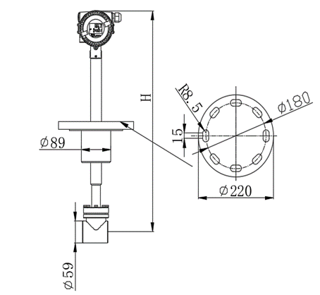
Size and dimension for remote converter
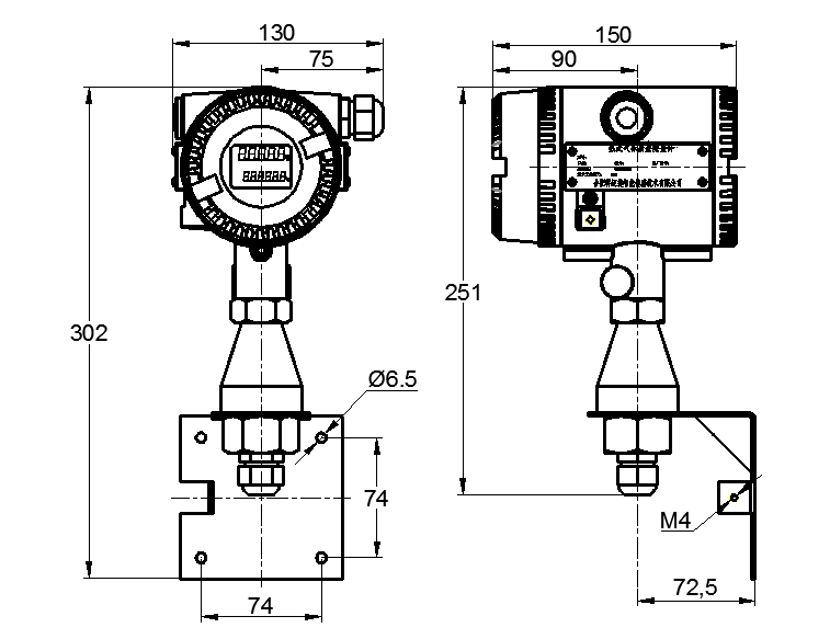
14. Support Contact
|
Manufacturer
Daviteq Technologies Inc Email: info@daviteq.com | www.daviteq.com
|
Distributor in Australia and New Zealand
Templogger Pty Ltd Tel: 1800 LOGGER Email: contact@templogger.net |

No Comments