Vizuo Software On Web
| MN-VIZUO-EN |
Mar-2020 |

1. Functions Change Log
| Release Date | Version | Functions Change |
|
Mar-2020 |
1.0
|
Update Menu Administration |
2. Introduction
Vizuo is a web-based software application to remotely configure device, parameter, alarm and event. In addition, Vizuo displays current values, historical values of parameters as well as events, alarms. Values of parameter are stored on database of GLOBIOTS server. Below figure describes the system which uses Vizuo application software: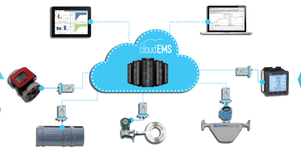
3. User Information and Actions
3.1 Sign in
- Open a web browser (Google Chrome/Firefox/Internet Explorer…).
- Enter address in URL: http://vizuo.globiots.com/
- Sign-in page displays as follow:
• Enter username and password
• Click “Sign in” button.
- After successful sign-in, Dashboard screen will appear: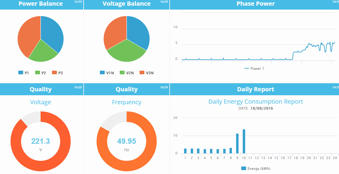
- For user first time sign-in or reset password, user’s password must be changed after successful sign-in
- Screen of change password:
- After changing password successfully, Dashboard screen will display.
3.2 User Profile
- To view User Profile, click user name on right corner screen → select My Profile: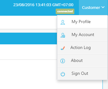
- My Profile page displays as follow:
• Basic Information tab:
o Name: Name of user
o Verify: Click to send confirmation to email address or Contact Number
3.3 Verify email
In My Profile, tab Basic Information, click Verify in row Email. After clicking, verification email will be sent to the email. User logs in email, open verification email and click verification button in email to verify email. If verification is successful, button
Verify in row email should disappear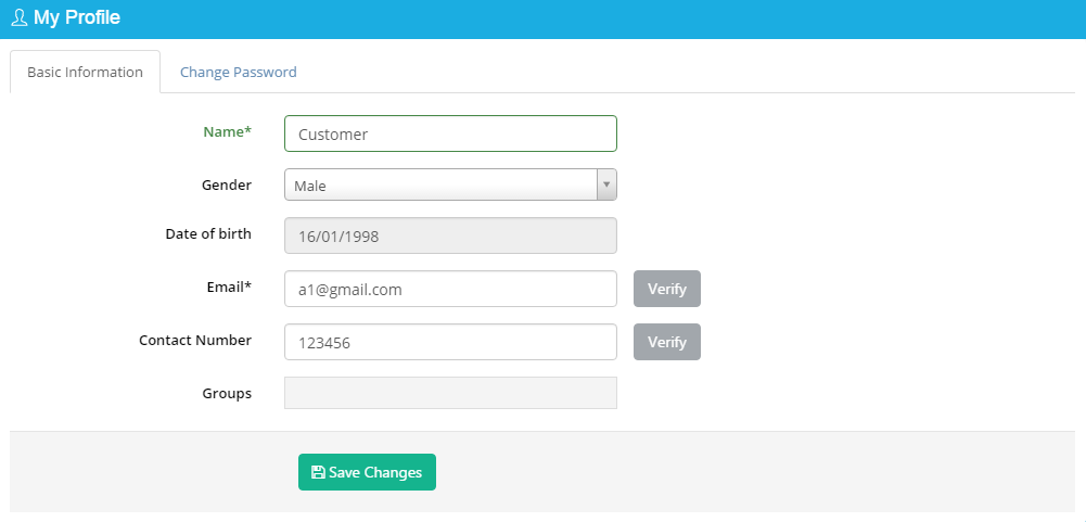
3.4 Verify Contact Number
In My Profile, tab Basic information, click Verify in row Contact Number. After clicking, authorization code will be sent SMS to user contact number and user enter this code to dialog to complete verification. If verification is successful, button Verify in row Contact Number should disappear
3.5 Account Information
To view Information of Account, click user name on right corner → select My Account. “My Account” page displays as follow: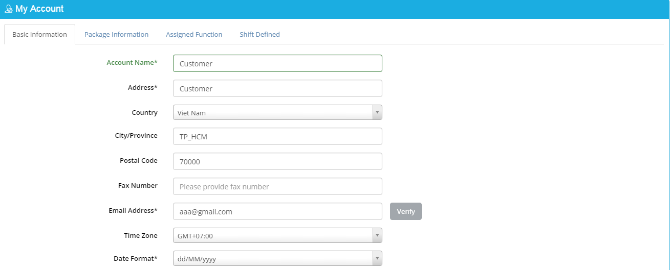
3.6 Action Log
To view history of user action, click user name on right corner → select Action Log. “The list of Action Log” will displays as follow: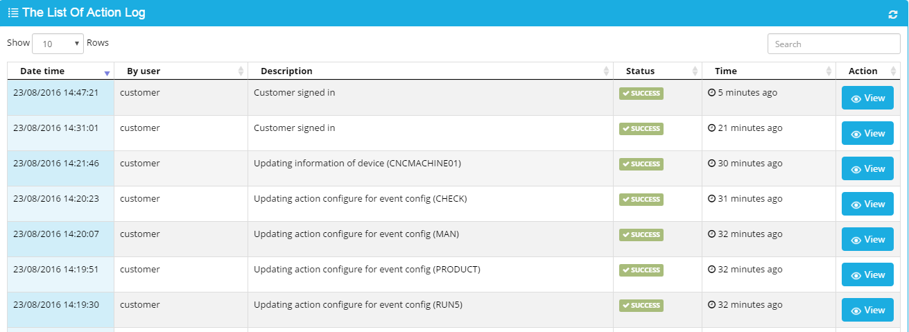
3.7 About
To view basic information of Vizuo application software, click user name on right corner → select About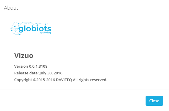
3.8 Change Password
To Change Password, you click user name on right corner → select My Profile → Change Password tab, enter old password and new password, then click button Save Changes, and OK to confirm password change
3.9 Sign out
In Home page, select Username at top right corner→ click Sign Out
4. Configure Node
4.1 Node Definition
In Organization Chart Panel, Node is used to create Organization Chart. Node name should be geographical area, type of energy or responsible person. A Node includes one or more sub-Node and Device
4.2 Organization Chart
To close or open “Organization Chart” panel, you can click  on left corner of screen Organization Chart page includes all Node and Device in system:
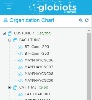
• Node name
• Number using device of account/Max number device of account
Right click on Node name, menu of Node displays: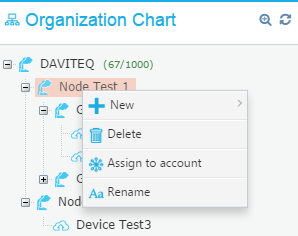
• New: Create new Node, Device
• Delete: Delete Node
• Assign to account: Assign Node and sub-Node to account
• Rename: Change name of Node
4.3 Create a Node
To Create a sub-Node:
(1) Select Node
(2) Right click and select “New”
(3) Click “Node” to create new Node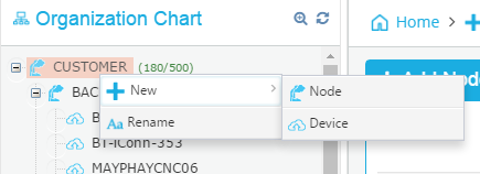
(4) Enter sub-Node name and click button Save, then click button OK to confirm
4.4 Rename Node
To change name of Node, right click on Node name → select Rename Or double click on Node. Enter new name and click button “Save Changes” to complete
4.5 Delete node
In Organization Chart, select Node that you want to delete, right click Node name → select “Delete”, click button OK. Enter Username and Password of Account to confirm
- Do not delete a Node that is assigned to account
- Do not delete a Node that includes sub-node
4.6 Assign Node to account
- In Organization Chart panel , select Node to assign to account, right click Node name → select “Assign to account” : A list account displays: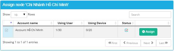
- Click “Assign” button to assign Node to account Or Click “Unassign” to un-assign Node from account.
5. Configure Device
5.1 Device Definition
Device is smart gateway (iConnector). Device stores data from meter/sensor temporarily and then transmits data to server.
5.2 Create a new Memmap
Customer has to have a memory map excel file provided by manufacturer
To create a new Memmap:
(1) Select Memmap Configuration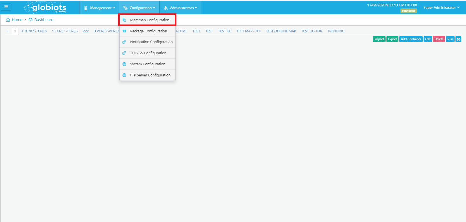 (2) Click "Add Memmap" to create a new Memmap
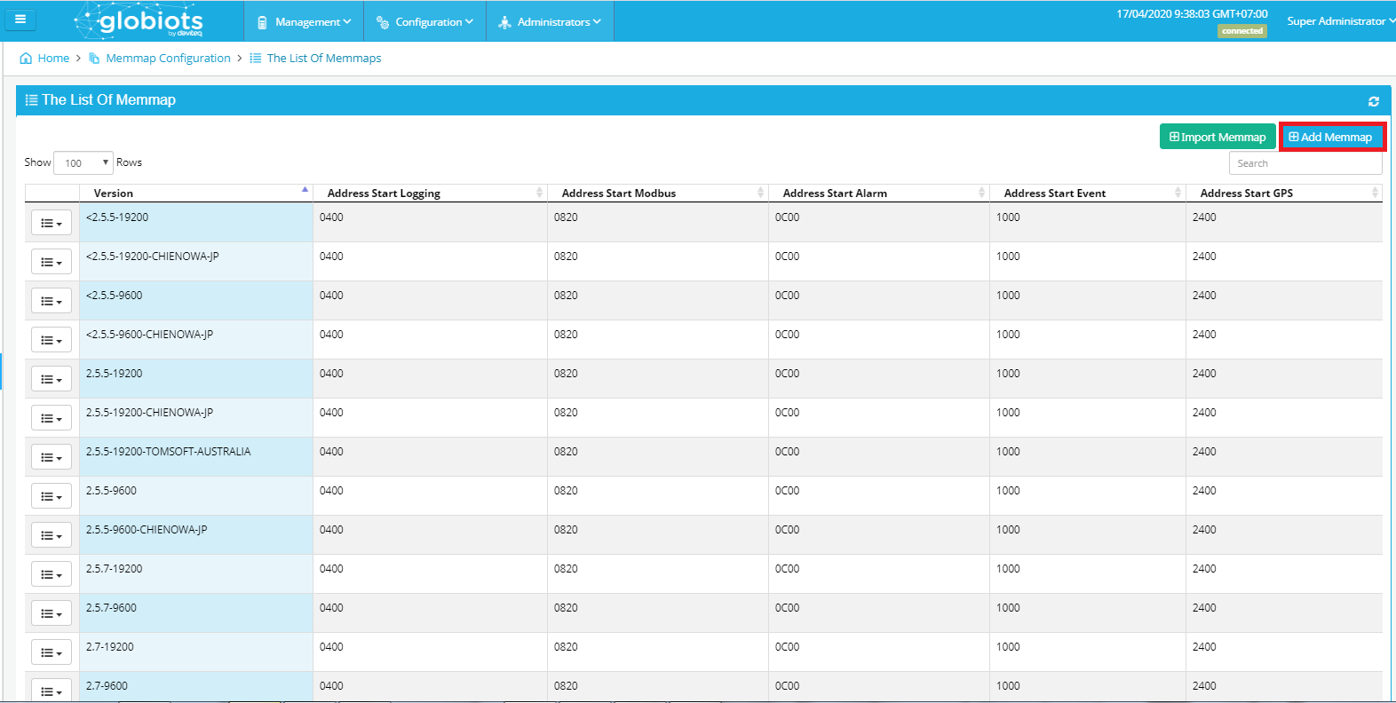
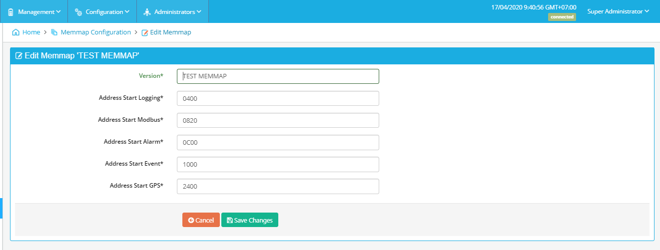 • Version: version of MemMap
• Address Start Logging: Start address of the Logging configuration area, sync from server to iConnector
• Address Start Modbus: Start address of the Modbus configuration area, sync from server to iConnector
• Address Start Alarm: Start address of the Alarm configuration area, sync from server to iConnector
• Address Start Event: Start address of the Event configuration area, sync from server to iConnector
• Address Start GPS: Start address of the GPS configuration area, sync from server to iConnector
Click "Save changes"
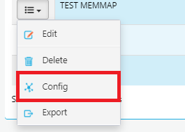
(3) Select Memmap and click “Config"
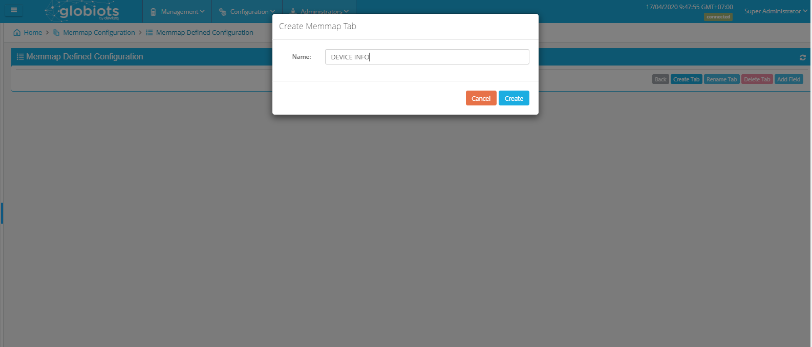
(4) Click "Create Tab" and fill the name of tab
(5) Click “Add field" and fill infomation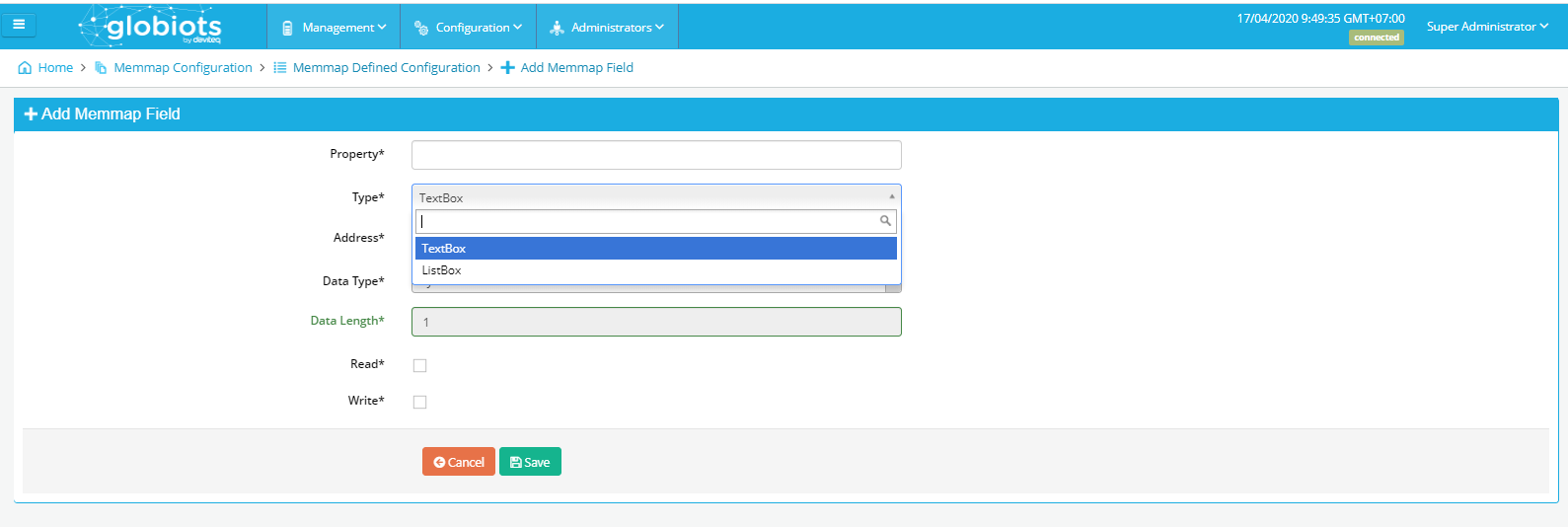
• Property: description of field
• Type: have two type: TexBox and ListBox
o TexBox: Write value directly to Address
o ListBox: Mapping value then write to Address
Example: Mapping 0=4800, 1=9600, 2=19200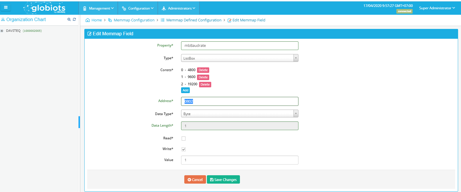
• Address: Address from Memmap file
• Data Type: Data Type from Memmap file
• Data Length: Data Length from Memmap file
• Read: tick to permit read
• Write: tick to permit write
• Value: Value write to Address
Click "Save changes"
Example: Memmap 3.6-9600
(1) DEVICE INFO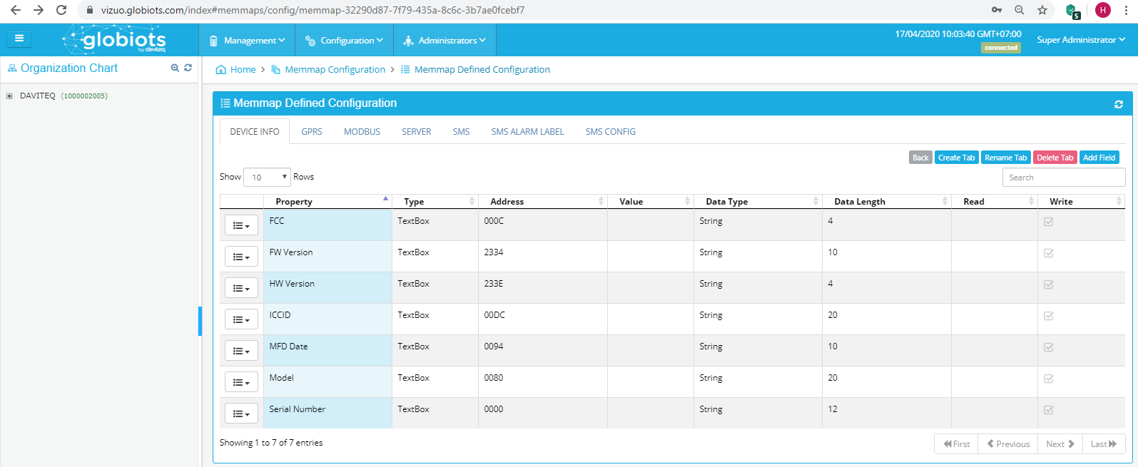
• FCC: IConnector's own secret code, used to register on Globiots
• FW Version: Software version
• HW Version: Hardware version
• ICCID: Seri number of SIM
• MFD Date: Date of manufacture
• Model: Product code
• Serial Number: The unique serial number of each iConnector, without duplication, is used to register on Globiots
(2) GPRS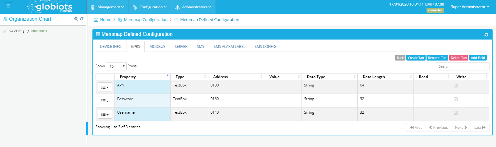
• APN: Access point of the network operator
• Password: Network password
• Username: Network username
(3) MODBUS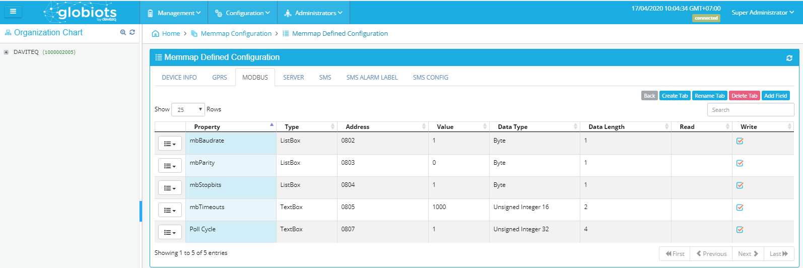
• mbBaudrate: Transmission rate, default "9600"
• mbParity: Error detection, default "None"
• mbStopbits: Stop bit, default "1"
• mbTimeouts: Timeout for slave response of a Modbus command
• Poll Cycle: Data update cycle
(4) Sever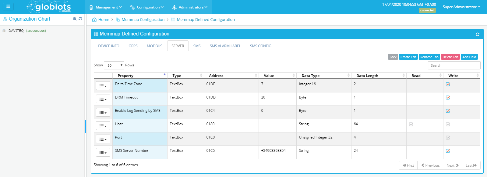
• Delta Time Zone: Time zone
• DRM Timeout: The time iConnector waits for the server to respond
• Enable Log Sending by SMS: The function of sending log by SMS
• Host: Domain name of server host
• Post: Domain name of server post
• SMS Server Number: Phone number iConnector will send a log by SMS to the server
• Poll Cycle: Data update cycle
(5) SMS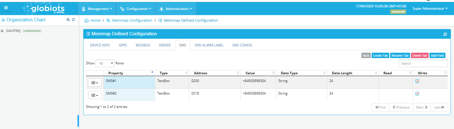
• SMS#1: Phone number 1 allows to record configuration of server and port
•SMS#2: Phone number 2 allows to record configuration of server and port
(6) SMS ALARM LABEL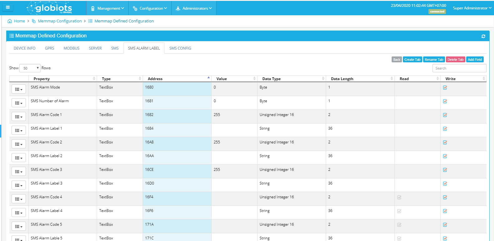
• SMS Alarm Mode: : = 1: Alarm SMS alarm from event, indicator when event from false to true
• SMS Number of Alarm: Number of SMS alarm (max 20)
• SMS Alarm Code 1..10: Set by event ID to notify SMS
• SMS Alarm Lable 1..10: The label of the message sent the alarm
(7) SMS CONFIG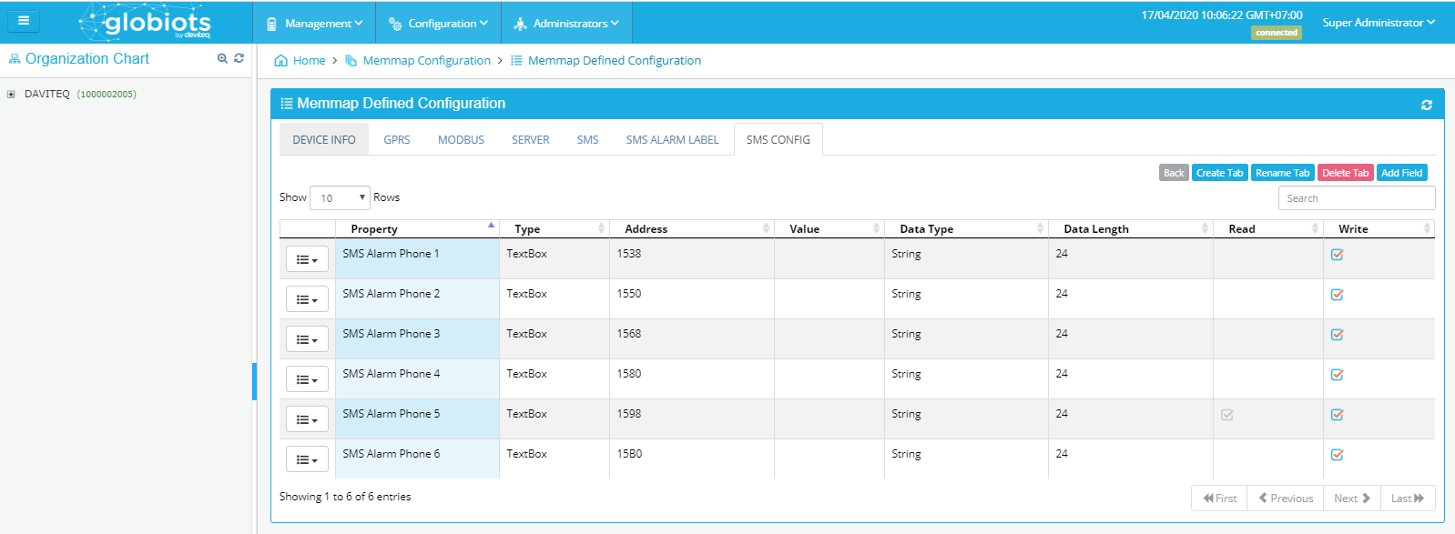
• SMS Alarm Phone 1..6: Phone number from 1 to 6
5.3 Create a new Device
To create a new Device:
(1) Select Node
(2) Right click and select “New”
(3) Click “Device” to create a new Device
(4) A box appears: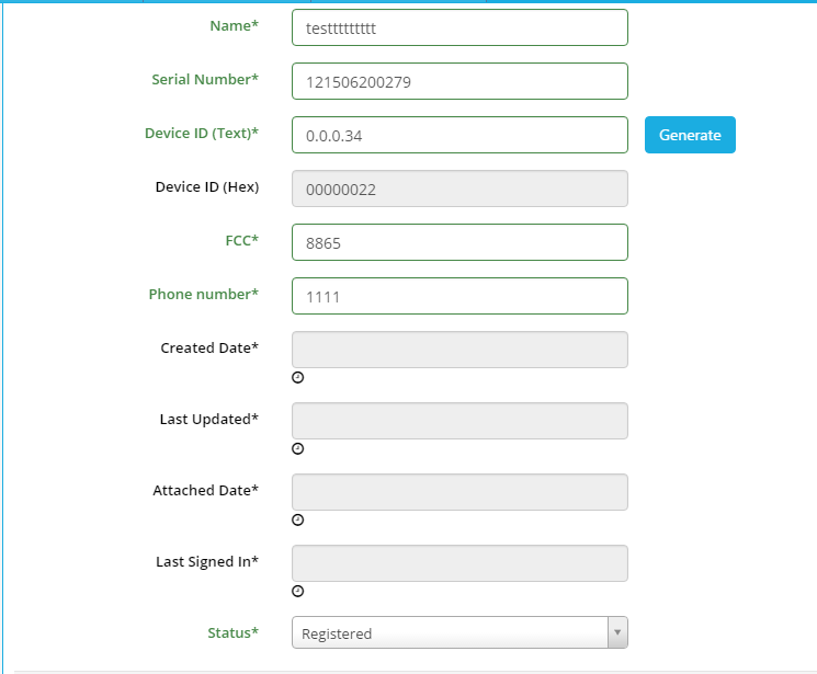
• Enter parameters of Device:
o Name: Name of Device (require 12 characters)
o Serial Number: provided by manufacturer (require 12 characters)
• Click “Generate” button to create Device ID or enter ID directly
• FCC: provided by manufacturer (require 4 characters)
• Phone number: Enter phone number of SIM in iConnector if available
• Click “Save” button to continue. A box appears: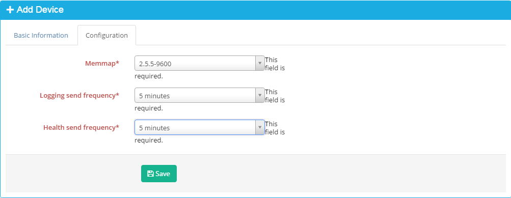
o Memmap: select memory map version provided by manufacturer
Note: In case Iconnector updates to a new Firmware, you need to update a new Memmap
To update a new Memmap:
(1) Double click Name of Device
(2) Click Configuration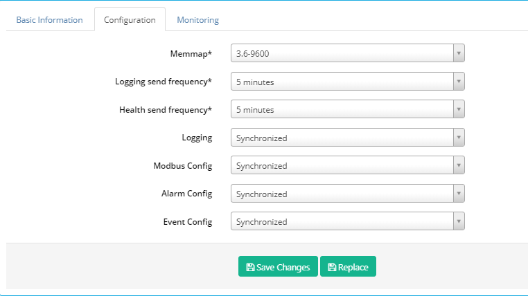
(3) Select new memory map version provided by manufacturer
(4) Click "Save Changes" to finish
o Logging send frequency: Frequency to send logged data from iConnector to server
o Heath send frequency: Frequency to send logged data about iConnector health from iConnector to server
Click “Save” to continue, click button OK to confirm, and enter admin user and password to verify permission
5.4 Delete Device
To delete a Device: Right click Device name and select Delete and click OK to confirm
5.5 Configure Parameter
Click on Device, right-click, select Parameter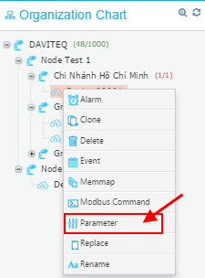
In List Parameters Page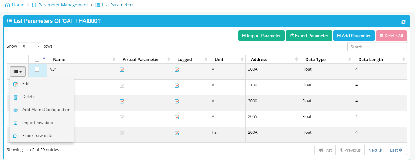
• “Import Parameter”: click to Import Parameters from excel file. Excel file must have default structure.
• “Export Parameter”: click to export parameter to excel file.
• “Add parameter”: click to add a new parameter.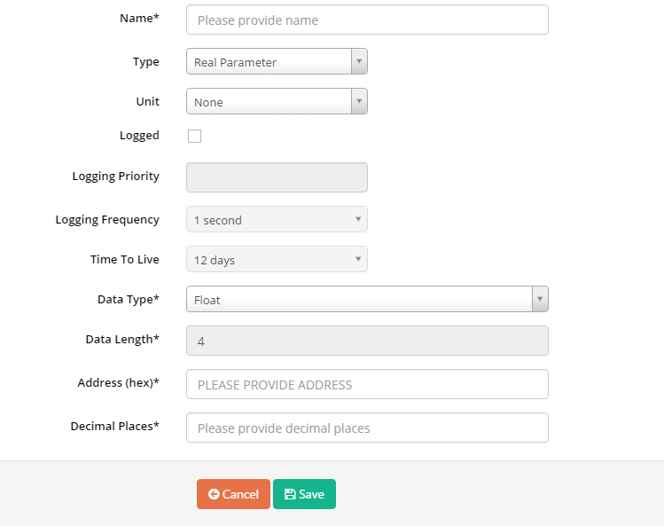
o Name: parameter name
o Type: Real Parameter or Virtual parameter
Real Parameter: Parameter from iConnector
Virtual Parameter: Parameter only in Server. Virtual parameter is create from formula of one or multi real parameter
If type is Virtual parameter, formula in Expression should be added
Mathematical Operators
|
Operator |
Description |
|
+ |
Additive operator / Unary plus |
|
- |
Subtraction operator / Unary minus |
|
* |
Multiplication operator, can be omitted in front of an open bracket |
|
/ |
Division operator |
|
% |
Remainder operator (Modulo) |
|
^ |
Power operator |
Boolean Operators
|
Operator |
Description |
|
= |
Equals |
|
== |
Equals |
|
!= |
Not equals |
|
<> |
Not equals |
|
< |
Less than |
|
<= |
Less than or equal to |
|
> |
Greater than |
|
>= |
Greater than or equal to |
|
&& |
Boolean and |
|
|| |
Boolean or |
Supported Functions
|
Function* |
Description |
|
NOT(expression) |
Boolean negation, 1 (means true) if the expression is not zero |
|
IF(condition,value_if_true,value_if_false) |
Returns one value if the condition evaluates to true or the other if it evaluates to false |
|
RANDOM() |
Produces a random number between 0 and 1 |
|
MIN(e1,e2, ...) |
Returns the smallest of the given expressions |
|
MAX(e1,e2, ...) |
Returns the biggest of the given expressions |
|
ABS(expression) |
Returns the absolute (non-negative) value of the expression |
|
ROUND(expression,precision) |
Rounds a value to a certain number of digits, uses the current rounding mode |
|
FLOOR(expression) |
Rounds the value down to the nearest integer |
|
CEILING(expression) |
Rounds the value up to the nearest integer |
|
LOG(expression) |
Returns the natural logarithm (base e) of an expression |
|
LOG10(expression) |
Returns the common logarithm (base 10) of an expression |
|
SQRT(expression) |
Returns the square root of an expression |
|
SIN(expression) |
Returns the trigonometric sine of an angle (in degrees) |
|
COS(expression) |
Returns the trigonometric cosine of an angle (in degrees) |
|
TAN(expression) |
Returns the trigonometric tangens of an angle (in degrees) |
|
COT(expression) |
Returns the trigonometric cotangens of an angle (in degrees) |
|
ASIN(expression) |
Returns the angle of asin (in degrees) |
|
ACOS(expression) |
Returns the angle of acos (in degrees) |
|
ATAN(expression) |
Returns the angle of atan (in degrees) |
|
ACOT(expression) |
Returns the angle of acot (in degrees) |
|
ATAN2(y,x) |
Returns the angle of atan2 (in degrees) |
|
SINH(expression) |
Returns the hyperbolic sine of a value |
|
COSH(expression) |
Returns the hyperbolic cosine of a value |
|
TANH(expression) |
Returns the hyperbolic tangens of a value |
|
COTH(expression) |
Returns the hyperbolic cotangens of a value |
|
SEC(expression) |
Returns the secant (in degrees) |
|
CSC(expression) |
Returns the cosecant (in degrees) |
|
SECH(expression) |
Returns the hyperbolic secant (in degrees) |
|
CSCH(expression) |
Returns the hyperbolic cosecant (in degrees) |
|
ASINH(expression) |
Returns the angle of hyperbolic sine (in degrees) |
|
ACOSH(expression) |
Returns the angle of hyperbolic cosine (in degrees) |
|
ATANH(expression) |
Returns the angle of hyperbolic tangens of a value |
|
RAD(expression) |
Converts an angle measured in degrees to an approximately equivalent angle measured in radians |
|
DEG(expression) |
Converts an angle measured in radians to an approximately equivalent angle measured in degrees |
Supported Constants
|
Constant |
Description |
|
e |
The value of e, exact to 70 digits |
|
PI |
The value of PI, exact to 100 digits |
|
TRUE |
The value one |
|
FALSE |
The value zero |
|
NULL |
The null value |
Note: Virtual parameter can't use for event.
Example 1: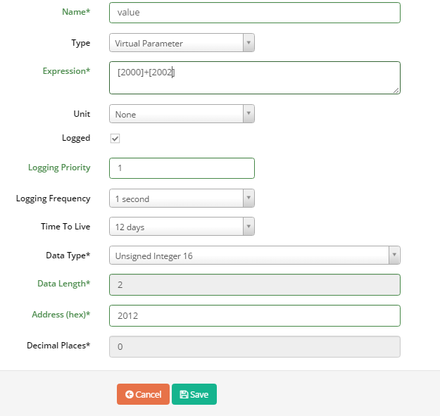 Value of Virtual Parameter have address at 2012 is calculated as follow [2012] = [2000] + [2002. ]In which address 2000 and 2002 are two real parameters
Example 2:
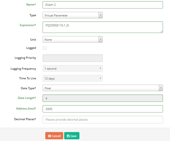
IF [2000]>10 then [2005]=1
IF [2000]<=10 then [2005]=2
Example 3:
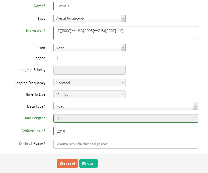
IF [2000]=1 And [2005]=2 then [2010]=5
IF [2000]=!1 And [2005]=!2 then [2010]=[2007]+10
Example 4:
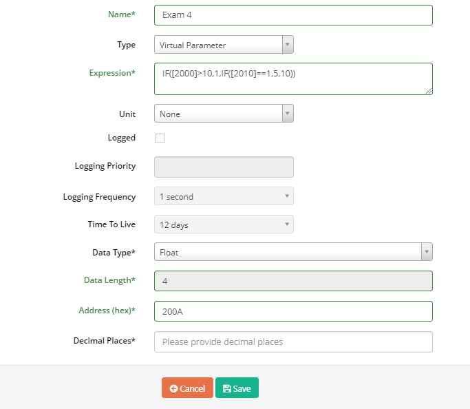
IF [2000]>10 then [200A]=1
IF [2000]<10 And [2010]=1 then [200A]=5
IF [2000]<10 And [2010]=!1 then [200A]=10
o Unit: Unit of parameter
o Logged: Tick to permit saving value of parameter into database
o Logging Priority: enter any value
o Logging Frequency: select frequency to log data from meter/sensor/device/instrument into iConnector memory
o Time to live: select how long data will be stored in database
o Data Type: Type of parameter
o Data Length: Length of data type, byte unit, display automatically with data type. If data type is String, data length should be input
o Address: Address in iConnector memory map to store value of parameter
o Decimal Places: number of decimal after the comma.
• Save: click to finish
• “Delete All”: click to delete selected parameters
• Edit: click to edit this parameter
• Delete: delete parameter
• Add Alarm Configuration: Click to add Alarm for parameter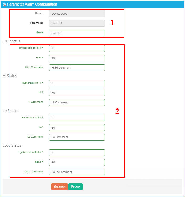
o (1) Display Device name & Parameter.
o (2) Enter Alarm value:
Hysterisis of HiHi, Hysteresis of Hi, Hysteresis of Lo, Hysteresis of LoLo: Enter any value, there are 4 level for Alarm.
HiHi: Value at very high level.
HiHi Comment: Comment of very high level.
Hi: Value at high level.
Hi Comment: Comment of high level
Lo: Value at low level.
Lo Comment: Comment of low level.
LoLo: Value at very low level.
LoLo Comment: Comment of very low level.
o Click “Save” button and then click button OK to save Alarm Configuration for parameter.
Note: After Configure Parameter, you must synchronize (refer to 5.11 Synchronize Device for more details)
5.6 Configure Modbus Command
- Select Device, right-click, select Modbus Command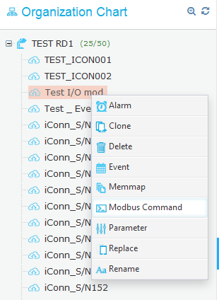
- Modbus Configuration page displays as below: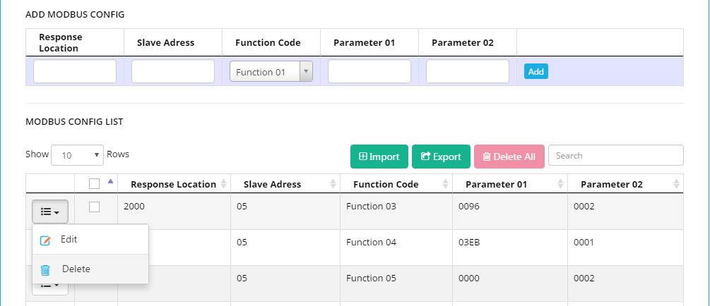
• MODBUS CONFIG LIST (1)
o Button “Edit”: click to edit Modbus Command. Modbus Command will display in (2) to edit
o Button “Delete”: click to delete Modbus Command.
o Button “Import”: click to import Modbus Command list from excel file
o Button “Export”: click to export Modbus Command list to excel file
o Button “Delete All”: click to delete all Modbus Command
• ADD MODBUS CONFIG (2)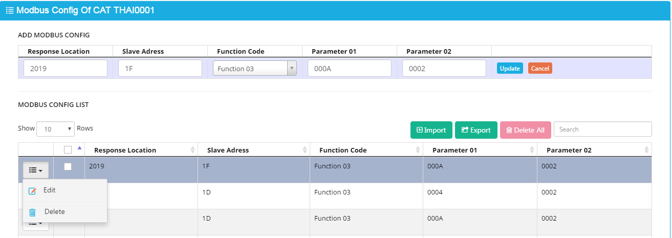
o Response Location: Address of parameter in iConnector
o Slave ID: Modbus ID of meter/sensor/device/instrument which connect to iConnector through RS485 port
o Function Code: Function Code of Modbus Command. Function Code consist of read function and write function. In user manual of meter/sensor/device/instrument should mention supported function code.
o Parameter 01: Starting address of parameter in memory map of meter/sensor/device/instrument
o Parameter 02: Number of registers of parameter in memory map of meter/sensor/device/instrument
o Button “Add”: Click to add new Modbus Command
o Button “Update”: After click “Edit” button in (1), “update” will display. After editing Modbus command and click “Update” to save change.
Note:
Response Location in iConnector for read Modbus data :0x2000 -> 0x21FF
Response Location in iConnector for write Modbus data: 0x3000 -> 0x307F
After configuring, Modbus Command should be synchronized to iConnector (refer to 5.11 Synchronize Device for more details)
Example:
Configure modbus command for reading parameter Voltage, data type: float, from address 0000 on power meter (ID=32) and store at address 2000 on iConnector, using function 04 of modbus command. The configuration as follow:
Explanation:
ID=32 (decimal) =20 (Hexa) = Slave Address
Parameter 01 = Start Address = 0000
Parameter 02 = Number of register of parameter. Data type = float (4 bytes) = 02 register
5.7 Configure Alarm
- To configure Alarm: Right click Device name and select Alarm. “List Alarms” page appears: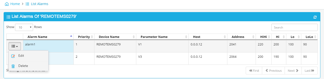
• Click “Edit” to edit alarm (refer to 5.4 Configure Parameter → Add Alarm Configuration for more details)
• Click “Delete” to delete alarm
Note: After configure Alarm, synchronization must be done (refer to 5.11 Synchronize for more details)
5.8 Configure Event
To configure Event: right click Device name and select Event. “The List Of Event” page displays as below: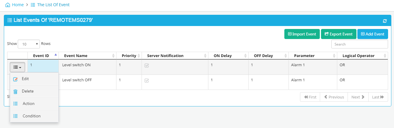
• Import Event: Import event from excel file
• Export Event: Export event to excel file
• Add Event: click to add a new event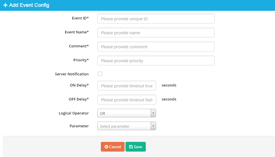
o Event ID: from 1 to 127 (event ID is only)
o Event name: name of event
o Comment: explain for event
o Priority: Any value
o On Delay: Delay time (second) when condition is true
o Off Delay: Delay time (second) when condition is false
o Logical Operator (AND/OR): Logical Operator for conditions of event
o Parameter: select parameter sent to server when event occur. Only display Real Parameter
o Click “Save” to finish
• Edit: Click to edit event
• Delete: Click to delete event
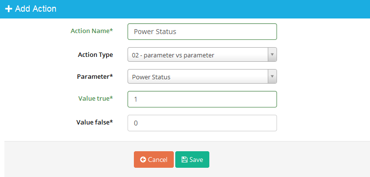
• Action: Click to configure action for event. An event might have some actions. The List of Actions page displays: 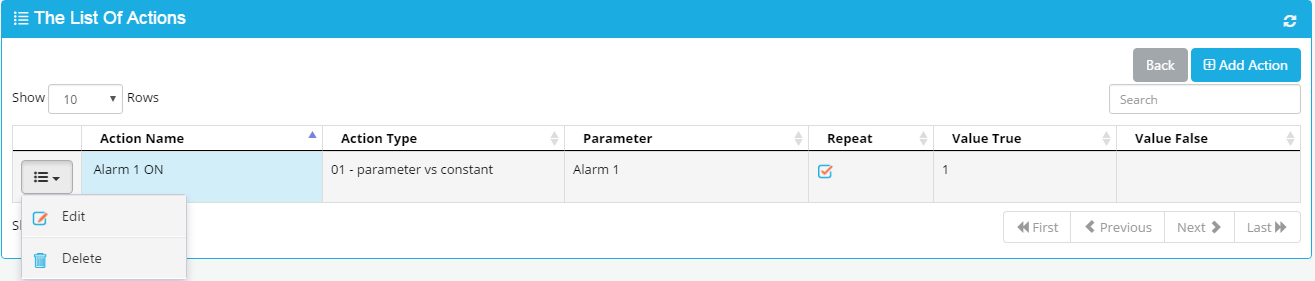
o Add Action: click to add a new action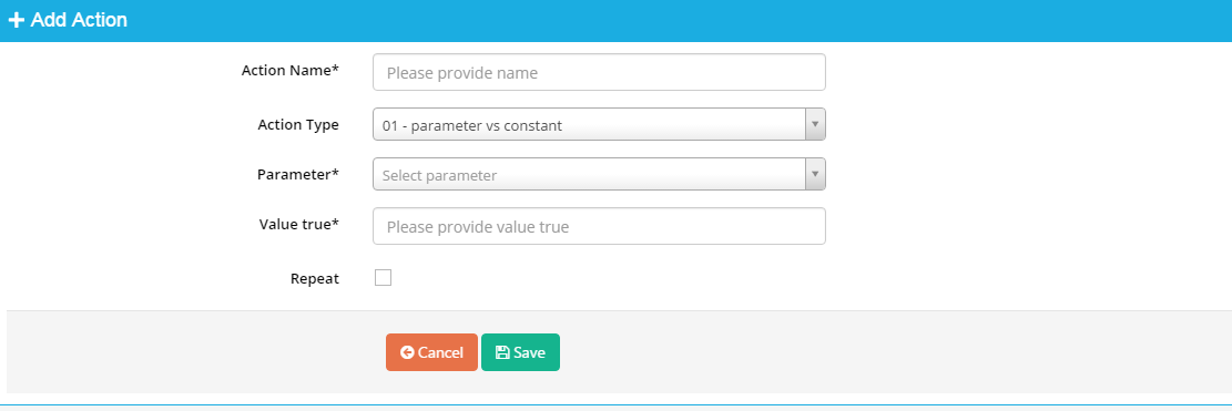
Action Name: Name of Action
Action Type: Select type of Action. There are 04 type of available action
1. Type 1: 01- Parameter vs constant: Action to assign constant to parameter if condition is true
2. Type 2: 02-parameter vs parameter: Action to assign constant to parameter if condition is true and false
3. Type 3: Action to assign value of source parameter to value of destination parameter if condition is true
4. Type 4: Action to assign value of source parameter to value of destination parameter if condition is true and false
Repeat: tick to implement action once condition is still true. If Repeat: is not ticked, the action only is implemented when condition from FALSE to TRUE.
Value true: constant assigned to parameter when condition is true
Value false: constant assigned to parameter when condition is false
Write Parameter: Destination parameter which is assigned value
Read Parameter: Source parameter
True Parameter: Source parameter if condition is true
False Parameter: Source parameter if condition is false
Save: click “save” to finish
o Edit: click to edit action of event
o Delete: click to delete action
Note: Written parameter in action must have address in range 3000-307F
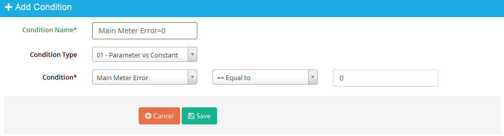
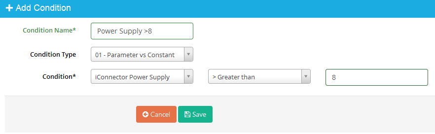
• Condition: click to configure condition of event. An event might have one or multi conditions. Value of total condition is formed from logical operator of multi conditions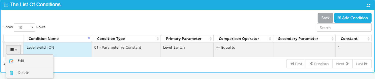
o Add Condition: click to add new condition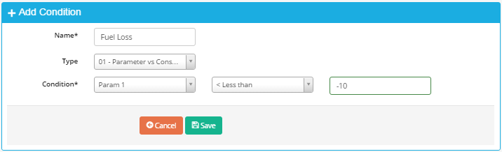
Condition Name: Name of condition
Condition Type: Type of condition. There are 3 types of condition
+ Type 1: 01- Parameter vs constant: Compare value of parameter to constant
+ Type 2: 02-parameter vs parameter: Compare value of parameter to value of another parameter
+ Type 3: 03- Parameter (bit) vs constant: Compare value of bit complex of parameter to constant
Condition: Compare value of a parameter to constant or value of a parameter to value of another parameter. Compare Operators are less than, less than or equal to, equal to, not equal, greater than, greater than or equal to
Click “Save” to finish
o Edit: click to edit condition of event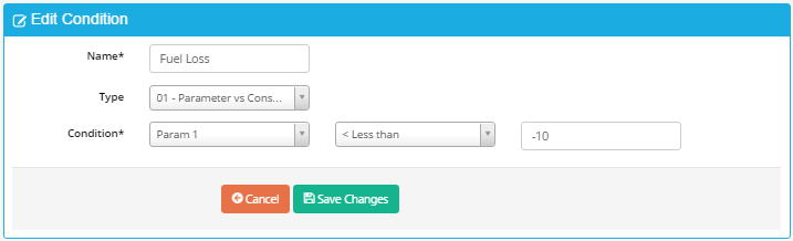
o Delete: click to delete a condition of event
Note:
Each Event have maximum 8 conditions
After configure Event, you must synchronized (refer to 5.11 Synchronize Device for more details)
Example:
Configure Event to create parameter Power Status:
Power Status =1 when iConnector Power Supply > 8 VDC and Main Meter Error=0 in
more than 2s.
Power Status=0 when iConnector Power Supply <=8 and Main Meter Error=0 in more
than 3 s.
When event occur, event will be sent to server
Configuration for this event, condition and action as follow: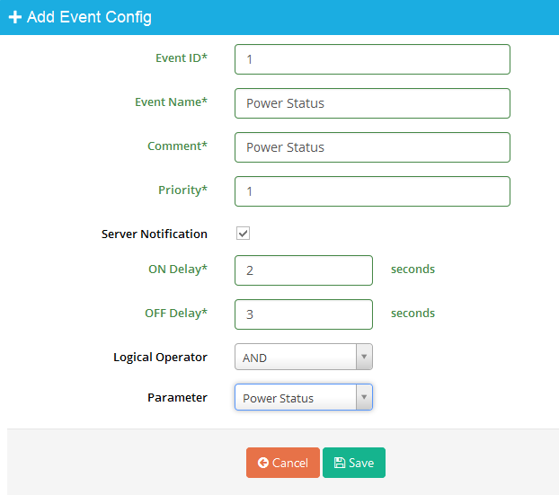
5.9 Clone Device
To create a new Device have same Parameters, Alarm Config, Modbus Command, Menmap, Event Configure …, select original Device, right-click, select “clone”. Below page appears
Refer to 5.2 “Create a new Device” for more details.
5.10 Replace Device
To replace Device:
• Right click Device name and select Replace
• A box displays: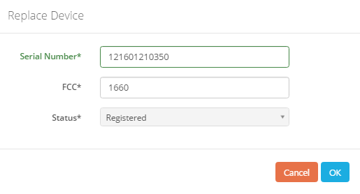
o Enter serial number and FCC of new Device
o Click “OK” to continue
• A box appears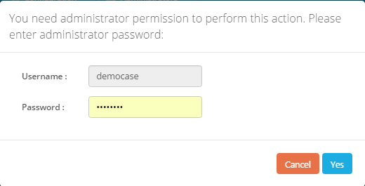
Click “Yes” to finish
5.11 Rename Device
To change name of Device: Right click Device name, select Rename, and enter new name
5.12 Synchronize Device
To change name of Device: Right click Device name, select Synch, and tick type of configuration to synchronize to iConnector, click Sync, enter password to confirm permission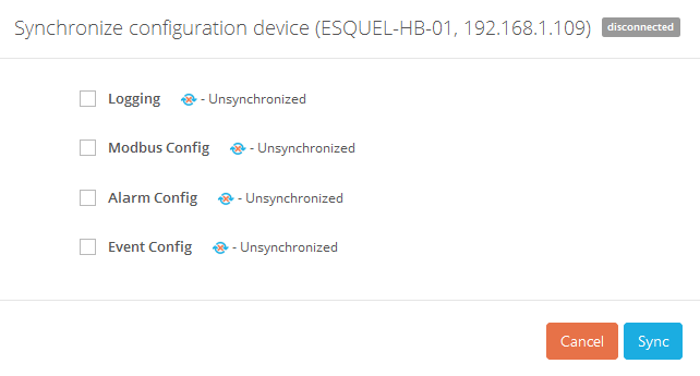
After successful synchronization, Text Synchronized should appear on 4 line of dialog box. If iConnector disconnected, message should appear to inform that synchronization will implement once iConnector connect to server.
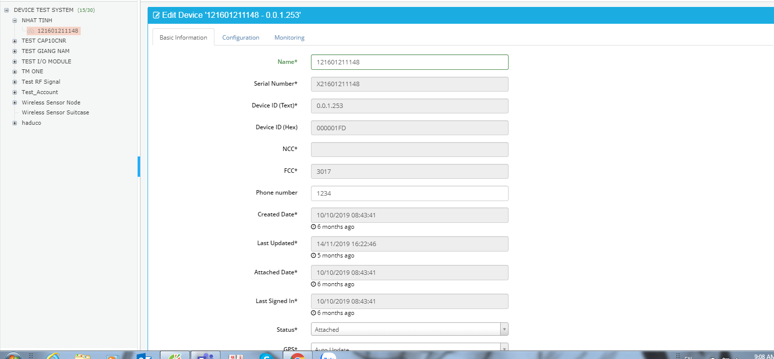
5.13 Edit Device
To Edit Device, click Device, “Edit Device” page appears as follow: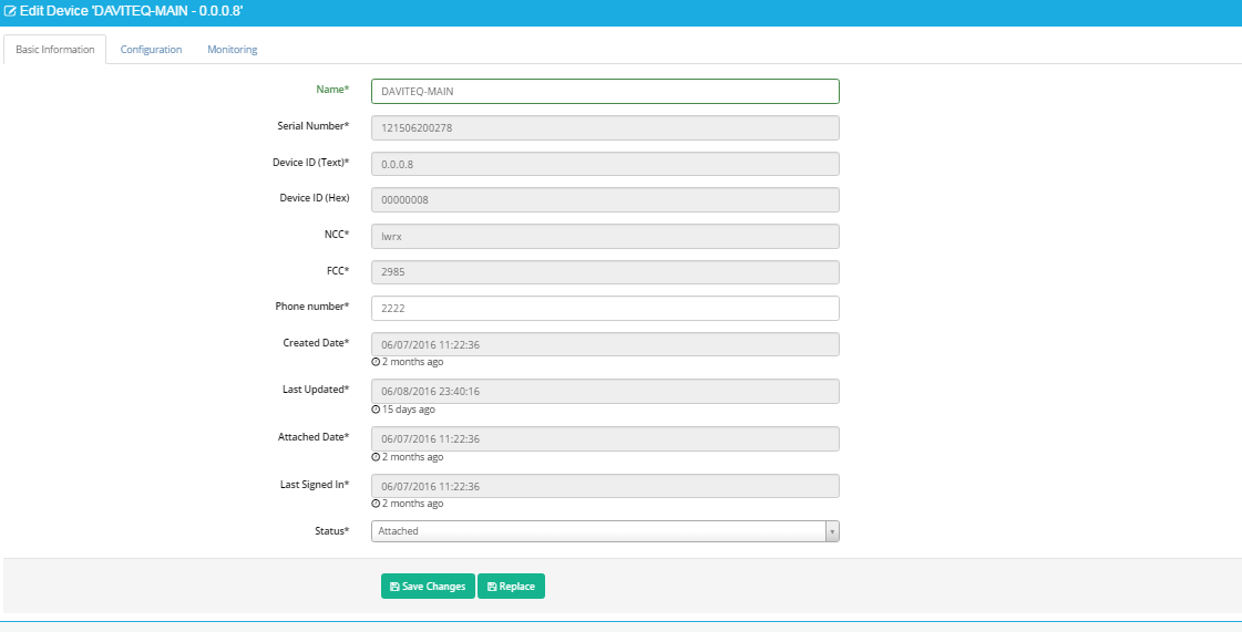
5.13.1 Basic information
To view and edit basic information of Device, In Edit Device page, select Basic Information Tab. 
• Click “Replace” to change a new Device (refer to 5.9 Replace for more details)
• Click “Save Changes” to save
5.13.2 Configuration
In Edit Device Page, select Configuration Tab.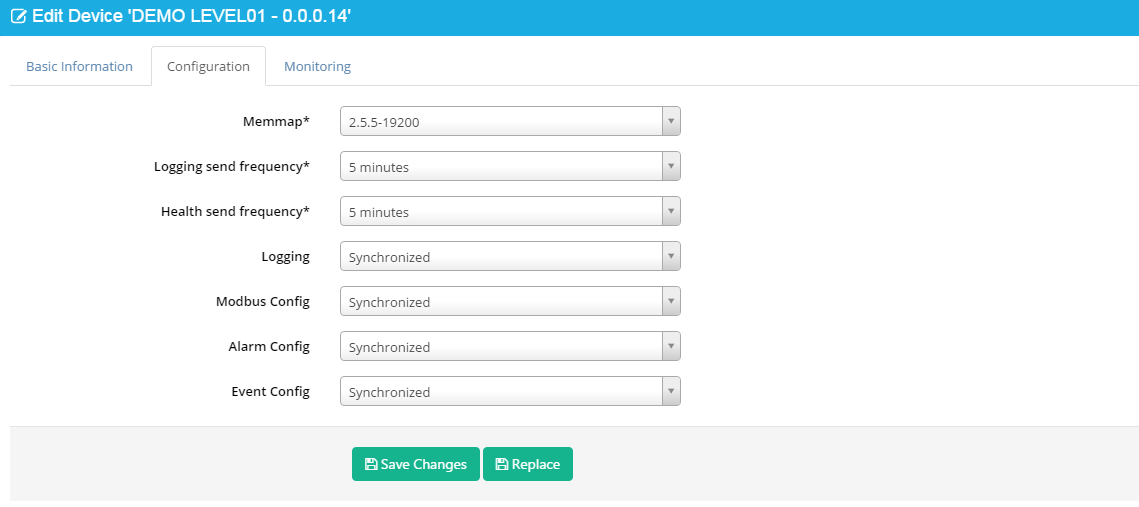
• Memmap: Memmap version of iConnector
• Logging send frequency: frequency to send logged data from iConnector to server
• Heath send frequency: frequency to send logged data about iConnector health from iConnector to server
• Logging: synchronize status of logged parameters.
Select “Unsynchronized” and click Save Changes after changing parameter configuration to synchronize new parameter configuration from server to iConnector
• Modbus Config: synchronize status of modbus command.
Select “Unsynchronized” and click Save Changes after changing Modbus Command configuration to synchronize new Modbus Command configuration from server to iConnector
• Alarm config: synchronize status of alarm configuration
Select “Unsynchronized” and click Save Changes after changing alarm configuration to synchronize new alarm configuration from server to iConnector
• Event config: synchronize status of event configuration
Select “Unsynchronized” and click Save Changes after changing event configuration to synchronize new event configuration from server to iConnector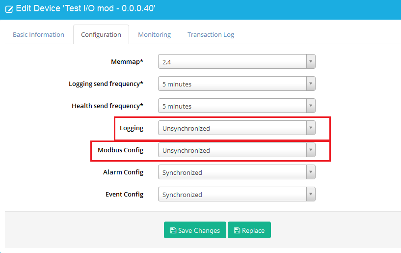
5.13.3 Monitoring
In Edit Device Page, select Monitoring Tab.
• Health Status: display Connection status between iConnector and server ( Connected/Waiting for connect/Disconnected)
• Config Status: display synchronization status (Synchronized or Unsynchronized)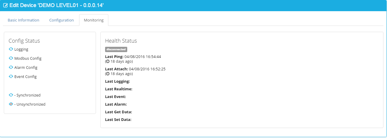
6. Management
6.1 Dashboard
6.1.1 Dashboard Description
Dashboard views input text, current value and value from database. Each Dashboard is organized in one tab. When value is from database, dashboard will update the value after specific time. Dashboard consists of containers which contain widgets inside.
6.1.2 View Dashboard
- In Home screen, select menu Management → select sub-menu Dashboard to display current value of parameters.
- Screen of status “Dashboard”: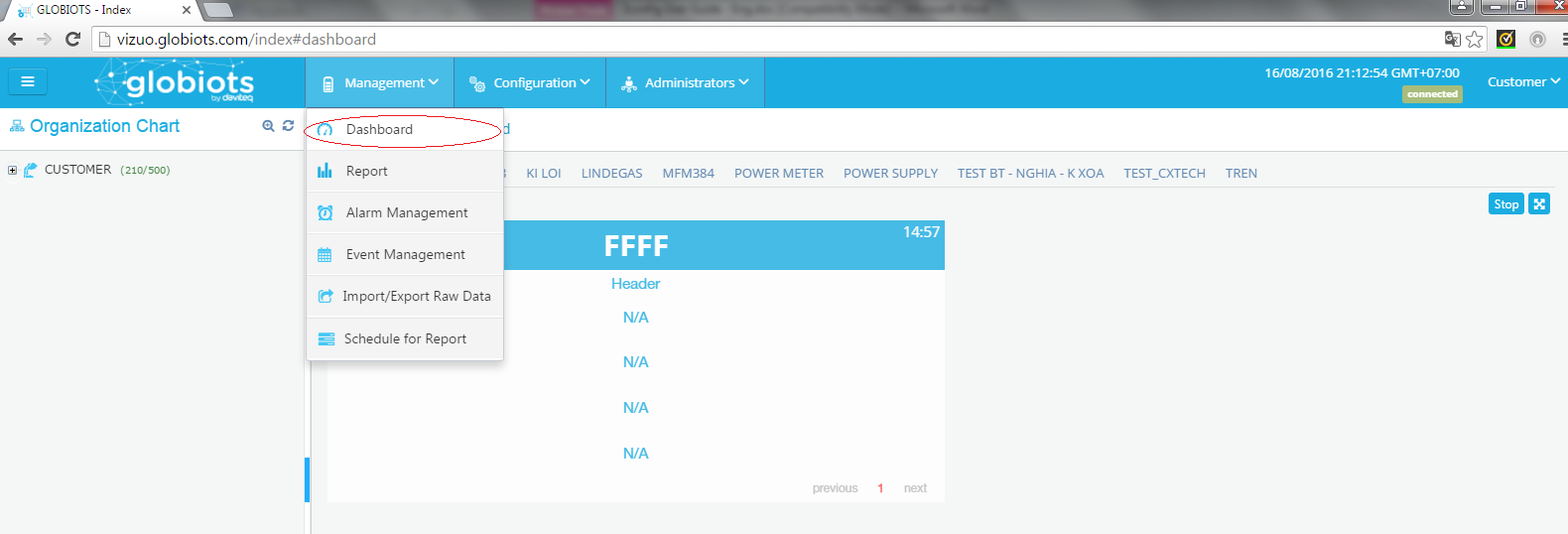
- Screen of status “Stop” of Dashboard: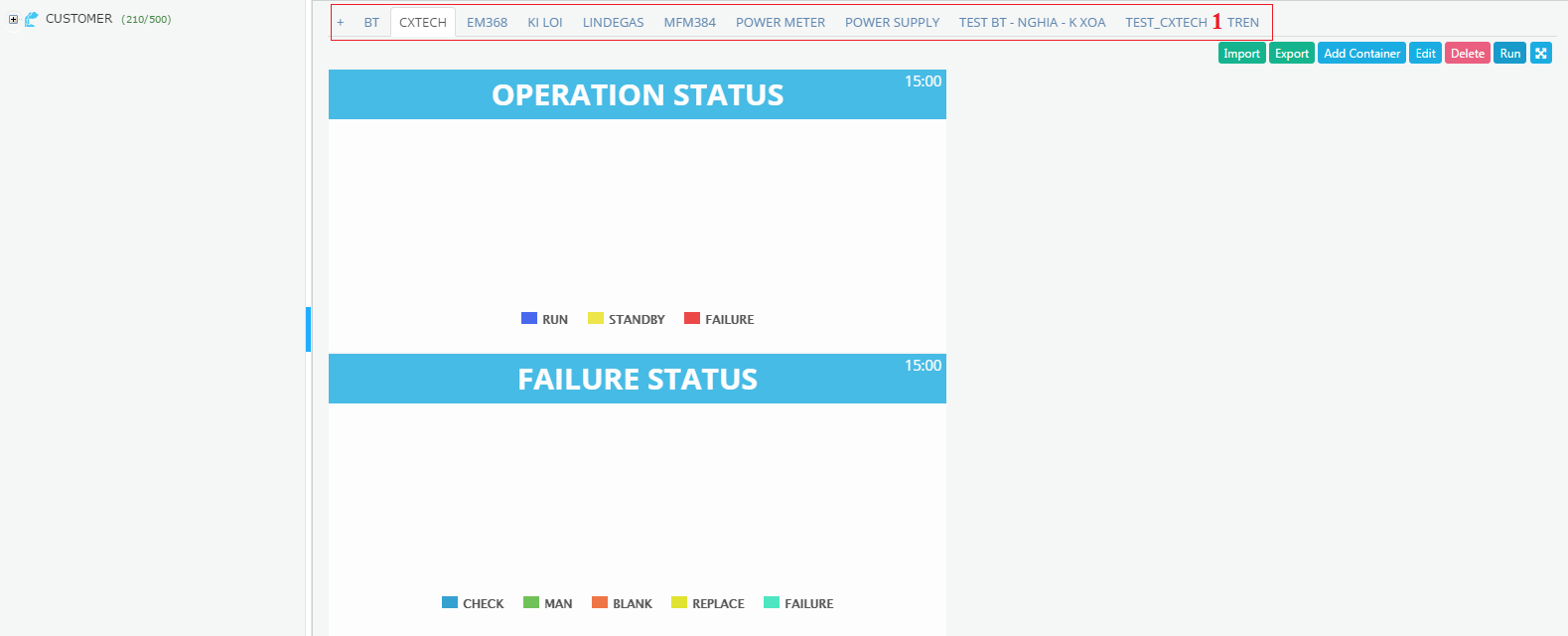
• (1): Display list of Dashboard tabs which user are assigned to view
• Button “Run”: click to run Dashboard.
• Button “Stop”: click to stop selected Dashboard.
• Button “Delete”: click to delete Dashboard
• Button “Edit”: click to edit Dashboard
• Button “Add Container”: click to add new Container in Dashboard
• Button  : click to fullscreen
• Button “Export”: click to export Dashboard to Excel File
• Button “Import”: Click to import Dashboard to Excel File
6.1.3 Create new Dashboard
- In Dashboard screen, click symbol “+” to create new tab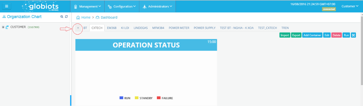
- New window display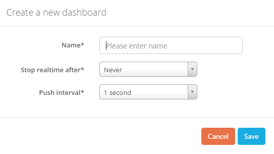
• Name: Name of new Dashboard tab
• Stop realtime after: Running time of Dashboard to get realtime data from iConnector. After this period of time, Dashboard will stop to get realtime data from iConnector.
Click button “Run” on top right corner to continue to get realtime data
• Push Interval: Frequency to get realtime data from iConnector
Click Save to complete creating new Dashboard
6.1.4 Create New Container
- In Dashboard tab, click Add Container to add new Container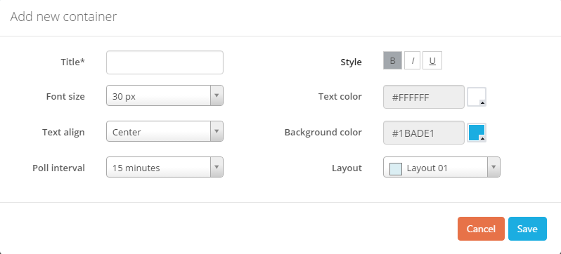
• Title: Name of container
• Format: Font size, Style, Text color, Text align, Background.
• Poll Interval: Frequency to get logged data from database to view on Dashboard
• Layout: Select layout of container. There are 07 layouts select
Click Save to complete creating Container
6.1.5 Configure a Container
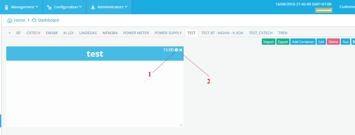
(1): Edit Container
(2): Delete container.
Click  to Edit Container. Following screen will appear
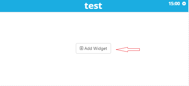
- Click Add Widget to add new widget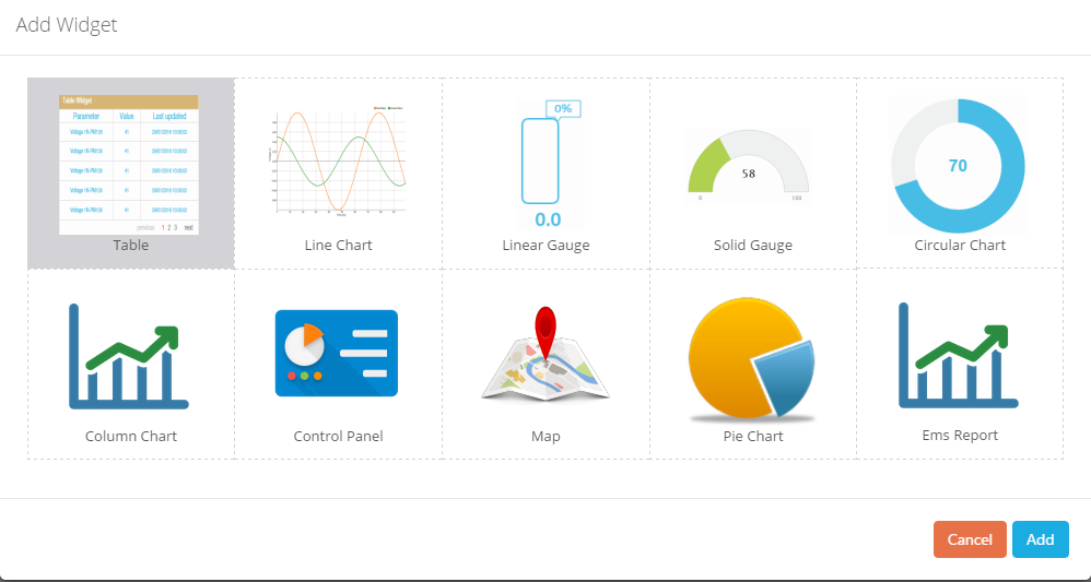
Note: Stop Dashboard before configure Container/Widget
6.1.6 Widget
6.1.6.1 Widget Description
Widget is a basic element of Dashboard to view constant, value of parameter. Currently, Vizuo has below widgets 
After select widget click Add to add new widget to Container
6.1.6.2 Widget Table
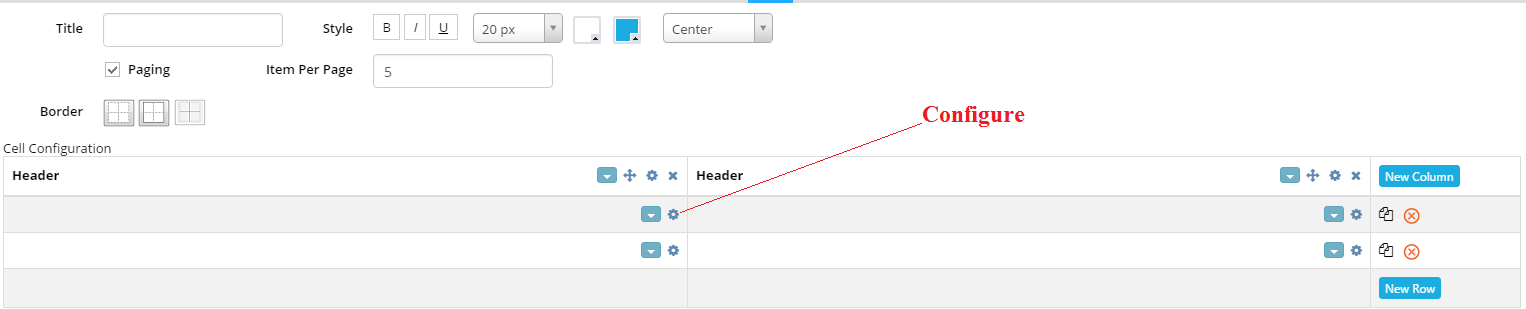 - Paging: Tick to view table more than one page
- Border: Select type of border: None, Border and Inside
- New Column: Click to add new column
- New Row: Click to add new row
•  : Move column
•  : Configure cell
•  : Close/Delete column or row
•  : Copy new row
•  : Click to select type of border for cell
- Configure Row
- After clicking , configuration screen for new row will appear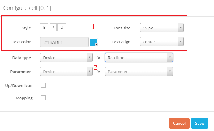
(1): Format
(2): Configure
Choose Data type: Constant (input text), Data from Database (Device Name, Parameter Name, Unit of Parameter, Last value of parameter in Database, time stamp of last value), Data from device (Realtime Data or Current Data). Realtime data is data push from iConnector and Current Data is data pull from iConnector
Up/down icon: Tick to add up/down icon. Up icon appears when last value is less than current value whereas down icon appears when last value is greater than current value. These icons are available when realtime data is displayed in cell
Mapping: tick Mapping and list out value and mapped text, then click  to add mapping value. Mapping should be used to view meaningful text instead of value

6.1.6.3 Widget Line Chart
Click to configure widget Line Chart, the following screen appear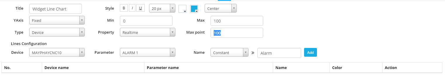
• Title: Line Chart name
• Style: Format of Title
• YAxis: Fixed or Auto. If choose Fixed, enter min & max value. If select Auto, software will specify Max of Y axis based on value of displayed parameter.
• Type: Data type of parameter to view (Data from device or from database)
Type Device: Realtime data and display Max point value on line chart
Type Database: Logged data from database, time period include:Today, Yesterday, Last 3 days or Custom (From…To)
• Line configuration: Select displayed parameter and displayed label (input text, parameter name or device name)
Click Add button to add parameter to line chart. A line chart could view
some parameters
6.1.6.4 Linear Gauge
Click to configure widget Line Gauge, the following screen appear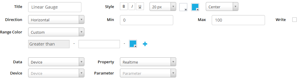
• Title: Name
• Style: Format of title
• Direction: Vertical or Horizontal Linear Gauge
• Min, Max: Range of Gauge
• Range Color: Auto or Custom
Auto: Color of Gauge changes according to value of parameter
Custom: Configure specific color to specific range of value of parameter
• Data: Select type of display parameter (last logged data from Database or current value/realtime value from Device
• Device/Parameter: Select displayed parameter
• Write: Tick to enable to write value to parameter. Writing value to parameter by holding and drag on body of Linear Gauge
Click Save Changes to complete configuration
6.1.6.5 Solid Gauge
Click to configure widget Solid Gauge, the following screen appear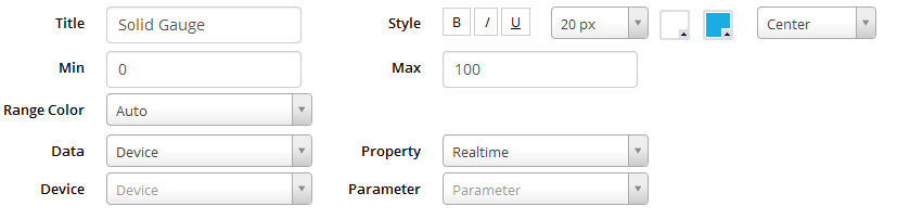
• Title: Name
• Style: Format of title
• Min, Max: Range of Gauge
• Range Color: Auto or Custom
Auto: Color of Gauge changes according to value of parameter
Custom: Configure specific color to specific range of value of parameter
• Data: Select type of display parameter (last logged data from Database or current value/realtime value from Device
• Device/Parameter: Select displayed parameter
Click Save Changes to complete configuration
6.1.6.6 Circular Chart
Click to configure widget Solid Gauge, the following screen appear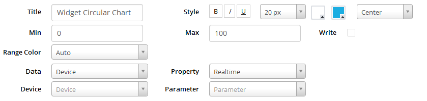
• Title: Name
• Style: Format of title
• Min, Max: Range of Chart
• Range Color: Auto or Custom
• Auto: Color of Chart changes according to value of parameter
• Custom: Configure specific color to specific range of value of parameter
• Data: Select type of display parameter (last logged data from Database or current value/realtime value from Device)
• Device/Parameter: Select displayed parameter
• Write: Tick to enable to write value to parameter. Writing value to parameter by holding and drag on body of Circular Chart
Click Save Changes to complete configuration
6.1.6.7 Column Chart
Click to configure widget Solid Gauge, the following screen appears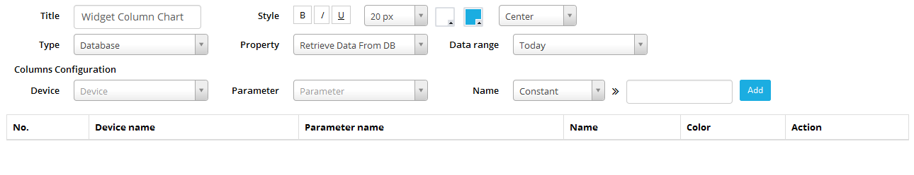 • Title: Column Chart name
• Style: Format of Title
• Type: Data type of parameter to view (Data from device or from database)
• Type Device: Realtime data
• Type Database: Logged data from database, last value or value series in time period include: Today, Yesterday, Last 3 days or Custom (From…To)
• Column configuration: Select displayed parameter and displayed label (input text, parameter name or device name)
Click Add button to add parameter to column chart. A column chart could view some parameters
6.1.6.8 Control Panel
Click to configure widget Control Panel, the following screen appears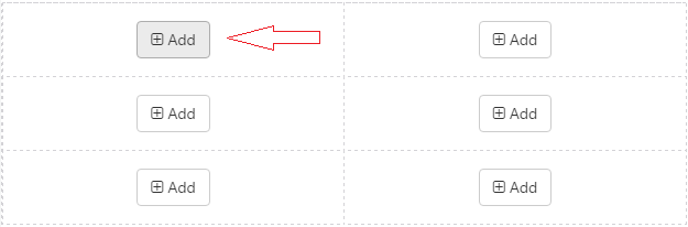

• Tittle: Name of Control Panel
• Style: Format for tittle
• Column: Number of column of Control Panel
• Row: Number of row of Control Panel
• Click Add button to add new symbols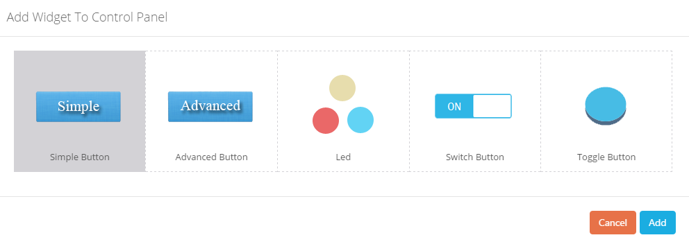
Choose one symbol and click Add
• Configure Simple Button
After adding Simple Button, following screen appear: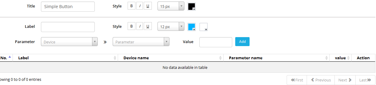
• Tittle: Name of Button
• Style: Format of Tittle/Label
• Label: Label on Button
• Parameter: Select written parameter. This parameter should have address in range 3000-307F
• Value: Value to write to parameter. If this value is blank, when the button is clicked the user should enter the value.
Click Add to add button. User could add some buttons in one widget
• Configure Advanced Button
After adding Advanced Button, following screen appear: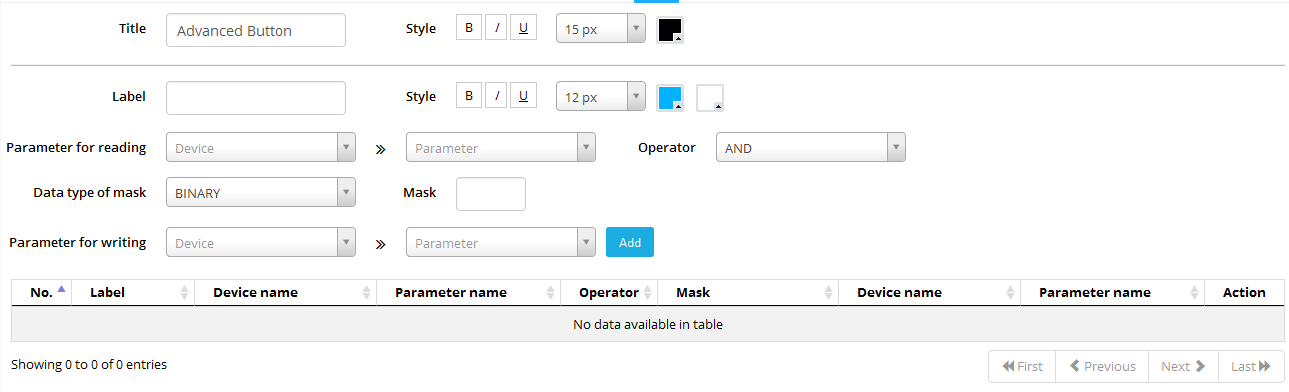
• Tittle: Name of Button
• Style: Format of Tittle/Label
• Label: Label on Button
• Parameter for reading: Select reading parameter.
• Operator: Logical Operator of Reading parameter and mask
• Mask: Mask to calculate written value. Mask format is binary or Hexa
• Parameter for reading: Select written parameter. This parameter should have address in range 3000-307F. Written value is the result of reading value and mask with logical operator
Click Add to add button. User could add some buttons in one widget
• Configure Led
Led will change its color when parameter changes value.
After adding Advanced Button, following screen appear: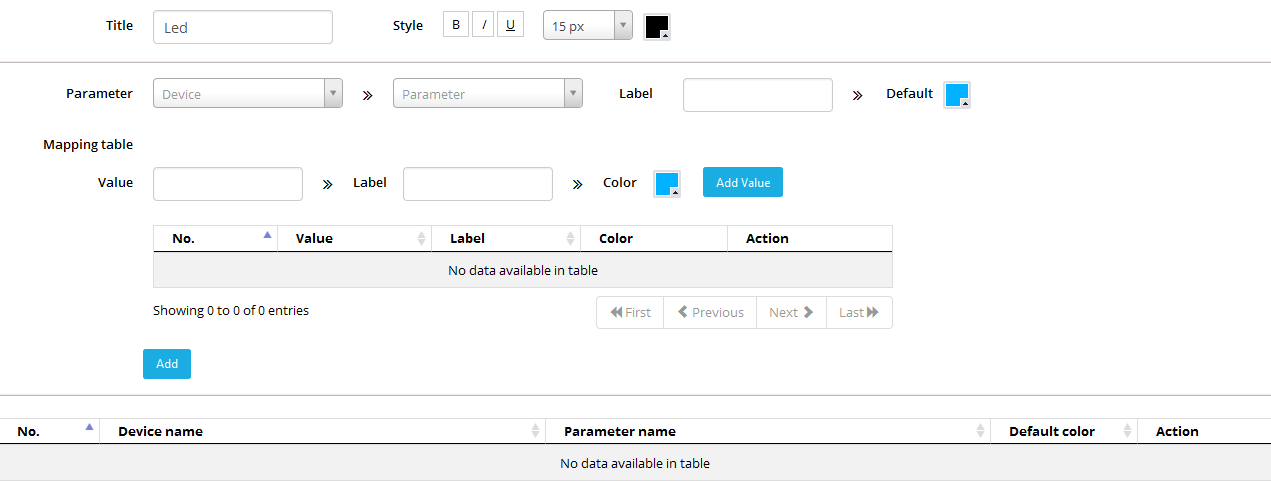
• Tittle: Tittle of LED
• Style: Format of LED tittle
• Parameter: Selcel Parameter to display
• Label: Label for LED
• Mapping Table: Define list of displayed label and color according to value of parameter
• Click Add to add LED
6.1.6.9 Map
Map shows location of iConnector (longitude and latitude) on map
Click to configure widget Map, the following screen appear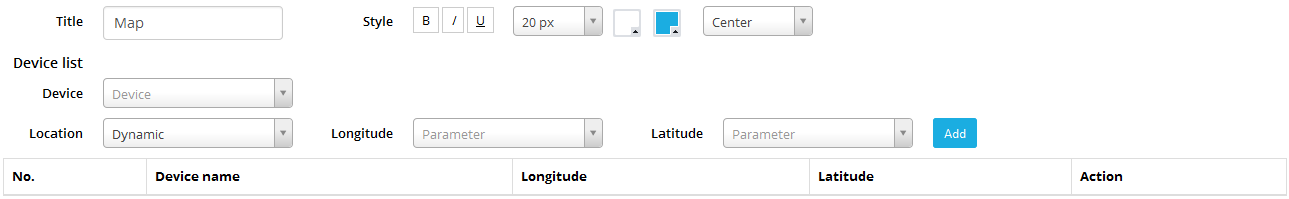
• Tittle: Name of Map
• Style: Format of Tittle
• Device List: iConnector list to display location (longitude and latitude)
• Device: Select iConnector name
• Location: Configure longitude and latitude parameter. Location are static or dynamic
If location is static, user enter value of longitude and latitude
If location is dynamic, configure longitude and latitude parameter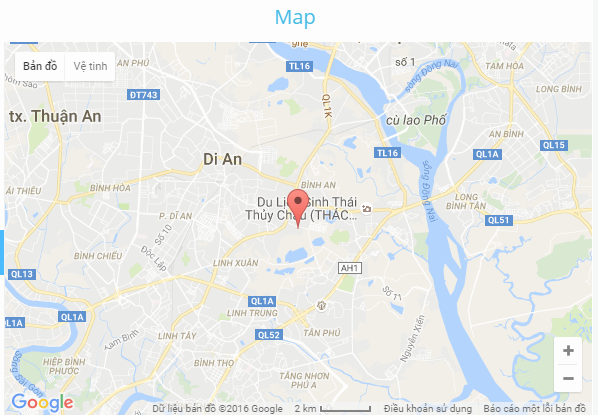
6.1.6.10 EMS Report
EMS Report views report for energy consumption during period of time
Click to configure widget EMS report, the following screen appears:
• Tittle: Report title
• Style: Format of tittle
• Report type: Daily, Weekly, Monthly
• Data range: Today, yesterday, last month, this month, last week, this week
• Column Configuration: Configure displayed value of parameter and displayed name of parameter
Click Add to add parameter for report
6.1.6.11 Pie Chart
Pie Chart compares values between some parameters. Click to configure widget EMS report, the following screen appears: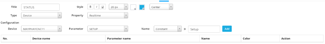
• Tittle: Tittle of pie chart
• Style: Format of tittle
• Type: Data type, realtime data or current value of device or last value in database
• Configuration: Configure displayed value and displayed name of parameter
6.2 Report
6.2.1 Create a new report
- To create a new report:
• In menu Management, select Report
• In Report page select “+ ” to create a new tab 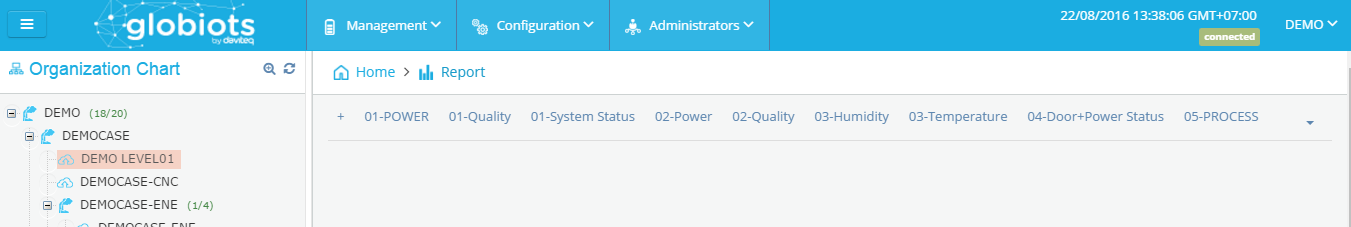
• Report Page will display as follow: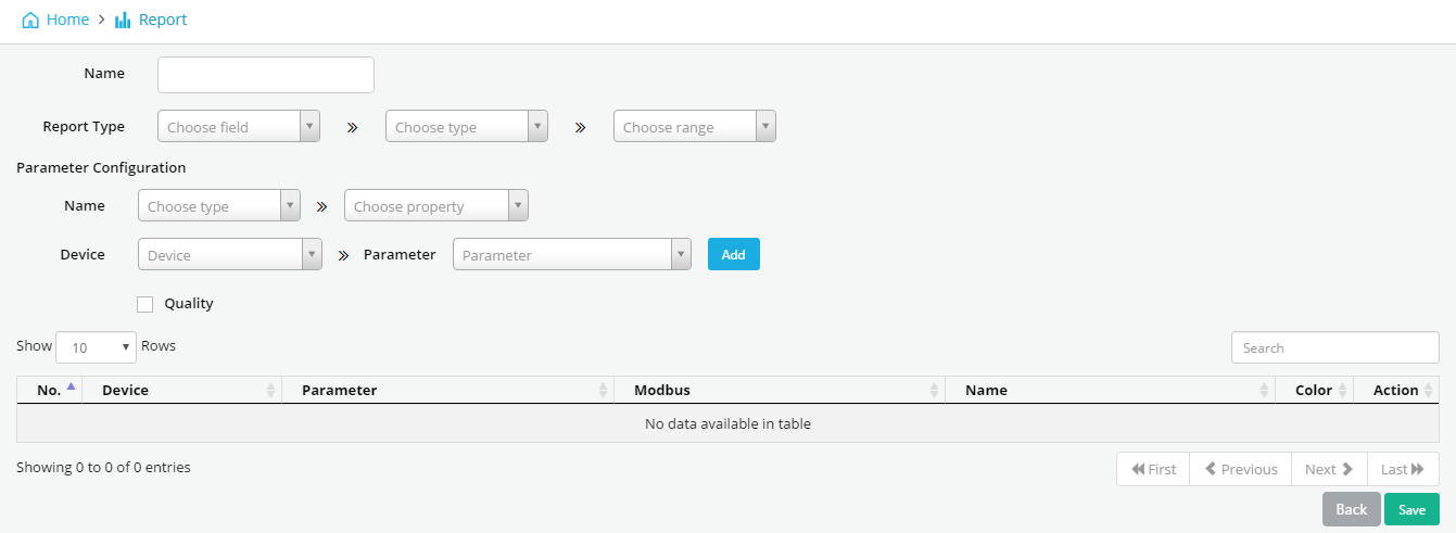
Enter full information
o Name: Name of Report tab
o Report Type: EMS (for energy), CNC (for CNC machine), Historical Trending (for parameter trend)
o Parameter Configuration:
Name: Name of parameter which display in report. Name might input text or name of parameter.
Device: select Device
Parameter: select parameter of device which you want display
Click “Add” to add parameter. A report might have some parameter
o After complete adding parameter, click “save” to finish
6.2.2 Configure Report
- In Report page, select Report name which you want configure
• Click “Delete” to delete report
• Click “Edit” to edit report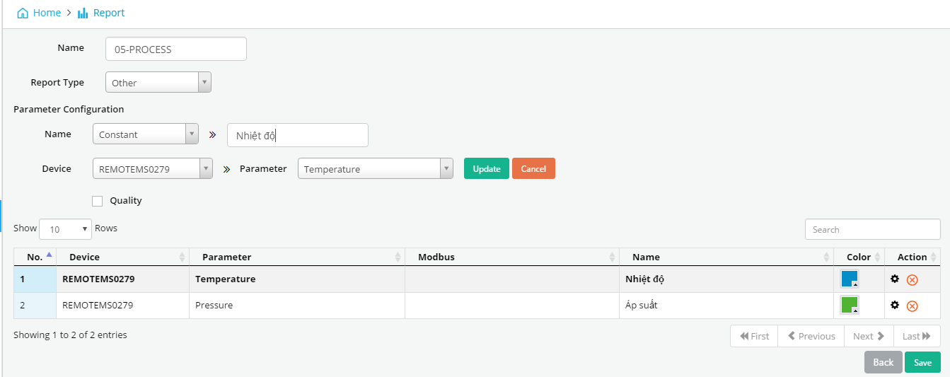
To edit available parameter, click in Action column, edit parameter, click Update
To delete parameter, click in Action
To Add new parameter: enter full information and click “Add”
6.2.3 View report
Select Time in “From … To …” and click “Show” to view data of parameters on report tab
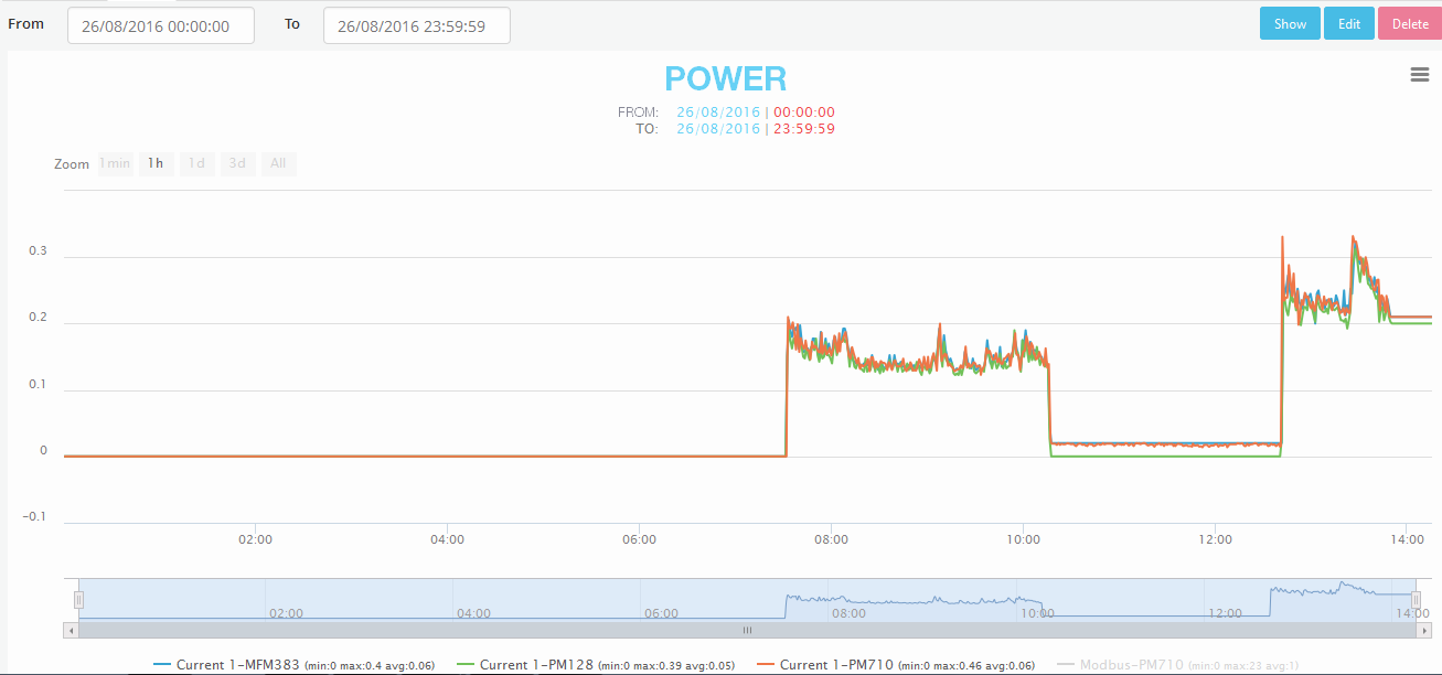
Click on name of parameter (below report) to temporarily ON/OFF parameter on report
6.2.4 Export report
After click button Show to view report, click on top right corner of screen, select Export to Excel or Export to pdf or Export to csv
Click Export to Excel, select version of Excel (2003 or 2007), click Export. The exported file will be store on your PC
Click Export to csv, select version Date Format in csv file, click OK. The exported file will be store on your PC
Click Export to pdf, the exported file will be store on your PC
6.3 Alarm Management
In Home page, select menu Management → select sub-menu Alarm Management to display details of alarm of Device.
6.3.1 Alarm Summary
In screen of Alarm Management, click tab Summary: to view active alarm.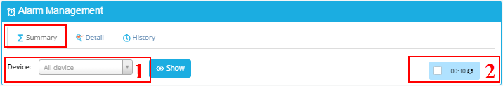
(1) Select Device to view Alarm:
After select Device, click button “Show” to view all active alarm of selected Device.
After click “Show”, screen of active alarm should appear: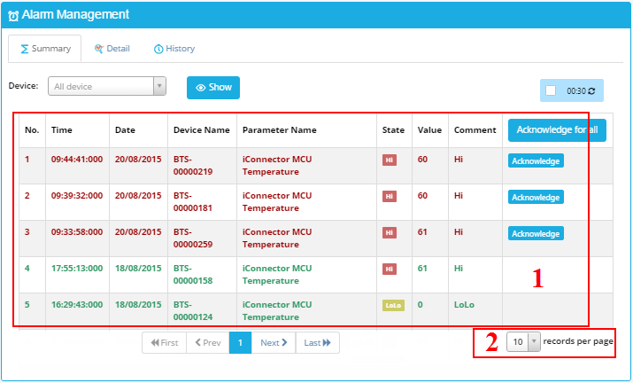
(1) Display alarm of selected Device:
Time: time when alarm occurs.
Date: date when alarm occurs.
Device Name: display name of selected Device.
Parameter Name: display name of parameter which is alarmed.
State: display status of alarm (HiHi, Hi, Lo or LoLo)
Value: display value of parameter when alarm occurs.
Comment: display comment of alarm
(2) Select number of alarm displayed in one page.
6.3.2 Acknowledge Alarm
- Click  to confirm selected Alarm. Confirmation screen should appear:
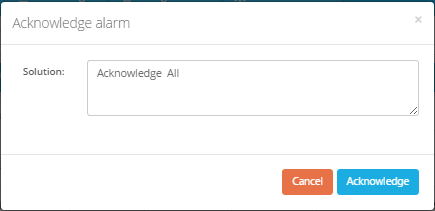
- Enter content of confirmation and then click button “Acknowledge” to save the content.
- After alarm confirmation, red text in alarm row of the list should be changed to green text. Content of confirmation should appear in column “Solution” of tab Alarm History.
6.3.3 Acknowledge all Alarm
- Click  button to acknowledge all displayed Alarm.
6.3.4 Details of Alarm
- In screen of Alarm Management, click tab Detail: to view detail of Alarms: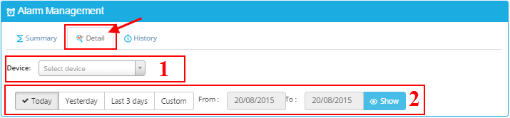 (1) Select Device to view Alarm:
(2) Display period of time to view Alarm:
• Custom: to enter start date and end date to view alarm. Maximum period of time is one month.
• After select Device and period of time, click button “Show” to view Alarm:
6.3.5 Alarm History
- In screen of Alarm Management, click tab History: to view all historical alarms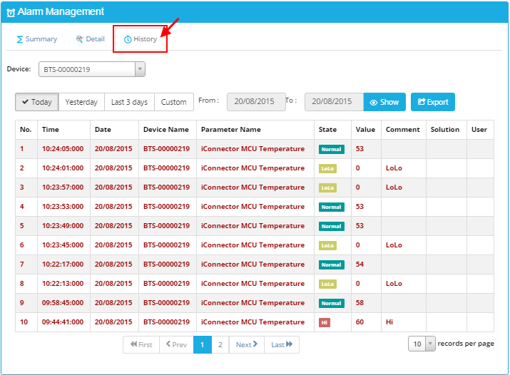
6.3.6 Export Alarms
- In screen of Alarm History, click button to export Alarms to Excel file. Screen of alarm export shoud appear:
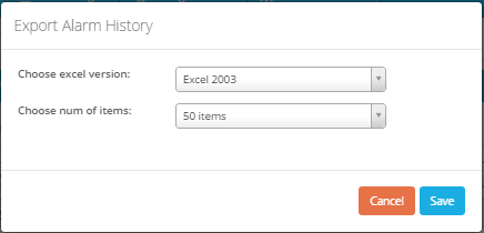
- Choose excel version: select Excel version of exported file: Excel 2003, Excel 2007 or Higher
- Choose number of item: select number of alarm to be exported: 50, 100, 200 Alarms
- Click “Save” to export Alarm list.
- Exported Alarm list should display: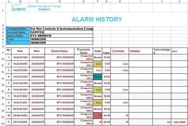
6.4 Event Management
- In Home screen, select menu Management → select sub-menu Event Management: to view historical events.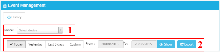
(1) Select Device to view Event:
(2) Period of time to view Event:
• Custom: select start date and end date to view events. Maximum period of time is one month.
• After select Device and period of time, click button “Show” to view Event: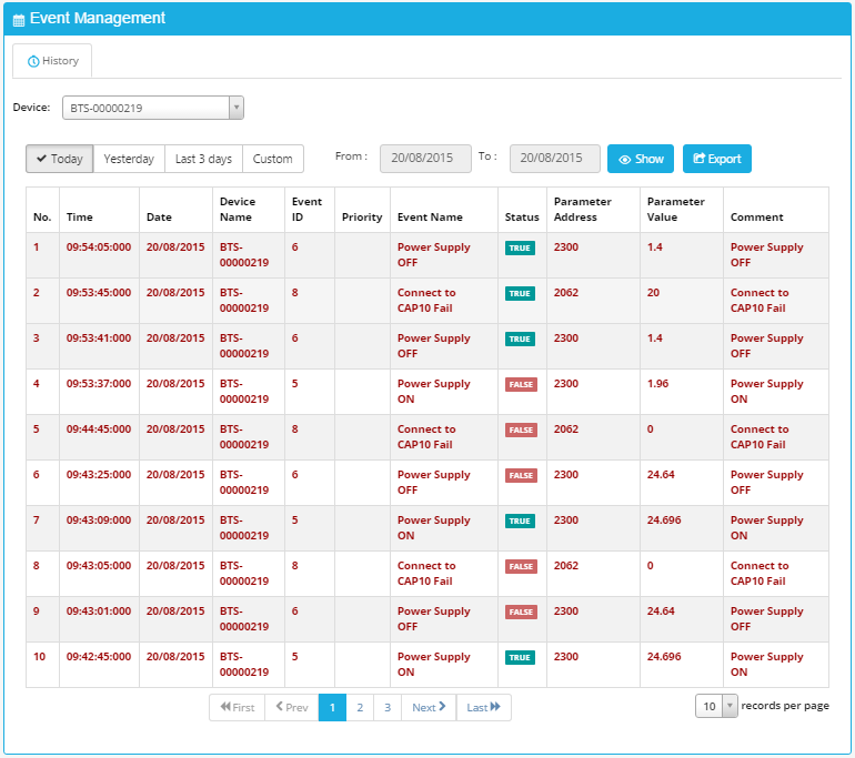
• Button “Export”: Click to export event to Excel file.
• After click button “Export”, screen of event export should appear: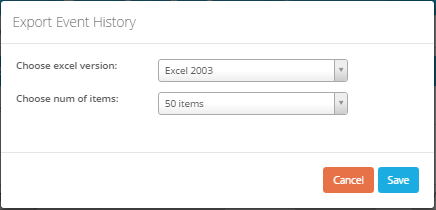
• Choose excel version: select Excel version of export file: Excel 2003, Excel 2007 or Higher
• Choose number of item: select number of Events to export: 50, 100, 200 Events
• Click button “Save” to export event list.
File of exported Events should appear: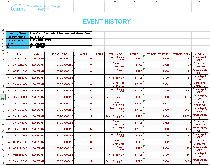
6.5 Import/Export Raw Data
6.5.1 Import
• In menu Management, select Import/Export Raw Data
• Select Import tab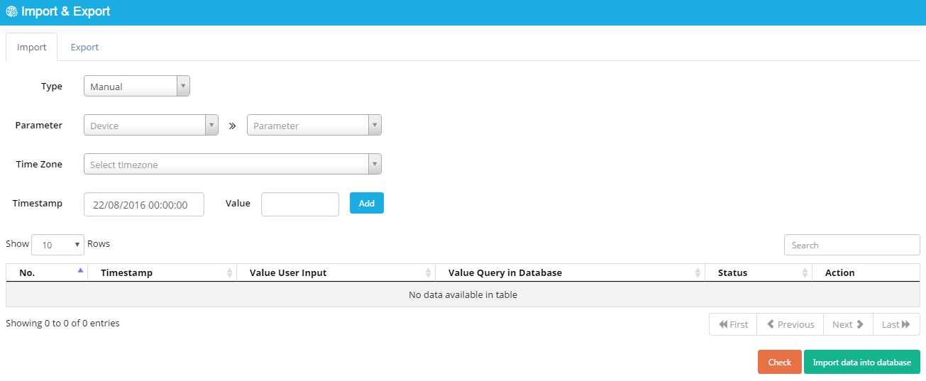
• Type: Manual or file
Manual: data enter from keyboard
File: data load from excel file. Excel should have suitable format
• Parameter: select Device and Parameter
• TimeZone: select time zone
• Timestamp: select time stamp of data
• Value: value of data
• Add: after enter full information, click “Add” to add value of parameter at specific time into list below
Click Check to show table to know input value and value on database
Click Import data into database to import value of parameter into
database. If old data are available on database, user should confirm override
old data
6.5.2 Export
- In menu Management, select Import/Export Raw Data
- Select Export tab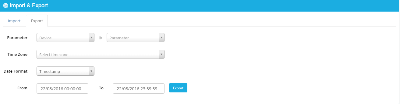
• Parameter: select Device and Parameter
• TimeZone: select time zone
• Data format: select Data format for export time
• From …To: Duration of time to export
Click “Export” to export value of parameter to csv file
6.6 Configure Schedule to Email Report
From menu Management, click sub-menu Schedule for Report, click Add button to add schedule for report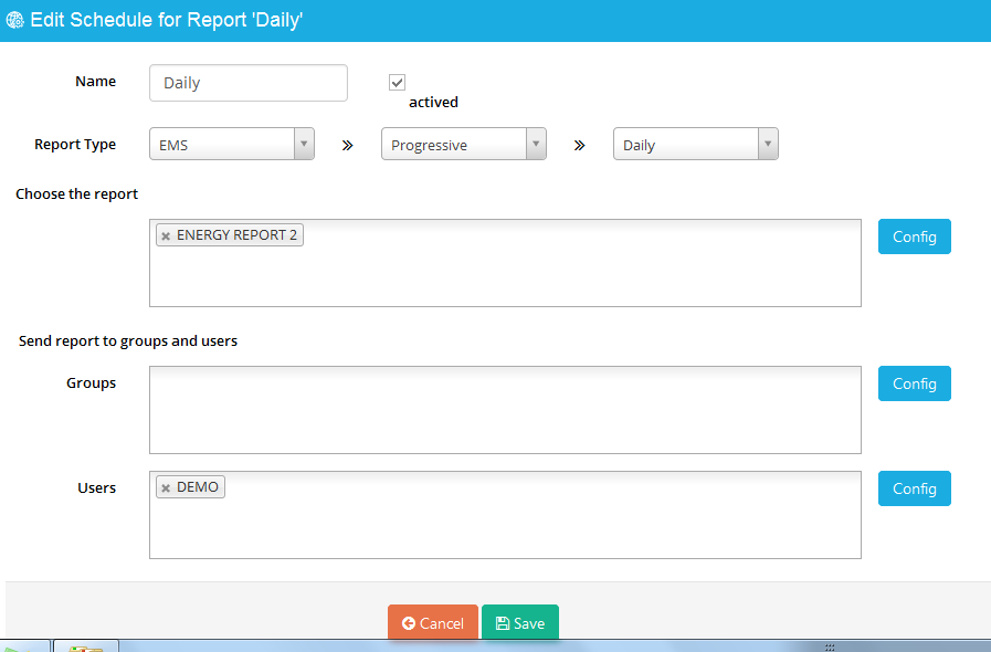
• Name: Name of schedule
• Actived: Tick to active schedule
• Report type: Select type of report. There are 2 types of report available (CNC and EMS). Frequency of sending report depend on report type (daily, weekly, monthly).
• Choose Report: click inside box or click Config to choose report to email
• Send report to group or user: click inside box or click Config to choose group and user who receive email.
• Time to send report is begin time of days which is configured in Account
Note: Email of user must be verified before configuring schedule to email report. Refer 2.1.3 Verify Email for more details
7. Configuration
7.1 Package Configuration
In menu Configuration, select package configuration. The List of Packages displays as follow: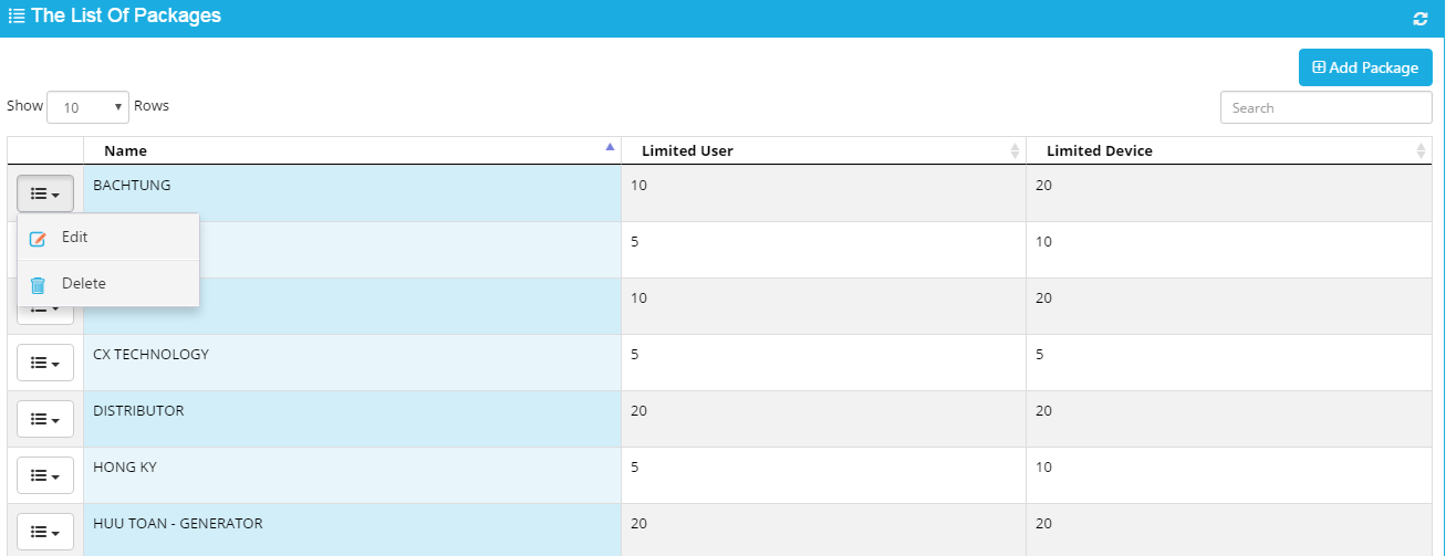
- Click “Add package” to add new Package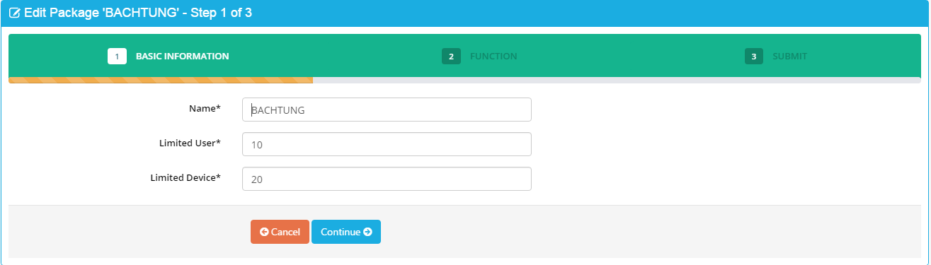
• Step 1: Enter basic information and click continue to next step
• Step 2: Select functions for package
In Permission, select appropriate authorities and click continue to next step
• Step 3: View information of configuration and click “save changes” to finish
- Click “Edit” to Edit available Package
- Click “Delete” to Delete Package
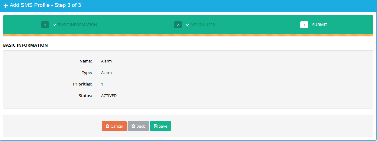
7.2 SMS configuration
Configure SMS for sending SMS when Alarm or Event occur.
Click tab Configuration SMS Configuration Click “Add SMS Profile” button to configure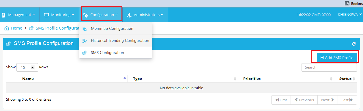
Please do 3 steps follow guide: 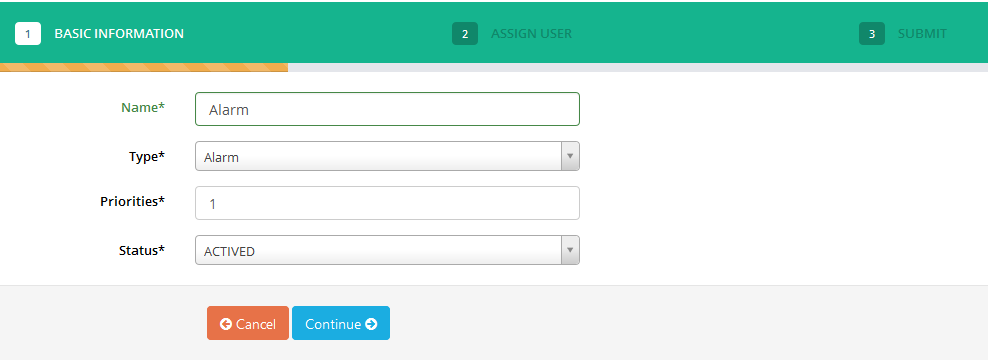
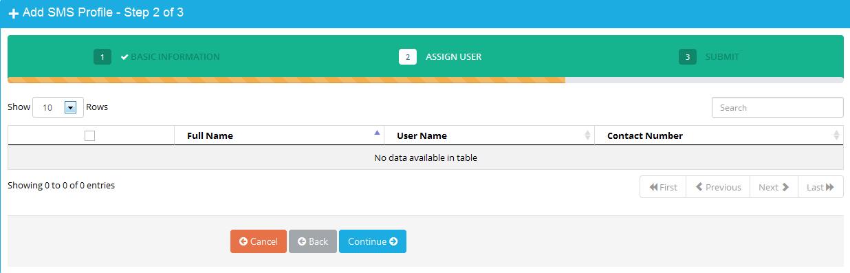
Note: Contact number must be verified before implement SMS configuration. Refer 3.4 Verify Contact Number for more details
8. Administrators
8.1 Account Management
- Account might have sub-account to manage and assign authorities.
- In Home screen, select menu Administrators → select sub-menu Account Management
- In screen of account list, click button “Add account” to create new account.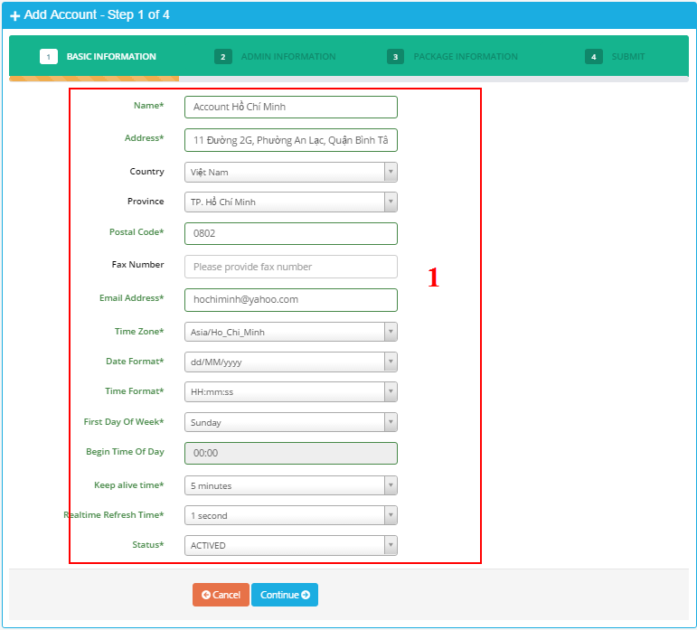
Enter information account into panel (1).
Email: enter email address. Email is unique.
Click button “Continue” to go to step 2.
- Field with mark * must be filled
- In email adress, uppercase and lowercase are the same.
- Select right Time Zone for user.
- After click button “Continue”, screen of step 2 should appear:
Enter information of admin user into panel (1):
• Username: Enter username. Username is unique.
• Email: Enter email address. Email is unique.
• Contact Number: Enter phone number. Phone number is unique.
• Click button “Continue” to go to step 3.
- Screen of step 3 should appear: 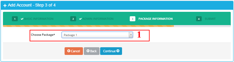
(1) Select package for account.
Click button “Continue” to go to step 4.
- Screen of step 4 should appear:
(1) Display basic information of account in step 1.
(2) Display information of admin user in step 2.
(3) Display assigned package information in step 3.
Click button “Save” to save configuration.
After click button “Save”, confirmation screen should appear: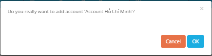
Click “OK” to finish.
- After successfully create new account, an admin user of account is also created.
- Number of used user of account increases by one for admin user.
- Information of admin user should be in user list.
8.2 User Management
User is created by following steps:
- In Home screen, click menu Administrators → select sub-menu User Management
- In screen of user list, click button “Add user” to add new user.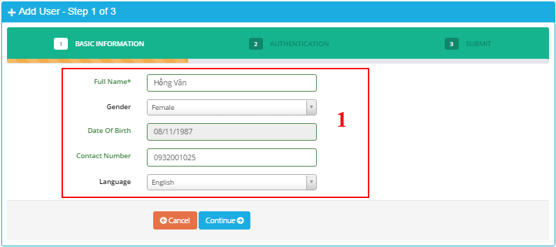
Enter basic information into panel (1).
• Contact Number: Enter contact number. The number is unique.
• Click button “Continue” to go to step 2.
- After click button “Continue”, screen of step 2 should appear: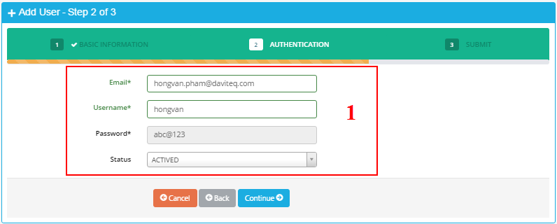
Enter information for user to sign-in into panel (1):
• Email: enter email address. Email is unique.
• Username: enter username for sign in. Username is unique. Username has at least 6 characters.
• Password: default password is “abc@123”. User must change password when user sign in in the first time.
• Click button “Continue” to go to step 3.
- Enter full information for user.
- Uppercase and lowercase of email and username are the same.
Example: username “USERNAME1” is the same as username “username1”.
- Screen of step 3 should appear:
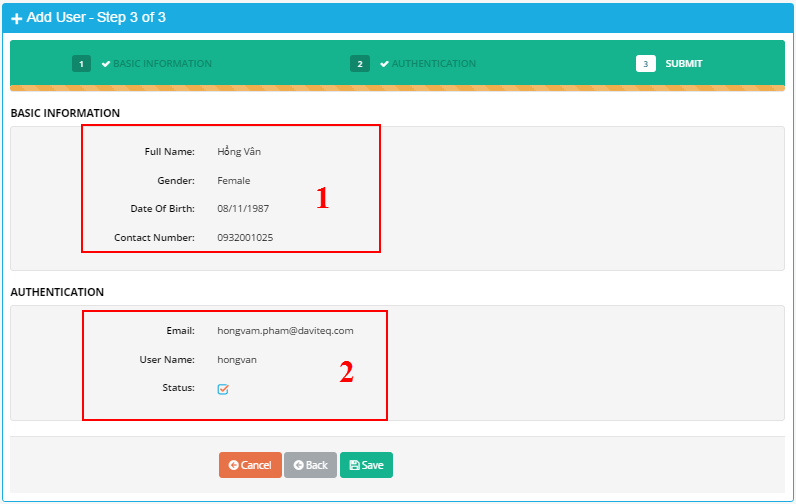
(1) Display basic information of user in step 1.
(2) Display information for sign in in step 2.
Click button “Save” to save information.
After click button “Save”, confirmation screen should appear: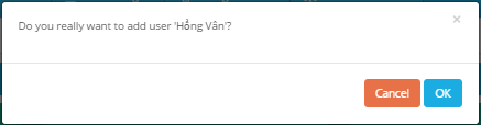
Click button “OK” to finish.
- If number of unused user of account > 0, user will be created successfully. Number of used user should increase by 1.
- If number of unused user of account is equal to 0, user will not be created successfully.
Screen of notification should appear when number of unused user of account is equal to 0: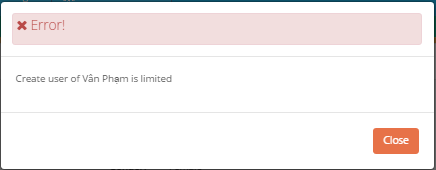
8.3 Group Management
- Group is used to assign authorities to users.
- In Home screen, select menu Administrators → select sub-menu Group Management
- In screen of group list, click button “Add Group” to create new group of account.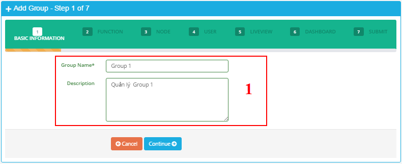
Enter basic information of group into panel (1).
• Group Name: Enter group name. Group name is unique.
• Click button “Continue” to go to step 2.
- After click button “Continue”, screen of step 2 should appear: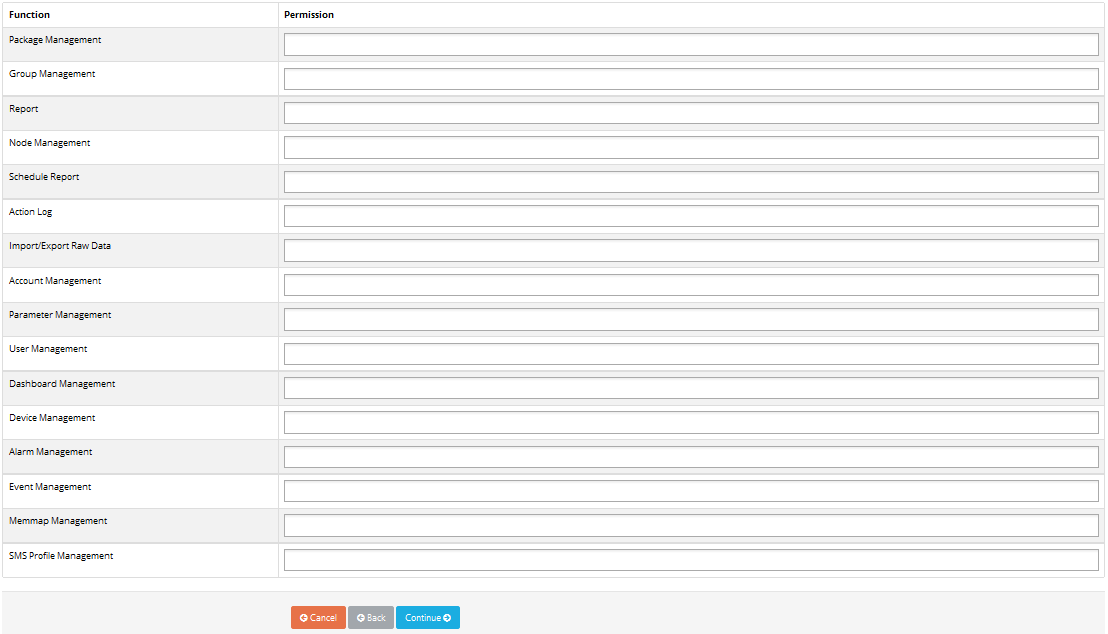
• Select assigned functions for group in area
• Only display assigned functions of account.
• Select one function to assign, then click into area (1) to display authorities of selected function. Click authority to add into group.
• Click mark “x” (2) to remove authority.
• Click button “Continue” to go to step 3.
- Screen of step 3 should appear: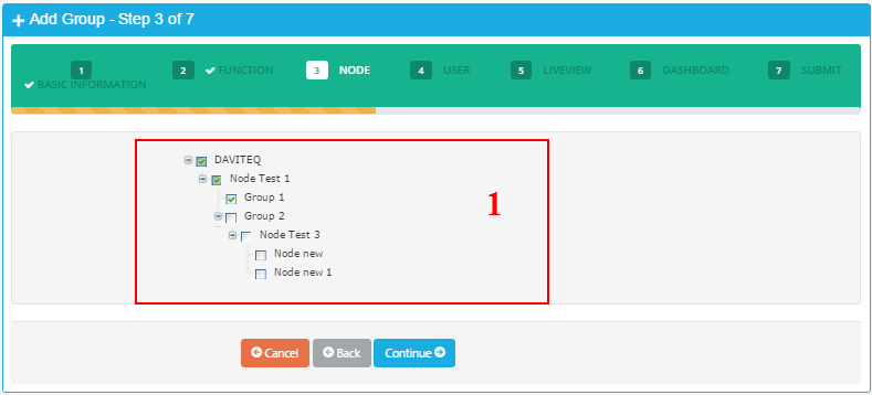
• (1) Display available nodes of account. Tick nodes to assign to group.
• Click button “Continue” to go to step 4.
- Screen of step 4 should appear: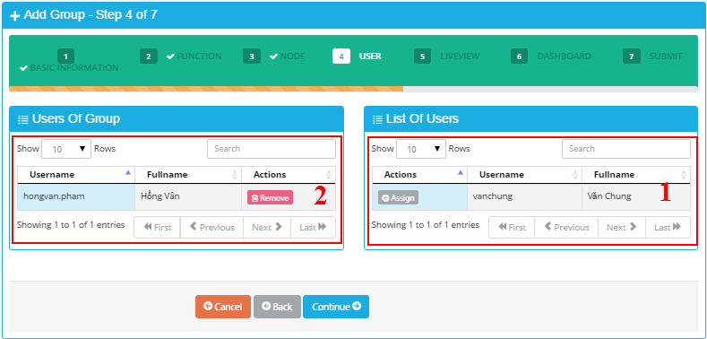
• (1)Display list of users. The users have not been assigned to the group.
• (2) Display list of users which has already been assigned to the group.
• Button “Assign”: click to assign selected user to group. After click “Assign” button, selected user should be in the list in panel (2).
• Button “Remove”: remove user from group. After click button “Remove”, selected user should be in the list in panel (1).
• Click button “Continue” to go to step 5.
- Screen of step 5 should appear: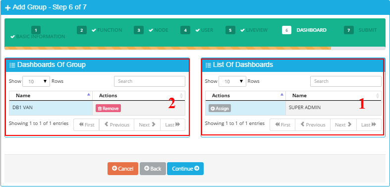
• (1) Display list of Dashboard of signing in group. The Dashboard has not been assigned to group.
• (2) Display list of Dashboard of signing in group. The Dashboard has already been assigned to group.
• Button “Assign”: click to assign dashboard to group. Assigned dashboard should be in panel (2).
• Button “Remove”: remove dashboard out of group. Removed dashboard should appear in panel (1).
• Click button “Continue” to go to step 6.
- Screen of step 6 should appear to view Summary information of group from step 1 to step 8.
• Click button “Save” to save information.
• After click button “Save”, confirmation screen should appear:
• Click button “OK” to finish.
9. Support contacts
|
Distributor in Malaysia
AVO Technology Sdn. Bhd. Official Website: www.avo.com.my No. 17, Jalan 3/23A, Taman Danau Kota, 53300 Kuala Lumpur, Wilayah Persekutuan Kuala Lumpur, Malaysia General : +603-4143 2288 Mobile : +012-376 7181 |
Distributor in Australia and New Zealand
Templogger Pty Ltd Tel: 1800 LOGGER Email: contact@templogger.net |
|
Manufacturer
Dai Viet Controls & Instrumentation Company Ltd. Email: info@daviteq.com | www.daviteq.com |
|

No Comments