Miniature PID Gas Sensor
Features
-
Patented ‘fence’ electrode for excellent humidity resistance (from iOnScience)
-
Anti-contamination design
-
Reliable lamp ignition – illuminates at low temperatures
-
Superior lamp life – 10.6 and 10.0 eV => 10,000 hours
-
User-replaceable electrode stack in event of corrosive or mechanical damage
-
Lamp out error detection (for Range 0-4000 PPM only)
Applications
-
Industrial hygiene & safety monitoring
-
Soil contamination and remediation
-
Hazmat sites and spills
-
Leak detection
-
EPA Method 21 and emissions monitoring
-
Arson investigation
-
Indoor air quality monitoring
-
Outdoor air quality monitoring
1. Selectable Ranges (Isobutylene equivalent) & Performances:
- Range: >10,000 ppm. Minimum detection limit: 500 ppb (10.6 eV Lamp). Response time in diffusion mode (T90) < 3s
- Range: 0 to 4000 ppm. Minimum detection limit: 100 ppb (10.6 eV Lamp). Response time in diffusion mode (T90) < 3s
- Range: >200 ppm. Minimum detection limit: 20 ppb (10.6 eV Lamp). Response time in diffusion mode (T90) < 8s
- Range: 0 to >100 ppm. Minimum detection limit: 5 ppb (10.0 eV Lamp). Response time in diffusion mode (T90) < 8s
- Range: 0 to >100 ppm. Minimum detection limit: 100 ppb (11.7 eV Lamp). Response time in diffusion mode (T90) < 8s
- Range: 0 to >40 ppm. Minimum detection limit: 1 ppb (10.6 eV Lamp). Response time in diffusion mode (T90) < 8s
- Range: 0 to 3 ppm. Minimum detection limit: 0.5 ppb (10.6 eV Lamp). Response time in diffusion mode (T90) < 12s
Environment:
- Relative humidity range: 0 - 99% RH, non-condensing;
- Operating Temp Range: -40 °C to +55 °C ( except 0 - 40 °C for Range 3PPM sensor)
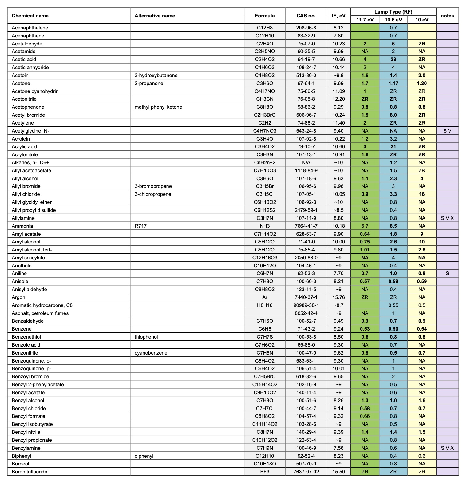
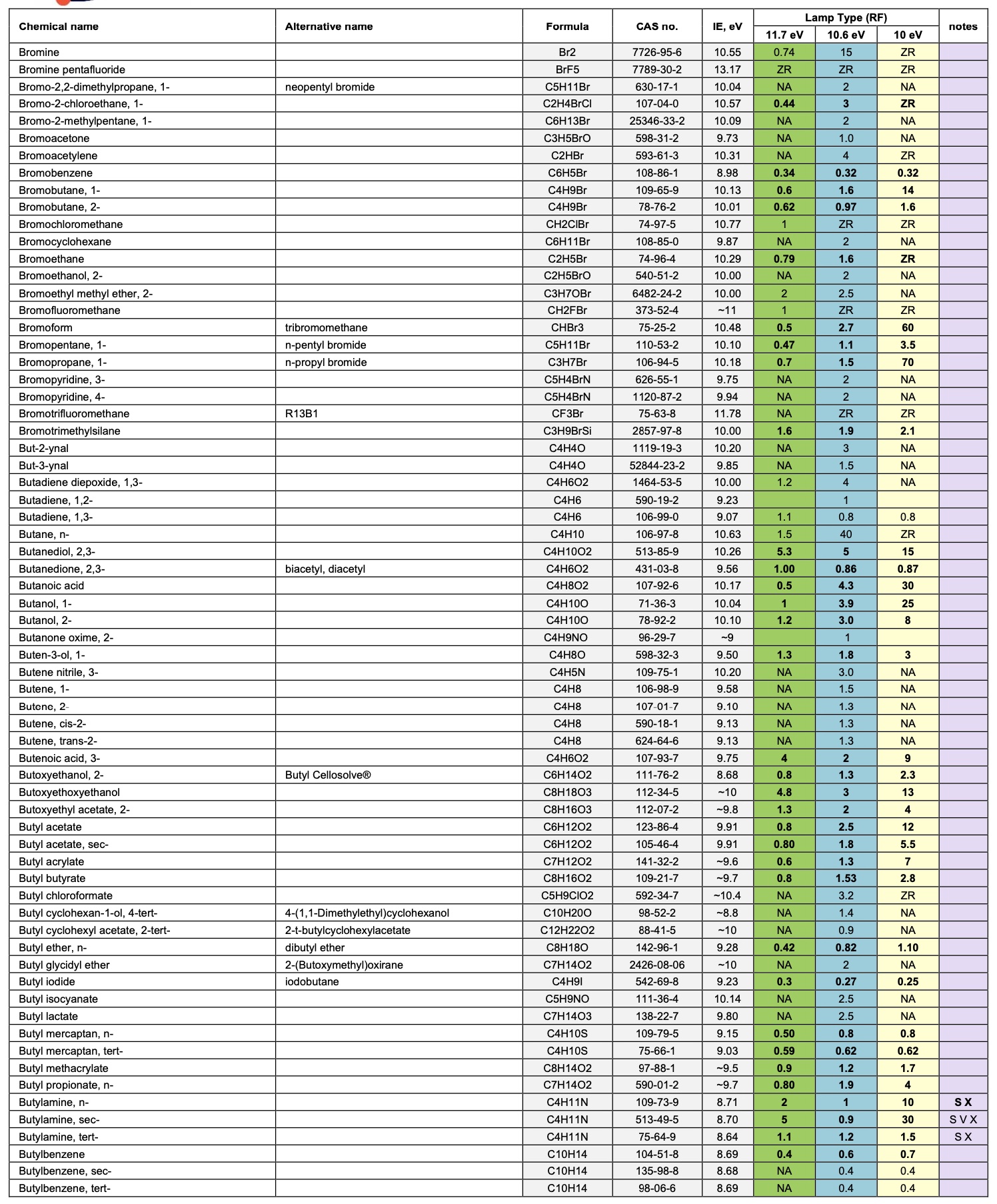
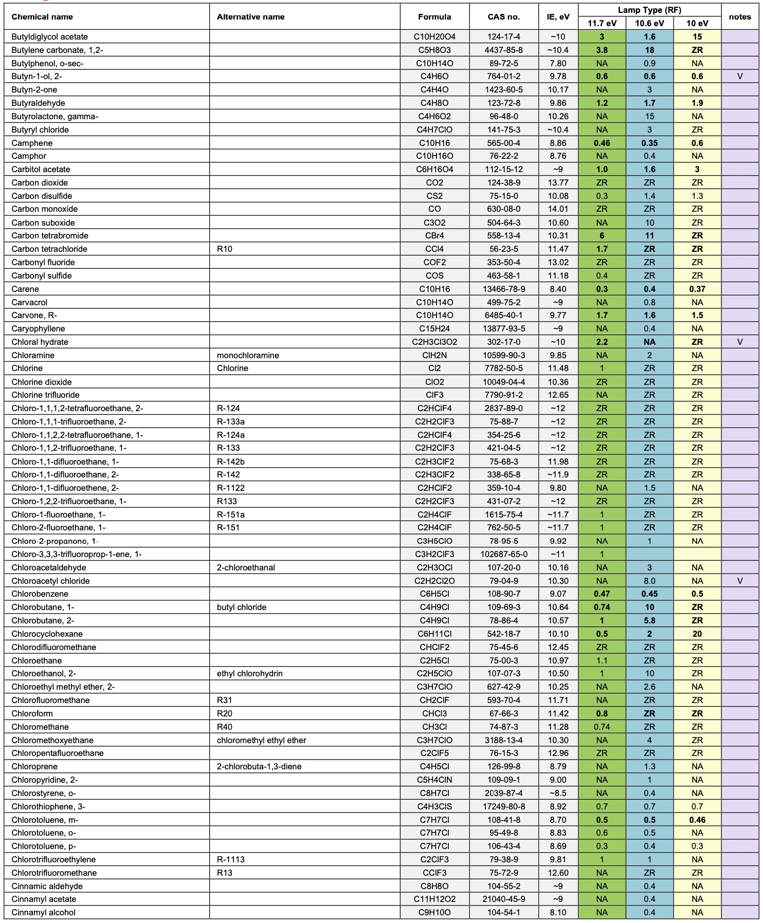
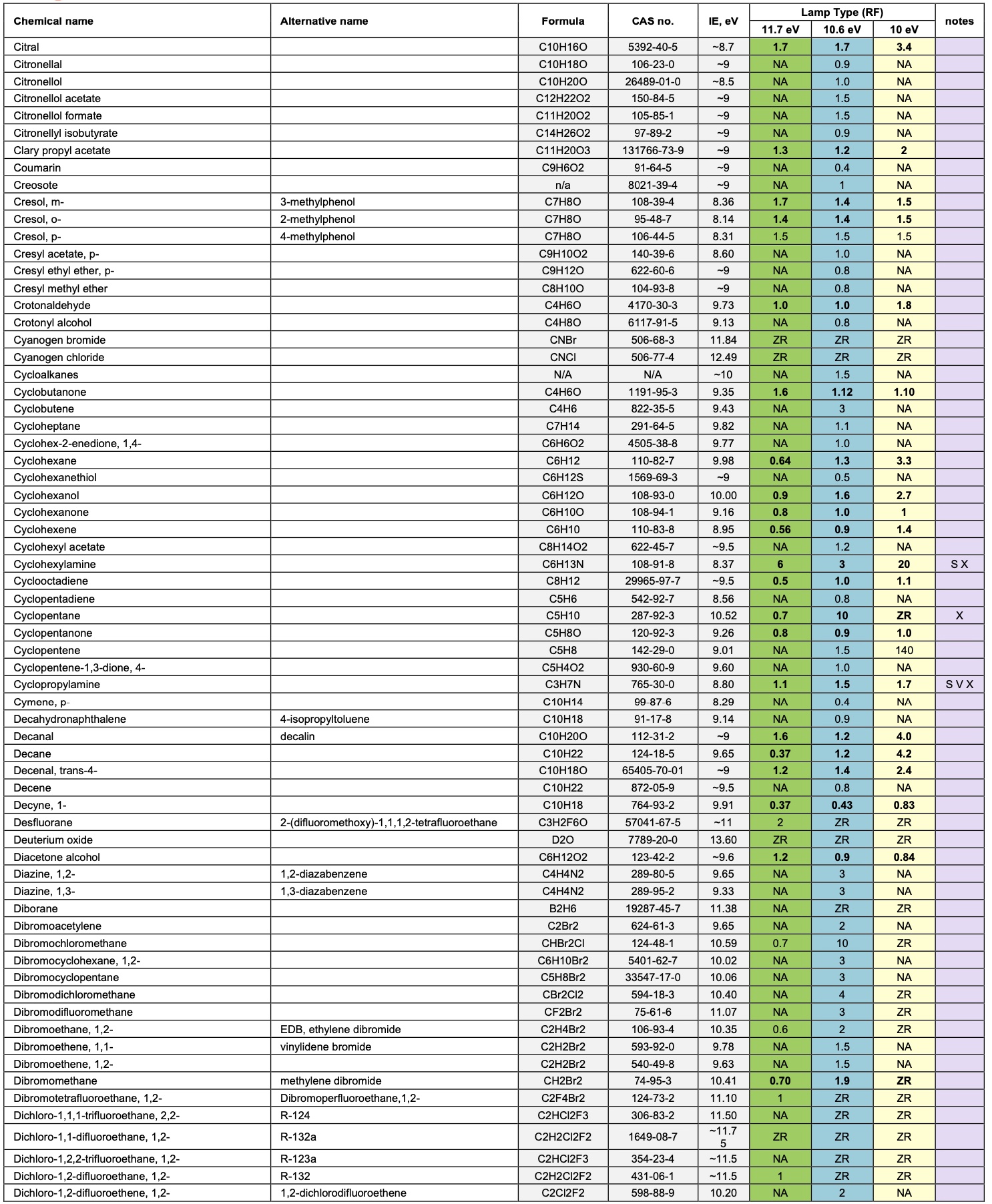
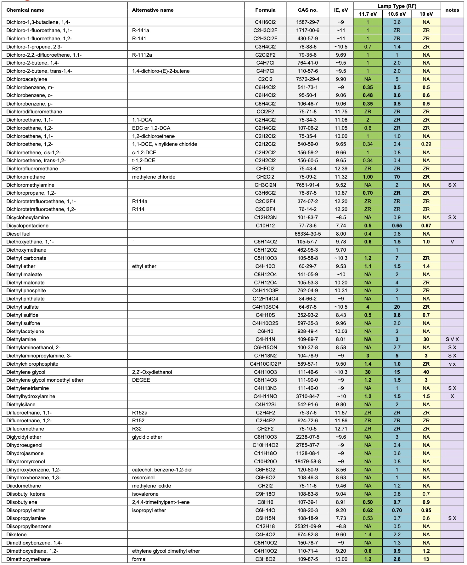
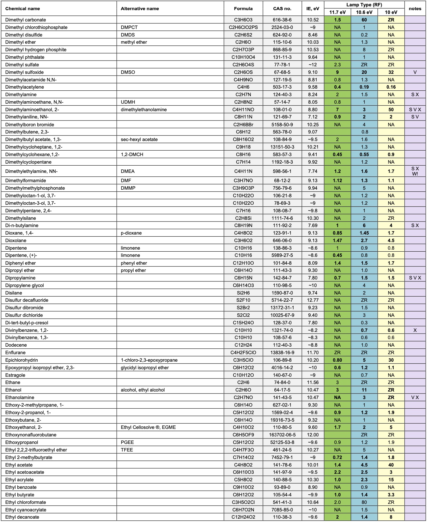
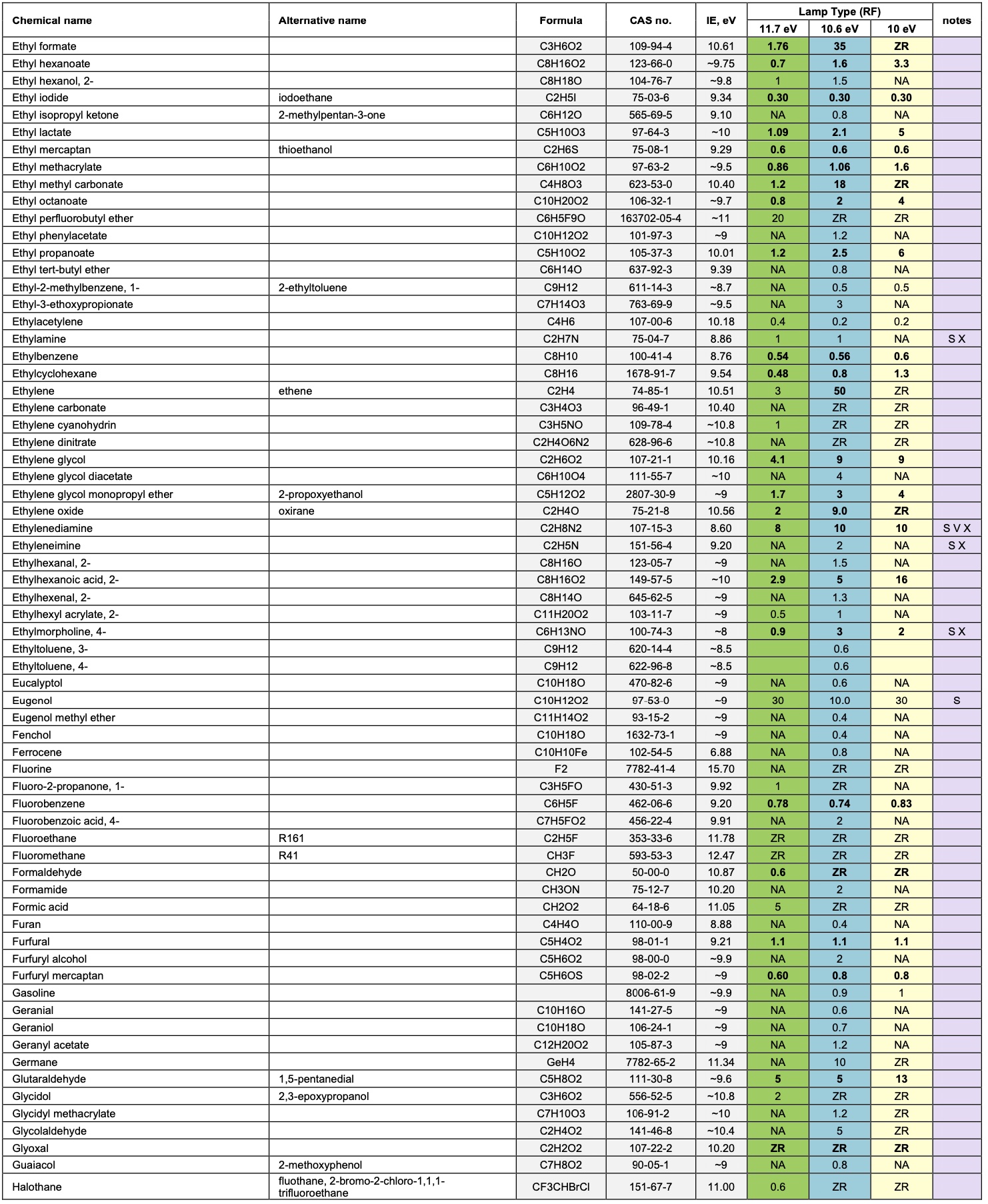
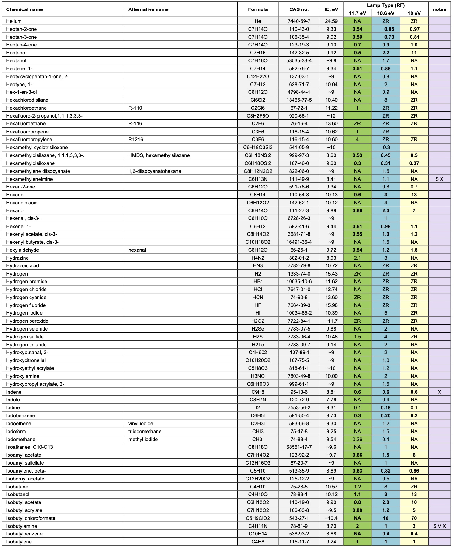
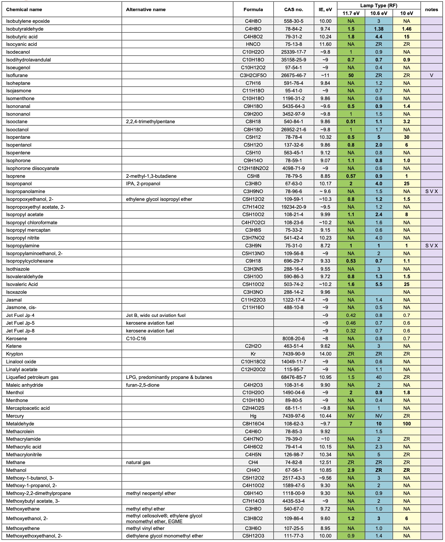
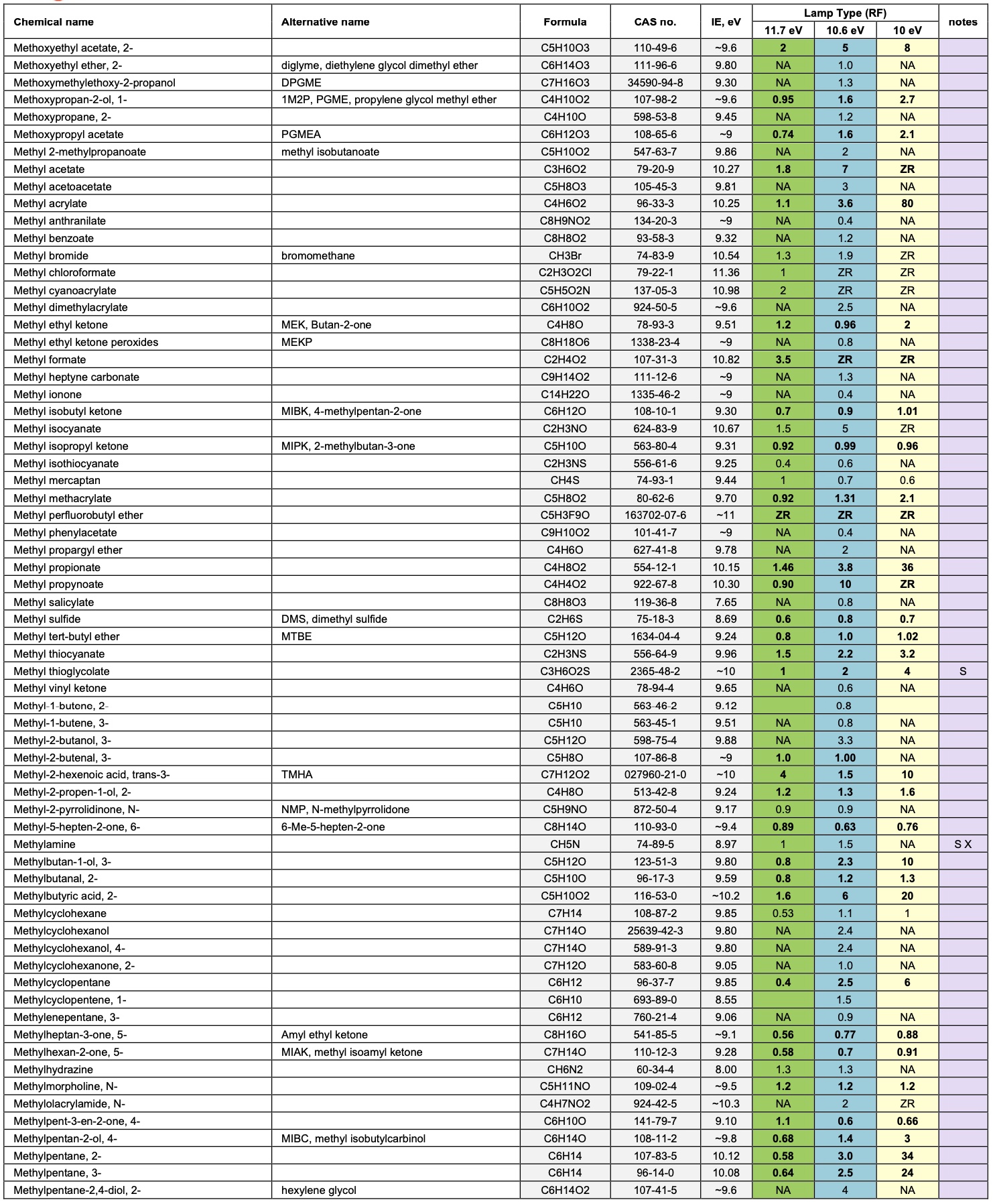
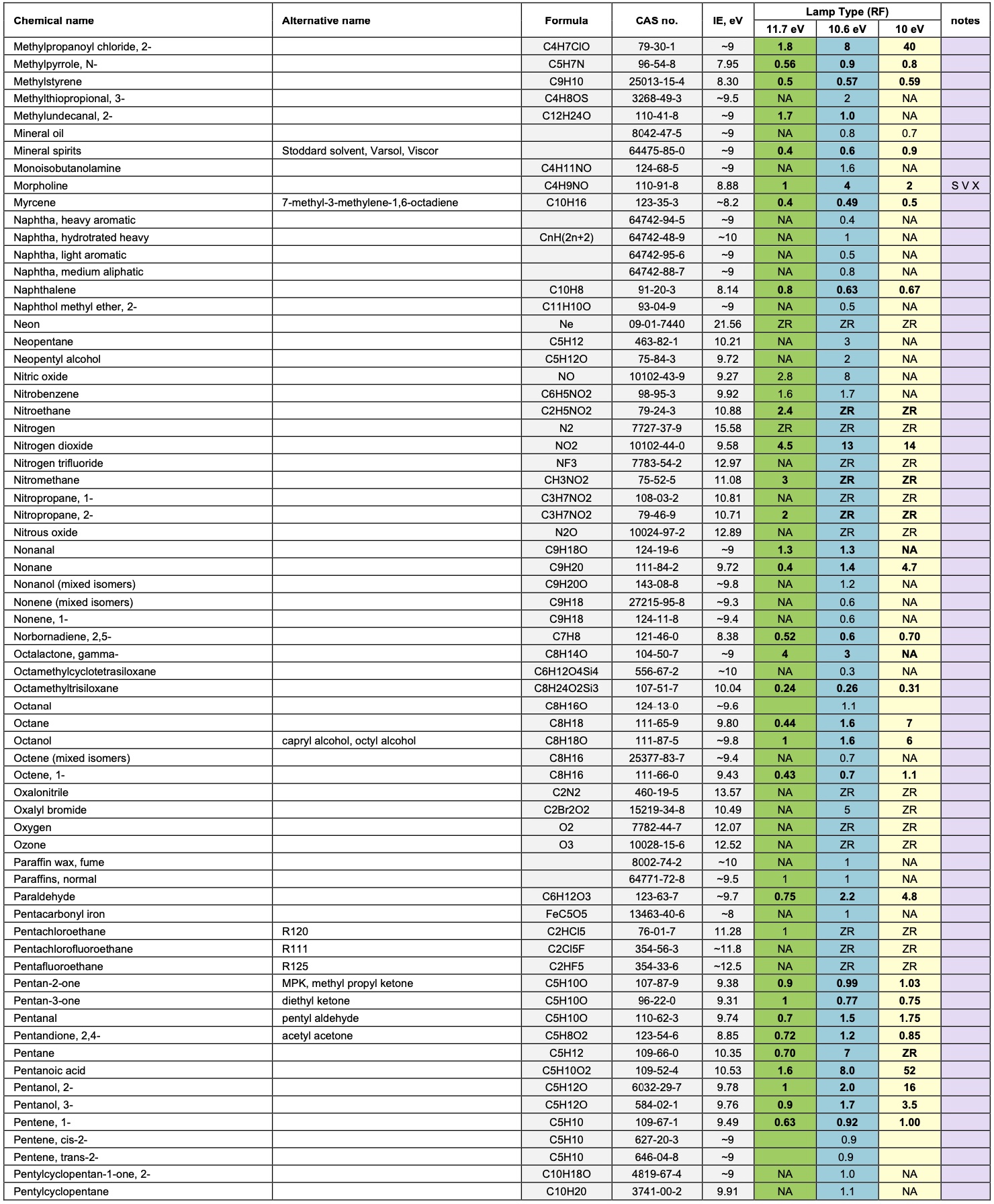
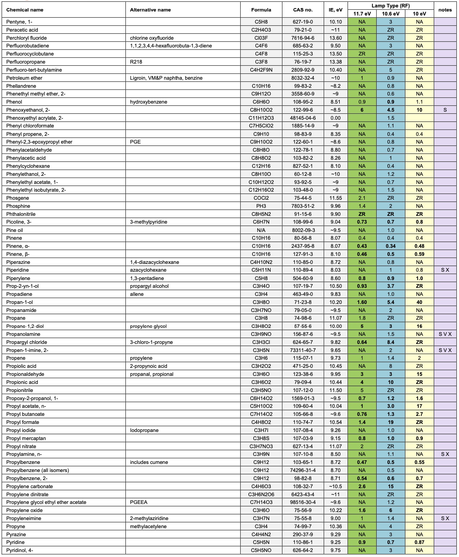
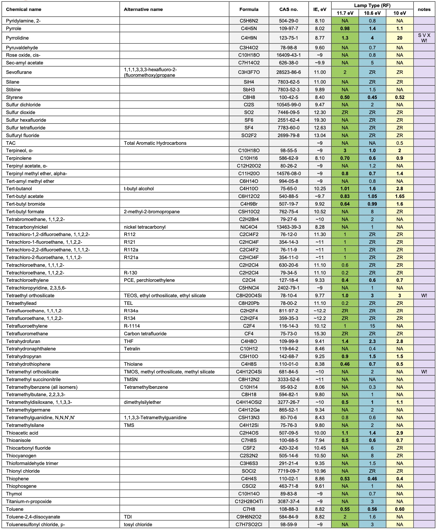
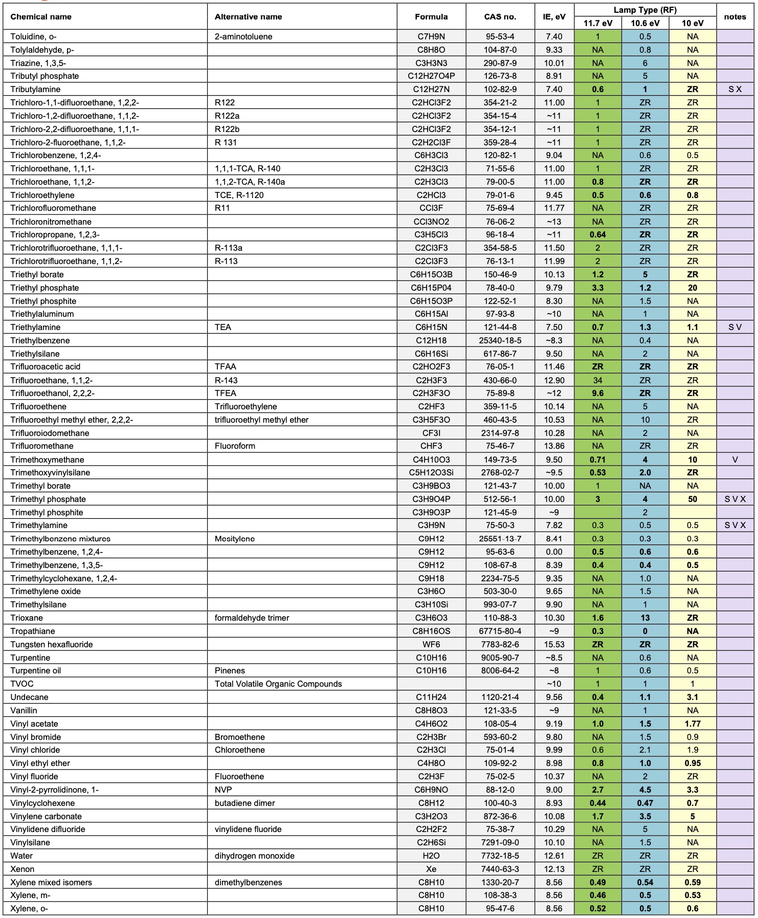
2. Response Factors for other Gases:
Our PIDs are calibrated using isobutylene, but PID is a broadband detection method with a variable sensitivity to each VOC. The relative sensitivity to each compound also varies significantly with PID photon energy (10, 10.6 or 11.7 eV). It varies much less with PID design and lamp output.
Response Factors (RFs) provide an indication of the relative sensitivity of PID to specific VOCs, relative to isobutylene. The RF of a VOC is used to convert the calibrated response of the sensor with isobutylene into a concentration of the target VOC.
Example: Toluene
-
A PID 10.6 eV sensor is calibrated with isobutylene and found to have a sensitivity of 1 mV ppm-1.
-
If the sensor is exposed to 100 ppm isobutylene the output will be 100 mV.
-
The response factor for toluene using 10.6 eV is listed as 0.56.
-
If the sensor is exposed to 56 ppm toluene then the displayed uncorrected concentration will be 100 ppm
isobutylene. The corrected concentration would be 100 multiplied by the RF, 0.56, which gives the correct result of 56ppm toluene.
A complete list of response factors is shown below.
If response factors are programmed into an instrument, it is possible for target VOC to be specified, and the instrument can then display and record a concentration for that target volatile.
The Notes column below identifies the following:
S: slow. PID requires at least 30 s for a stable response.
V: Variable response. The response is susceptible to small changes in ambient conditions, particularly humidity.
X: Temporarily contaminating. PID responsivity may be suppressed for at least 30 min after 100 ppm-min exposure.
W!: Expected to cause PID lamp window fouling. May require regular bump tests and window cleaning.

Calculating the sensor responsivity to VOC mixtures
A volatile organic compound, or VOC, is a carbon-containing chemical, which is significantly or completely vaporised at ambient temperatures.
Occasionally you will be measuring a mixture of VOCs. If the total concentration is within the linear range of the PID, then it is reasonable to assume that the concentrations are additive without interference between the different VOCs:
The correction factor for a gas mix containing PID detectable gases A, B, C... with response factors RF(A), RF(B), RF(C), in fractional proportions a:b:c is given by:
RF mix = 1/[a/RF(A) + b/RF(B) + c/RF(C)...]
Example: A gas mix to be monitored contains 1 part isopropanol to 4 parts acetone:
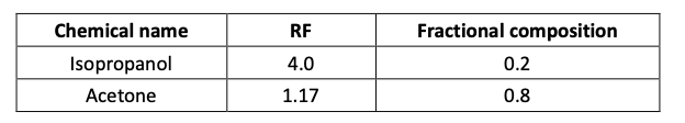
Therefore the RF of the mix will be:
RF mix = 1/[(4.0 x 0.2) + (1.17 x 0.8)] = 1/(0.8 + 0.936) = 0.58
Important: remember that if you are measuring a combination of VOCs then accurate measurement of one of these VOCs will be difficult; without careful data analysis you will get only a RF averaged measurement. Also, note that in the volatilisation of mixtures of VOC’s of different volatility, the more volatile fraction volatilises most rapidly, and the least volatile most slowly, leading to a change in the composition of the liquid and vapour mix.
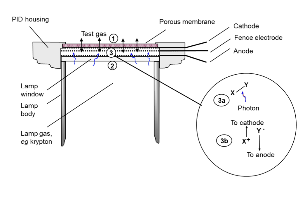
How PID Sensor works?
The PID sensor measures volatile organic compounds (VOCs) in air by photoionisation detection (PID). The sensing mechanism is shown schematically below. Test gas (1) is presented to the external face of a porous membrane, through which it freely diffuses, into and out of a gaseous enclosure, (shown by double headed arrows). From the opposite face of the enclosure, (2) an illuminated lamp emits photons of high energy UV light, transmitted through a crystal lamp window (wavy arrows). Photoionisation occurs in the enclosure when a photon collides with a photoionisable molecule (3a) to generate two electrically charged fragments or ions, one positively charged, X+, and one negatively charged, Y- (3b). These are separated at, oppositely charged metal electrodes, being a cathode and anode, generating a tiny electric current. The current is amplified in an electric circuit (not shown) and presented as a sensor voltage output which depends on the concentration of photoionisable gas. The MiniPID 2 includes a third fence electrode which ensures that the amplified current does not include significant contributions due to other current sources such as electrolytic salt films on the chamber walls.
Volatile organic compounds (VOCs) sensed by PID sensor
Most VOCs can be detected by PID sensor. Notable exceptions are low molecular weight hydrocarbons.
Every VOC is characterised by an Ionisation Energy (IE). This is the minimum energy required to break the VOC into charged fragments or ions. Volatiles and gases in air are photo-ionised, and hence detected, when exposed to light of photon energy greater than their IE. PID sensor is provided with a light source of three different photon energies: 10.0 eV, 10.6 eV or 11.7 eV.
Standard PID sensors (PPM, PPB and HS) engage an unfiltered krypton light source, which delivers 10.6 eV UV light. The sensors respond to about 95% of volatiles, notable exceptions being most volatiles of one carbon atom, acetylene, ethane, propane and saturated (H)CFC’s
The PID 11.7 eV, which employs an argon lamp light source, responds to almost all VOCs: the few exceptions are methane, ethane and saturated fluorocarbons. 11.7 eV PID is less selective but particularly of interest in measuring formaldehyde, methanol and the lighter hydrocarbons, for which scant other sensing technology is available.
Finally, PID 10.0 eV, which engages a krypton light source and a crystal filter, responds to more limited range of VOC’s. Aromatics and most other unsaturated molecules are most readily detectable with this lamp, whereas most saturated hydrocarbons, with which they often occur, are sensed more weakly or not at all.
For detection of a volatile compound, it must be sufficiently volatile. A fairly large molecule such as alpha-pinene, (a constituent of turpentine), saturates in air at about 5000 ppm at 20 oC; this is the maximum concentration of the alpha-pinene that can be measured at 20 oC. Some compounds, e.g. machine oils and plasticisers, generate a fraction of a ppm of vapor at ambient temperatures. Because the diffusion of such large molecules is also very slow, in most scenarios they are not detectable. Organic compounds of boiling points 275 to 300 oC (at 1 atm.) are considered to be semi-volatiles and marginally detectable. Compounds of boiling point > 300 oC are considered non-volatile and undetectable.
Installation Notes
-
If the PID is deployed in a wall mountable detector, the sensor is ideally located in the instrument to be as far from the wall mountings as possible, to minimise condensation phenomena caused by the air vs wall temperature disparity (consider the accumulation of particulates and heavy volatiles on shelves and kitchen units).
-
The sensor should be pointing downwards or sideways, to avoid slow accumulation of volatile in the sensor cavity, and dust.
Error States
| Sensor Types |
Fault Condition
|
Recommended Action |
|
| 0-4000 ppm Sensor | All others | ||
| Error 4 | N/A |
Lamp not illuminated |
Change or clean lamp |
| Electrode stack not fitted correctly |
Ensure electrode stack is fitted correctly |
||
| Error 3 | Error 3 |
Oscillator not working |
Change the PID |
|
Misplaced electrode stack |
Change electrode stack |
||
| Error 2 | Error 2 |
Oscillator overloaded |
Change electrode stack and/or PID |
| Error 1 | Error 1 |
Power removed |
Consult manufacturer |
Calibration Guidelines
PID sensor naturally produces ozone in air, which over time acts to remove organic detritus from within the PID cavity. In many domestic and light industrial environments, the PID is self-cleaning. Re-calibration is then only needed to adjust for any decay in the PID lamp output on which the photoionisation measurement depends. In a fixed instrument, typically this will be every one to two months of cumulative sensor operation. However, when first deploying a PID instrument in a new environment, end users should be encouraged to bump test and re-calibrate as necessary. Since portable PID instruments are exposed to unknown environments, their calibration may be required more often.
Calibration of instruments containing PID usually demand measurements of ‘zero gas’, containing near zero concentrations of VOCs, and a span gas, used to calibrate the PID sensor in its linear range. Both gases are usually prepared with a ‘balance’ gas of artificial air, comprising ~80% nitrogen and ~20% oxygen. Do not use pure nitrogen as a balance gas as this delivers up to 20% more responsivity than air.
Appropriate end user calibration gases for the various MiniPID 2 sensors are identified below:
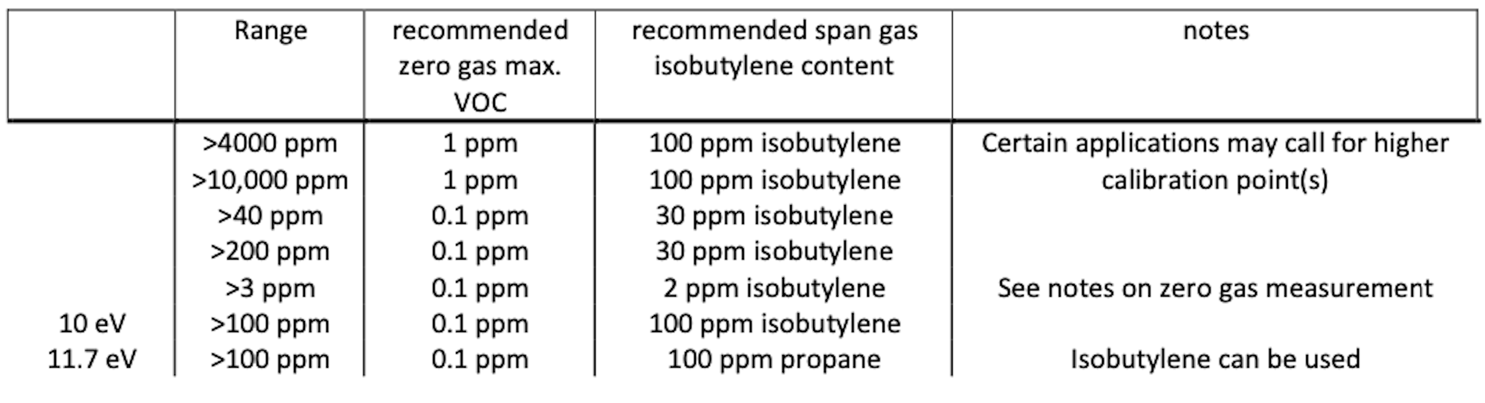
Zero gas of <0.1 ppm VOC is usually provided by ultrahigh purity (UHP) air. To enable frequent calibration, purified gas systems providing the same gas purity can be used. Lubricating oils in compressed air lines should be avoided as they will foul PIDs if exposed to the gas stream for extended times.
Some gases absorb UV light without causing any PID response (e.g. methane, ethane). In ambient atmospheres where these gases are present the measured concentration of target gas will be less than is present. Methane absorbs UV strongly, so for accurate measurements in methane containing atmospheres, calibrate with a calibration gas containing the expected methane concentration.
The HS sensor requires particular care in handling as identified in the technical article TA-14. Since air may contain semi-volatiles which give rise to a significant and slowly moving sensor response, calibration of a high sensitivity VOC detector must always be undertaken after burn-in using clean air. This will provide the zero point calibration reading.
Maintenance
Routine Maintenance
The electronics in the PID sensor are not accessible and designed to be maintenance-free.
The electrode stack is easily replaced and inexpensive. The PID stack will operate for years in most non-corrosive environments. It is recommended that end users of instruments containing PID carry at least one electrode stack in stock. The electrode stack is not toxic. Due procedures should be considered for safe disposal in the event of the stack being exposed to toxic environments.
Unscheduled Maintenance
The PID should be dismantled and stack and lamp inspected in the following circumstances:
-
On exposure of the sensor to very humid, acidic (sour) and salty environments. This may cause inorganic salts to accumulate on PID enclosure walls, which ultimately compromises the screening potential of the PID fence electrode. This is often indicated by a moisture sensitive signal.
-
Visual indications of liquid ingress into the electrode stack.
-
A sensor error 4 indicates a failure of contact has developed between the sensor pins and the stack pads. The wings on the PID stack may fail after repeated dis- and re-assembly. It may also be caused by failure of the stack to engage fully with the sensor body, which may be corrected by refitting the lamp and stack. The PID lamp should be cleaned and replaced as necessary if the responsivity of the sensor, as measured in bump tests or during calibration, decreases unexpectedly. Note that exposure of the sensor to amines is liable to temporarily contaminate the PID lamp. Instrument design should cater for this.
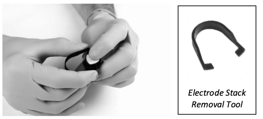
Removing the electrode stack and lamp
CAUTION: Only use the electrode stack removal tool. Any other tools (for example screwdrivers) may damage your PID body and will invalidate your warranty.
-
-
Wear gloves. Carefully remove the sensor from instrumentation.
-
Locate electrode stack removal tool in the side slots of the PID and squeeze together until electrode stack and lamp are released.
-
Lift carefully the PID body away from the electrode stack and lamp.
-
Occasionally the lamp may be temporarily lodged in the sensor body and will need to be freed carefully with tweezers. Occasionally the small spring behind the lamp will come out when the lamp is removed from the sensor. Simply replace it into the sensor body.
-
Inspecting the PID stack
On removal of the electrode stack, carefully inspect the underside. The visible electrodes should be shiny and metallic. If there are any signs of corrosion or water ingress the stack should be replaced.
Inspecting and cleaning the PID
NOTE: Alumina polishing of lamps described below is appropriate for all
PID lamps except the PID 11.7 eV lamp.
Inspection of the PID lamp, as shown in the illustration, may reveal a fine film of contamination on the lamp window. However, it should be noted that window contamination is frequently not visible. Black or metallic deposits on the interior face of the lamp cannot be removed. If the deposits are extensive, the lamp must be replaced.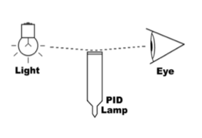
To clean the lamp, use of PID lamp cleaning kit A-31063. Validity of lamp warranty is compromised if lamp cleaning maintenance is not followed and lamp has obvious fouling/contamination.
-
Wear gloves. Never touch the lamp window, even with gloves.
-
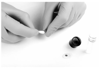
Open the container of alumina polishing compound.
-
With a clean cotton bud, collect a small amount of the powder.
-
Use this cotton bud to polish the PID lamp window. Use a circular action, applying light pressure to clean the lamp window. Do not touch the lamp window with fingers.
-
Continue polishing until an audible “squeaking” is made by the cotton bud moving over the window surface. Usually this requires 15 to 30 s polishing.
-
Remove the residual powder from the lamp window with a clean cotton bud. Care must be taken not to touch the tips of cotton buds that are to be used to clean the lamps.
-
Ensure the lamp is completely dry and all detritus is removed before reassembling the lamp stack and body (see below).
-
Re-assemble the sensor lamp, stack and sensor body as described below, and reinstall sensor in the instrument.
-
Bump test the sensor. If the responsivity has recovered, then recalibrate the instrument. If not, replace the lamp.
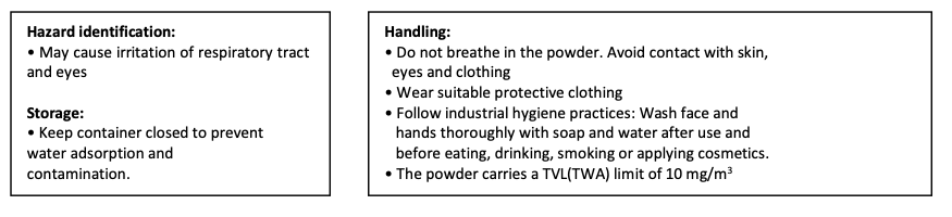
CAUTION: The lamp cleaning kit contains alumina (CAS Number 1344-28-1) as a very fine powder. Cleaning should be undertaken in a well-ventilated area. A full material safety data sheet MSDS is available on request from Ion Science Ltd. Key safety issues are identified below:
Assembly of MiniPID 2 electrode stack, lamp and body.
CAUTION: Do not assemble using a damaged lamp as this may rupture the stack’s lamp O-ring seal.
-
Lay the electrode stack front face down on a clean, flat surface and then screw the lamp down into the O-ring until it firmly abuts against the front electrode face.
-
Place the PID body carefully down over the lamp-stack sub-assembly so as not to disturb its seating within the electrode stack and then push the body firmly onto the face down electrode stack so that both wings engage with the PID body.
-
Inspect the sensor to confirm that both wings of the electrode stack have engaged with the PID body.
-
Refit the sensor into the sensing instrumentation.
-
Re-calibrate the equipment in accordance with manufacturer’s instructions.
Instrument Warranty and Service
Warranty
The standard warranty on a PID is 12 months.
Service and service centers
Daviteq is pleased to offer a number of service options for our PID product range that allows you to choose the cover that best suits your needs.
Contact Daviteq or your local distributor for service options in your area.
No Comments