Daviteq AC 5A Current Transducer - Measurement Principle
1. Overview
Daviteq AC 5A current transducer is a transducer to convert the AC current from the Current Transformer (CT) to DULP digital output so that it can connect to any wireless transmitter of Daviteq.
It can connect to any brand of CT on the market.
2. Detail measurement principle
The AC current from CT will go thru a precision resistor to convert to voltage value in mV, then the electronics circuit will convert the mV signal to digital value via the DULP interface which is read by the wireless transmitter.
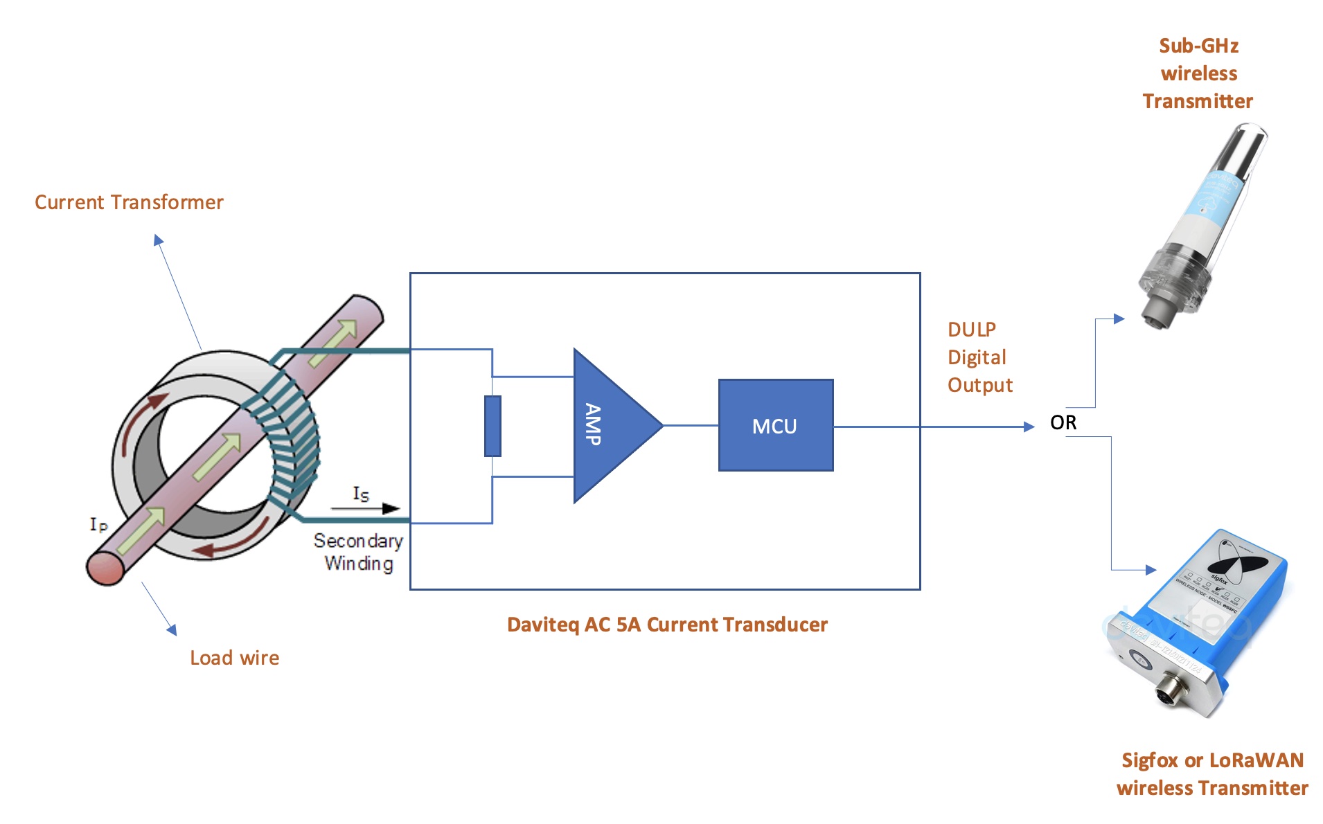
The Daviteq AC current transducer can connect to any Wireless transmitters manufactured by Daviteq which support DULP output.
* DULP: Digital Ultra-low Power

The AC current transducer connects to the Sub-GHz wireless transmitter WS433-AC
The transducer will output the actual current value of the secondary coil of the CT which has max 5A AC. To get the actual load current value, the user needs to configure the CT ratio in the wireless transmitter part.
For example:
* if the CT is 100/5 ==> the CT ratio must be 20;
* if the CT is 600/5 ==> the CT ratio must be 120;
3. Calibration of the Daviteq AC current transducer
The Daviteq AC current transducer is designed and manufactured with accuracy:
+/- 1% of Reading value and +/- 50 ppm of Reading per degree Celcius.
The user can do re-calibrating the transducer by using an AC current calibrator to generate the accurate AC current. The calibration will be done by changing the A & B factors on the wireless transmitter part. Please refer to the manual for the wireless transmitter to know how to change those A & B factors.
Note: the calibration of the AC current transducer must be carried with the wireless part (Sub-GHz or Sigfox or LoRaWAN) as the calibration factors A and B are stored on the memory of the wireless transmitter.
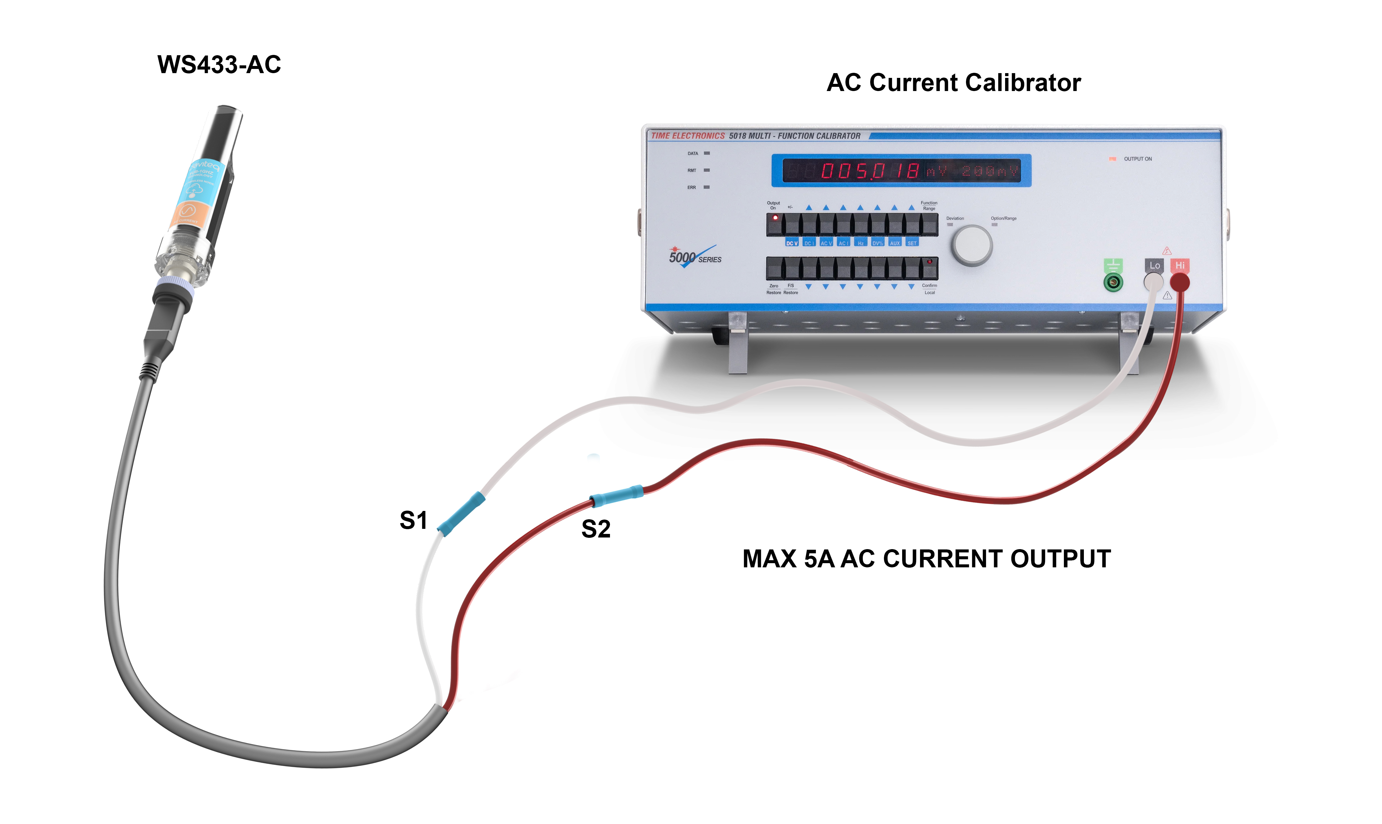
Diagram for re-calibrating the AC current transducer
4. Application notes for the Daviteq AC current transducer
The Daviteq AC current transducer together with a wireless transmitter to be used in the following cases:
- To measure the current load, power of the machine, equipment...to record the current load by time and detect when the load is over the threshold for protection, for safety.
- From the current load, the sensor can count the run time of the machine, equipment to deliver output how many hours of run, and how many hours of OFF, by setting the suitable threshold.
5. Installation Procedure
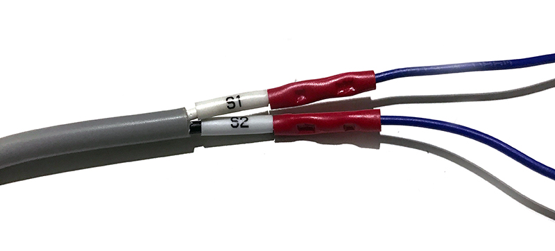
5.1 Connect the CT with the AC current transducer
Use the crimping tool to make the connection and protect the connection with a PVC heat shrink tube as below photos.

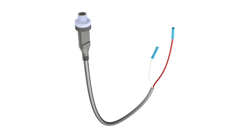
5.2 Connect the AC transducer to Wireless Transmitter
Connect the AC transducer to the wireless transmitter via the M12 connector.
Make sure the connection is firm and tight as in below photo.

6. Troubleshooting for the Daviteq AC current transducer
| No. | Phenomena | Reason | Solutions | |
| 1 | The measured value always shows Zero values. | 1.1 |
0.5A is the low cut value for this sensor. Therefore the actual load current (after multiplying the CT ratio) must be higher than 0.5A. |
Do nothing, it is the standard feature of the sensor. In case the measured load is too small, please make more loops on the CT, so that the measured current will be multiplied by the number of the loops. |
| 2 | The measured value is not as expected | 2.1 | The CT ratio is incorrect | Please check the actual ratio of CT and the configuration of CT in the wireless transmitter again. |
| 2.2 | Loosed connection of M12 connector of the transducer and wireless transmitter. | Check whether the M12 connector is firmly connected? | ||
| 2.3 | Wrong A and B values | Check the A & B in the configuration of the Wireless transmitter. Normally, A=1 and B=0. A & B can only be changed to other values when the transducer was re-calibrated by AC current calibrator. | ||
| 3 | HW_Error = 1 | 3.1 | Loosed connection of M12 connector of the transducer and wireless transmitter. | Check whether the M12 connector is firmly connected? |
| 3.2 | The transducer got a problem | Please consult the manufacturer for a warranty or replacement. |
7. Maintenance of the AC current transducer
There are no moving parts or consumed parts in the AC current transducer, therefore there is no need to do maintenance for the AC current transducer.
However, checking the grounding wire frequently is highly recommended.
8. Default configuration
This AC current transducer has the default configuration, however, those parameters cannot be changed. The user can change the configuration on the wireless transmitter so that the complete sensor (transducer + wireless) delivers the proper output value. Below are some configuration parameters that store in the flash memory of the wireless transmitter.
| Description | Unit | Default | Format | Property | Comment |
| CONSTANT_A | 1 | Float | R/W |
Constant a for scaling measured value |
|
| CONSTANT_B | 0 | Float | R/W |
Constant b for scaling measured value |
|
| HIGH_CUT | A | 1E+09 | Float | R/W |
High cut value for final value (after CT ratio) |
| LOW_CUT | A | 0.5 | Float | R/W |
Low cut value for final value (after CT ratio) |
| SENSOR_BOOT_TIME | mS | 1000 | Uint32 | R/W |
Boot time of sensor/input, in ms |
| CT | 40 | Float | R/W |
CT of current transformer |
END.
No Comments