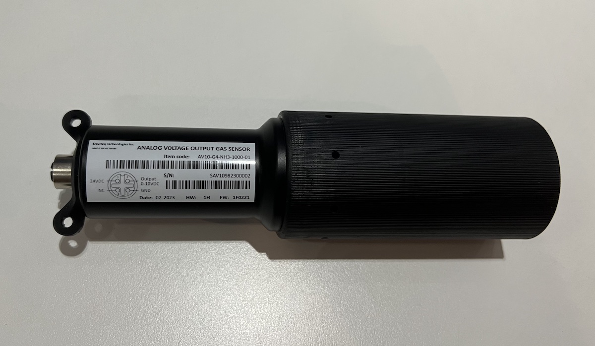
Manual for AV10-G4-NH3 sensor for Livestock
1. Introduction
Daviteq NH3 Gas sensor for Livestock is a NH3 gas measuring sensor that utilizes the Seri-4 electrochemical sensor with a high sensitivity to low concentrations of detected gas, high selectivity, and a stable baseline. It has an ultra-low noise amplifier to amplify the nano-ampere current signal from the sensor and delivers the stable and high-resolution output.
* For some applications with high humidity ambient all the time, the sensor can come with a heater to control the humidity within the working range of the sensor.
2. Calibration of the Daviteq NH3 Gas Sensor
2.1 Why do we need to calibrate the gas sensor? There are some reasons:
- The sensor current output of a sensor is different from the other sensor. It is not the same value for all sensors after manufacturing.
- The sensor current output of a sensor will be changed over time. For example, the NH3 sensor current output will be reduced by about 5% of the signal per six months in clean air at 25 oC temperature.
- The R_gain of the circuit also has a 0.1% or 0.05% tolerance;
Therefore, users need to calibrate the sensor before use or in a pre-defined interval time (6 or 12 months for example).
2.2 How to calibrate the NH3 Gas sensor?
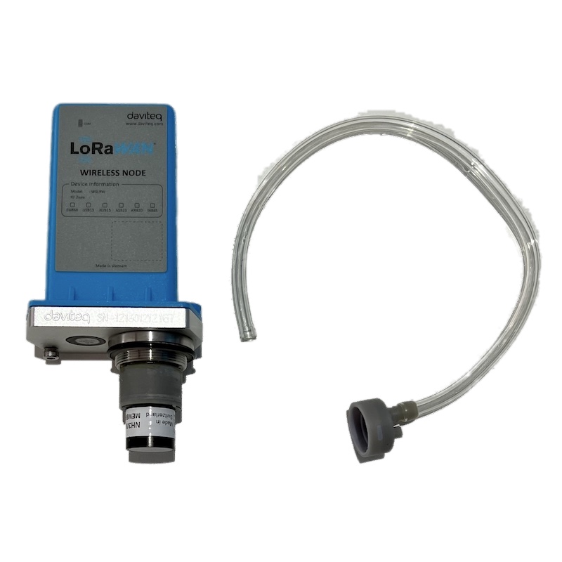
Instructions to attach the calibration cap onto the sensor module to get Zero or Span values.
|
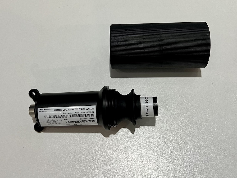
Step 1. Remove the Filter and prepare the calibration cap
|
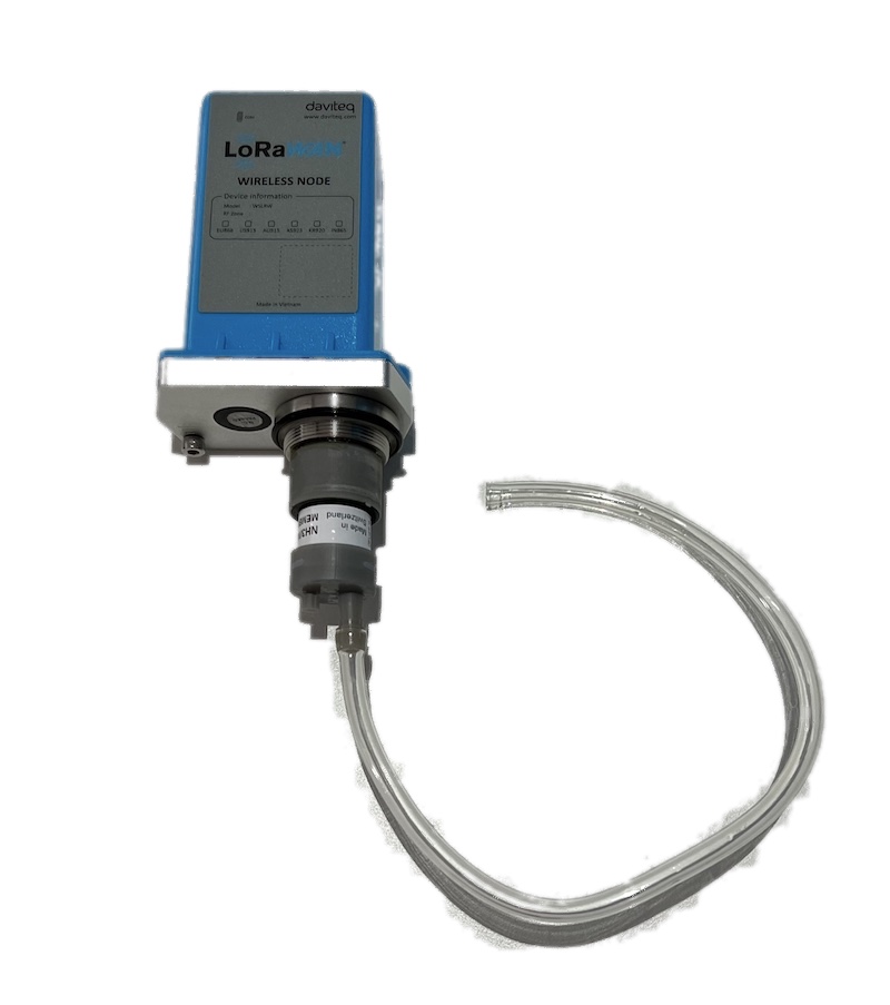
Step 2. Attach the calibration cap to the sensor head
|
|
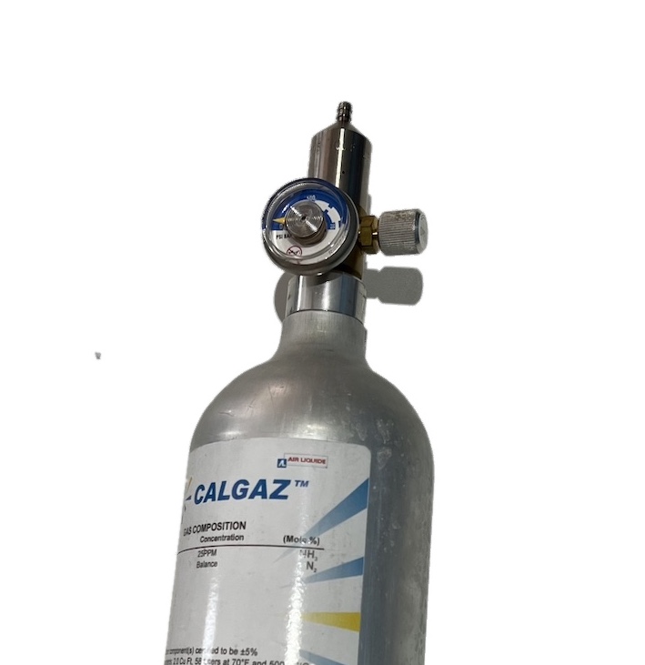
Step 3. Installed the Regulator to the Gas cylinder
|
Step 4. Attach the tube to the regulator
|
Please use the Flow Regulator with a flow rate of 2.5 LPM or 5.0 LPM.
Step 1: Get the Zero value.
- Power ON the device;
- Place the device in a clean-air environment (the target value is nearly zero) at a temperature from 20 - 30 oC, in at least 60 minutes. It is better to use the 99.99% Nitrogen gas as zero gas instead of clean air.
- After 60 minutes, record the Voltage output value. Recording multiple values in 5 minutes to calculate the average value.
Step 2: Get the Span value
Note: Keep the sensor Power ON all the time;
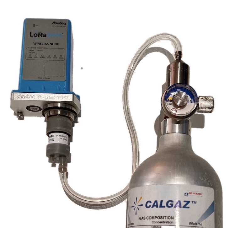
- Use the standard gas cylinder with a known concentration (for example NH3 in N2 with a concentration of 25ppm or 50ppm) to supply the gas to the sensor;
- Use the calibration cap as above pictures to attach to the sensor and connect the tubing to the gas cylinder;
- Open the valve on the Cylinder slowly and make sure the gas has reached the sensor. Please use the Flow regulator 2.5 LPM or 5.0 LPM.
Notes:
- The tube length is short as possible to reduce the gas loss.
- Press a timer to start counting the time;
- After 2 minutes, record the voltage output, then record voltage output value again at the minute of 3, 4, and 5. Calculate the average output value of the minutes of 3, 4, and 5.
- After that, immediately turn OFF the valve to save the gas;
- Remove the calibration cap from the sensor;
- Place the sensor in clean air again.
Note: Always keep the sensor Power ON all the time;
DO NOT PLACE THE SENSOR IN THE SPAN GAS FOR MORE THAN 5 MINUTES; IT WILL SATURATE THE SENSOR OUTPUT AND DEGRADE THE SENSOR LIFE QUICKLY.
Step 3: Entering values to reading device
- After Zero and Span, you will get the voltage output correspond to zero gas and span gas value;
- Enter these values into your reading device (PLC...) to get correct reading.
3. Installation
Notes:
* Avoid the place with humidity higher than 90% RH all the time (a short time in 2-3 days is acceptable)
* if the Sensor is intended to install outdoors, please use a rain guard to protect the sensor from rain and direct sunlight. Please contact us to buy this accessory.
3.1 Level of Installation
- Place the sensor in the area to monitor the target gas concentration. Please always check the gas molecular weight v.s the air.
- For example, NH3 gas has a lighter weight than air, so the sensor must be placed at a height higher than the source of NH3 leakage. Normally, the sensor will be mounted at a height of 1.6m from the ground.
3.2 Wiring
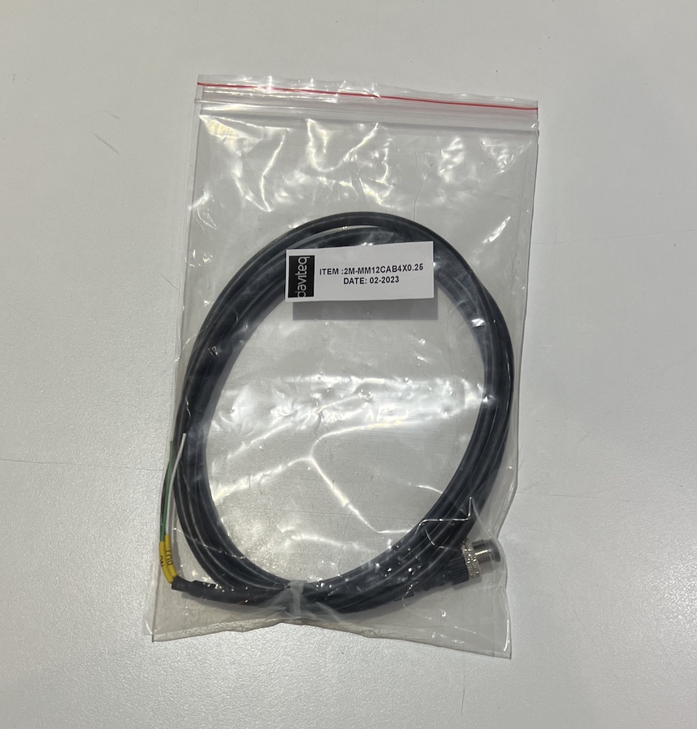
Use the M12-Male cable Coding A, 4 pin as below picture.
Because the Output is 0-10VDC, we do recommend to use the following cable for extention:
- Cable size: minimum 24AWG (or minimum 0.5 mm2 core)
- Cable type: Shielded
- Max recommended cable legnth: 20m
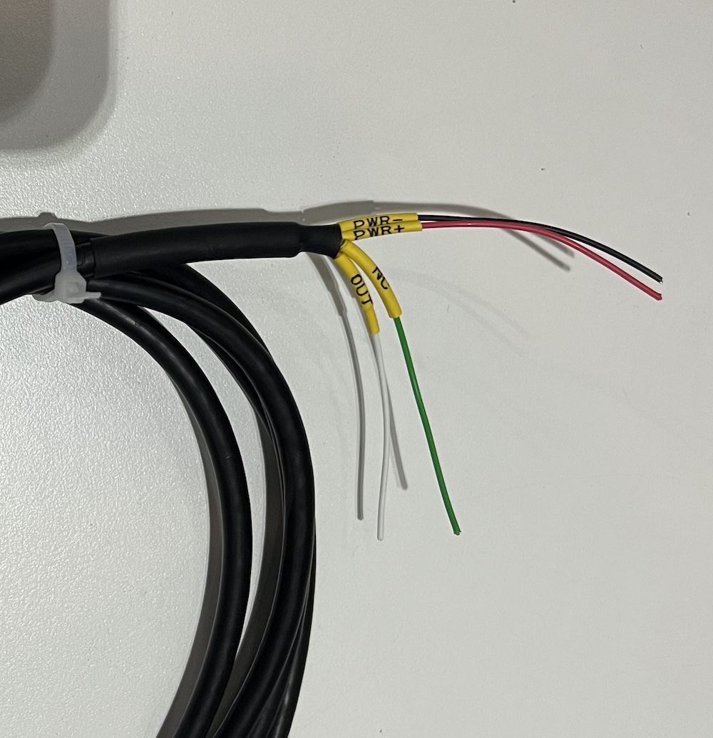
Connect the wires to Reading device as below:
- PWR+: 12-36VDC
- PWR-: GND
- OUT: 0-10VDC OUTPUT
- NC: Not used
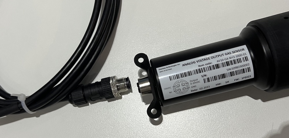
Plug the M12 connector to sensor
Firmly tighten the M12 connection:
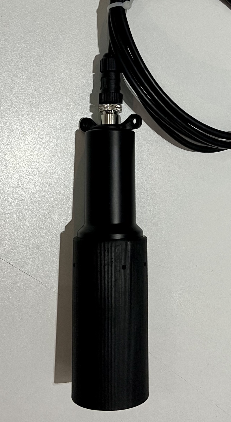
Recommend to use other rope (plastic rope or stainless steel rope) to hang the sensor, it will reduce the tension force of the signal cable.
4. Troubleshooting for the Daviteq NH3 Gas Sensor
| No. | Phenomena | Reason | Solutions | |
| 1 | The measured value is not within the expected value. | 1.1 | The sensor is drifted by time. | Re-calibrate the sensor |
| 1.2 | The sensor was in a high humidity environment (> 90% RH) for more than 03 days continuously. | Place the sensor in low humidity for its recovery. It may take up to 30 days to recover. If the sensor cannot recover after 30 days, please replace the new sensor module. | ||
| 2 | The measured value is always zero or near zero. | 2.1 | The sensor module was removed. | Please check the sensor. |
| 2.2 | The sensor is at the end of its life. | Replace the sensor module | ||
| 3 | The voltage output is 0V or random noise | 3.1 | The wiring problem | Check the wiring and connector M12. Check power supply. |
| 3.2 | The sensor is faulty | Contact manufacturer. |
5. Maintenance of the Daviteq NH3 Gas Sensor
| What? |
How? |
When? |
| Re-calibration |
The gas sensor may be drifting over time. Please check the sensor specification to identify the interval time for the re-calibration sensor. Please follow the calibration procedure as in above section. |
Approx. 6-12 months |
| Sensor replacement |
Replace the new sensor module after 1-2 years of operation (please check the sensor specification of each gas type). Please see below instructions. |
Approx. 1-2 years |
Sensor replacement instructions:
* Please disconnect the device before doing the following steps
|
Step 1. Remove the Protector by Rotate it anti-clockwise
|
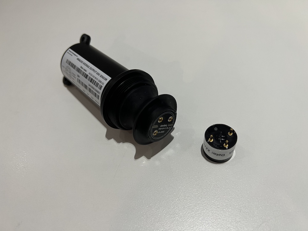
Step 2. Unplug the sensor module
|
|
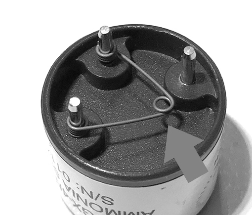
Step 3. Remove the spring clip on the new sensor module.
|
Step 4. Plug the new sensor module into the PCB
|
|
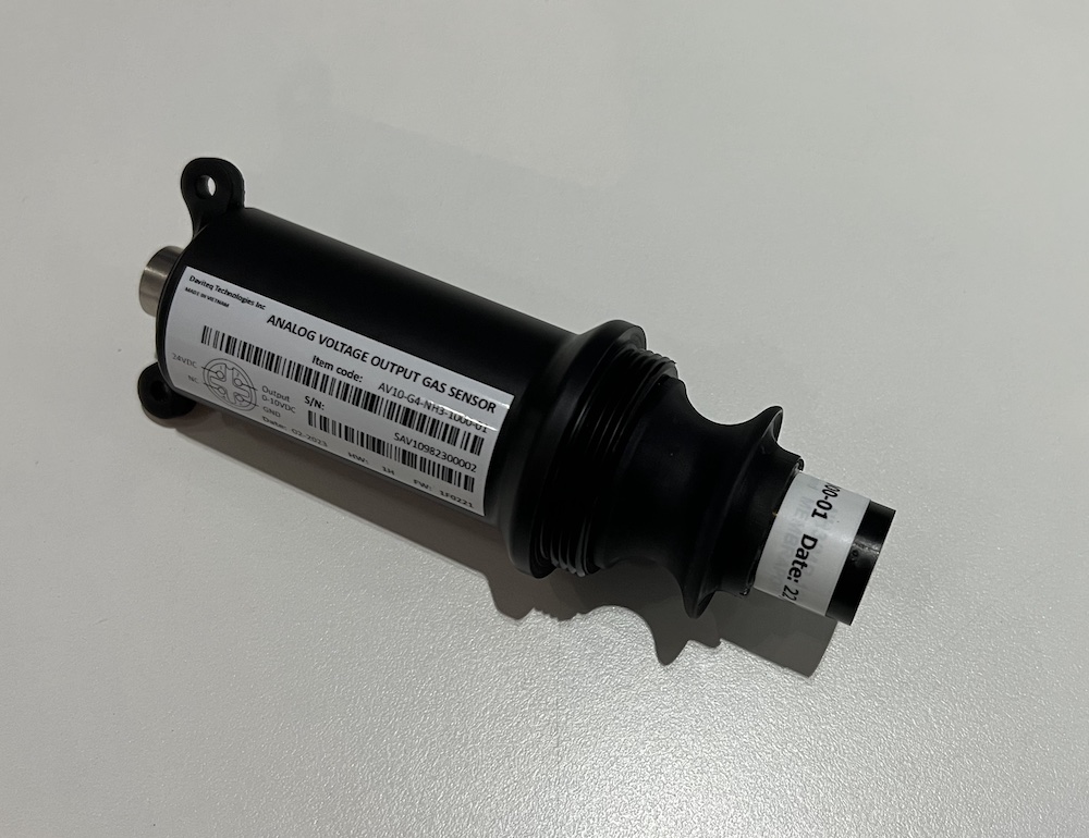
Step 5. Install the Protector back by Rotate it clock-wise
|
|
END.
No Comments