Daviteq AFD Air/Gas Flow Sensor
1. Overview
Daviteq AFD Air/Gas Flow Sensor is the flow probe that utilizes the Pitot tube measurement principle. This flow sensor is intended to use in the Duct Air of the HVAC system to measure the Air velocity and thus calculate the Air flow. The probe has various sizes to suit the pipe/duct size from 80mm to 2000mm in diameter.
2. Detail measurement principle and its specification
In the 18th century, French engineer Henri Pitot invented the Pitot tube, and in the mid-19th century, French scientist Henry Darcy modified it to its modern form. In the early 20th century, German aerodynamicist Ludwig Prandtl combined the static pressure measurement and Pitot tube into the Pitot-static tube, which is widely used today.
A schematic of a Pitot-static tube is shown in Figure 1. There are 2 openings in the tubes: one opening faces the flow directly to sense the stagnation pressure, and the other is perpendicular to the flow to measure the static pressure.
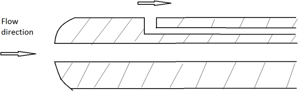
Figure 1. Schematic of a Pitot-static tube
The pressure differential is required to determine the flow speed, typically measured by pressure transducers. The below formula calculates the fluid velocity:
V = K x SQRT (DP)
Where:
- DP: Differential pressure measured by the sensor
- K: is the factor of the sensor design and the fluid type.
AFD flow sensor specification
| Sensor technology | Pitot tube flow sensor |
| Compatible gases | Air, Nitrogen, CO2, Oxygen. |
| Differential pressure range | +/- 2 in-H2O |
| Fluid velocity range | 0 - 28.5 m/s with Air at 25 oC |
| Max allowable static pressure | 270 in-H2O |
| Burst static pressure | 2800 in-H2O |
| Max allowable fluid velocity | 45 m/s (Air) at 25 oC |
| Drift | +/- 0.35m/s in 12 months (Air) |
| Accuracy | +/- 0.28 m/s in 0 .. + 50 oC (Air) |
| Output | DULP, via M12-M connector |
| Process connection | M34 x 1.5 male threads come with flange and gasket |
| Materials | Engineering plastic |
| Working Temperature | -20 .. + 85 oC |
| Working Humidity | 0 .. 95%RH |
| IP Rating | IP65 |
3. Calibration of the Daviteq AFD Air/Gas Flow Sensor
The Daviteq AFD Air/Gas Flow sensor is calibrated at the factory with Airflow. It is recommended the customer to re-calibrate the sensor every 12 months.
The local 3rd party can carry out the calibration, but the customer needs to order an accessory from the manufacturer for calibration.
In case of using the sensor with other gas (not with the Air), please configure the Density of Fluid (kg/m3) of the gas in the device. Please refer to the memory map in this link.
Notes:
* The calibration and configuration can only be done when the AFD probe is used with a Wireless transmitter like Sub-GHz (WS433-M12F-AFD) or LoRaWAN (WSLRW-M12F-AFD) or Sigfox (WSSFC-M12F-AFD
* After that, use the offline tool or downlink to configure A & B to the device.
4. Application notes for the Daviteq AFD Air/Gas Flow Sensor
The Daviteq AFD Air/Gas Flow Sensor together with a wireless transmitter to be used in the following cases:
- Air Duct of HVAC system;
- Hot air drying system;
- Cooling air system,...
It can be mounted on any shape of Duct or Pipe for sizes from 80mm to 2000mm.
5. Installation
.png)
Figure 2. Dimension drawing of AFD-0200
5.1 Mounting Direction
With Air/gas applications, the AFD flow sensor must be mounted as below figure. This ensures no fluid condensation inside the sensor for accurate and reliable measurement.
Notes:
* The Arrow on the probe must be in the same direction of fluid flow;
* Adjust the nozzle height so that the probe tip must be within the measurement zone (from 10% to 90% of the inner diameter of the pipe)
.jpeg)
Figure 3. Mounting direction of AFD flow sensor
D is the inner diameter of pipe
|
Figure 4. Wrong installation direction |
Figure 5. Not recommended installation direction |
.png)
.png)
5.2 Maximum misalignment
AFD flow sensor installation allows for a maximum misalignment of 3 degrees, as illustrated in the below figure. Misalignment beyond 3 degrees will cause errors in flow measurement.
.png)
Figure 6: Maximum misalignment
5.3 Up and Downstream Straight Pipe requirement
To ensure a homogeneous flow profile, it is necessary to mount the AFD flow sensor at a sufficient distance to narrow or bend of the pipe. The required upstream and downstream lengths for different types of obstacles are summarized in the following table:
|
Type of obstacle |
Min. upstream length |
Min. downstream length |
|
90° bend |
7 xD |
3x D |
|
2x90° bend in the same plane |
9xD |
3xD |
|
2x90° bend in perpendicular planes |
17 x D |
4xD |
|
concentric reducer |
7xD |
3xD |
|
concentric expander |
7xD |
3xD |
|
ball/gate valve, fully open |
24 x D |
4xD |
D: Inner pipe diameter
.png)
Figure 7. Maximum misalignment
1: upstream length; 2: downstream length; a: 90° bend; b: valve, open; c: 2x90° bend
5.4 Mounting Position
- The mounting position must be chosen such that access to the Device is always possible;
- Please take note of the specification of the flow sensor and wireless transmitter to ensure the complete set of devices is suitable for the process and environment of the installation.
5.5 Mounting the sensor AFD
5.5.1 Install the AFD sensor on the round pipe:
Follow these steps:
- Attach the nozzle with M34x1.5 female threads to the pipe. This work will be done by a professional mechanic;
- The Nozzle height is calculated so that the probe tip must be within the measurement zone;
- Cleaning the nozzle;
- Remove the neck out of the flange;
- Install the neck to the nozzle;
- Insert the probe into the flange neck and tighten the locking screw.
|
Figure 8. Install the probe into the Nozzle |
Figure 9. Fully installed probe on the round pipe |
.jpeg)
.jpeg)
5.5.2 Install the AFD sensor on the rectangular shape Duct:
Follow these steps:
- Drill a hole of 38mm diameter on the duct surface;
- Cleaning the hole;
- Place the gasket;
- Place the flange;
- Screwing the flange to the duct wall by using the self-tapping screws (supplied with the probe)
- Insert the probe into the flange neck and tighten the locking screw.
|
Figure 10. Install the probe into the rectangular duct |
Figure 11. The probe is completely installed on the rectangular duct |
.png)
.jpeg)
5.6 Adjust the orientation of the probe
- Unscrew the locking hex screw M4;
- Rotate the probe gently so that the arrow on the probe must be aligned with the pipe/duct direction. The misalignment must be not higher than 3 degrees;
- Tighten the locking screw again.
.png)
Figure 12. Adjust the orientation of the probe
5.7 Attach the Wireless Transmitter to the probe
.png)
Figure 13. Attach the wireless transmitter to the probe
6. Troubleshooting for the AFD Air/Gas Flow Sensor
| No. | Phenomena | Reason | Solutions | |
| 1 | The fluid velocity is very small or zero. | 1.1 | The probe orientation is wrong | Check and adjust the orientation again. |
| 1.2 | The connection between probe and wireless transmitter is not firm | Check the M12 connection again | ||
| 1.3 | Differential pressure sensor got a problem or Wireless transmitter got a problem. | Please consult the manufacturer for a warranty or replacement. | ||
| 2 | The probe or complete device vibrates during operation | 2.1 | Forget to tighten the screws during installation | Recheck the installation. |
| 3 | There is leakage of Air/Gas nearby the installation | 3.1 | The leakage could be from the O-ring, gasket, or sealing | Recheck the installation. |
| 4 | From system: HW_Error = 1 | 4.1 | The lost connection between the Probe and the wireless transmitter | Check the M12 connector and tighten it. |
| 4.2 | The Probe got a problem. | Please consult the manufacturer for a warranty or replacement. |
7. Maintenance of the AFD Air/Gas Flow Sensor
- There are no moving parts or consumed parts in the AFD Air/Gas Flow Sensor. Therefore there is no need to do maintenance.
- However, the pressure sensor in the probe will drift over time. We do recommend customer to re-calibrate it every 12 months. Please follow the calibration procedure in this link.
8. Default configuration
This AFD Air/Gas Flow Sensor has the default configuration. The user can change the configuration on the wireless transmitter so that the complete sensor (probe + wireless) delivers the proper output value. Below are some configuration parameters that store in the flash memory of the wireless transmitter.
| Description | Unit | Default | Format | Property | Comment |
| CONSTANT_A | 1 | Float | R/W |
Constant a for scaling pressure value (in Pa) |
|
| CONSTANT_B | 0 | Float | R/W |
Constant b for scaling pressure value (in Pa) |
|
| HIGH_CUT | 1E+09 | Float | R/W |
High cut value for scaled value |
|
| LOW_CUT | 0 | Float | R/W |
Low cut value for scaled value |
|
| SENSOR_BOOT_TIME | mS | 200 | Uint32 | R/W |
Boot time of sensor/input, in ms |
|
TEMPERATURE_OFFSET_X10 |
oC | 0 | int16 | R/W |
Offset adjustment for measured temperature value |
|
DENSITY_OF_FLUID |
kg/m3 | 1.225 | Float | R/W |
Fluid Density, default is Air |
END.
No Comments