Daviteq GHC Flammable Gas Sensor - Measurement Principle
1. Introduction
1.1 Overview
Daviteq GHC Gas sensor module is intended for the automatic continuous measurement of hydrocarbons or carbon dioxide concentration in the atmosphere. The sensor operating principle is based on NDIR technology, i.e. on selective absorption of LED-produced infrared radiation by gas molecules. The differential dual wavelength method allows the elimination of water vapor, optical elements contamination, and other non-selective hindrances influence.
It has ultra-low power consumption to allow it to be integrated with Wireless Devices such as Sub-GHz transmitter, Sigfox transmitter, LoRaWAN transmitter, RS485 output transmitters, etc.
It can be calibrated with target gas like CH4, C3H8, C2H4, and C2H6...
Typical Applications: Flammable gas detection.
1.2 Specification
| Sensor technology | LED-based NDIR |
| Gas sampling method | Diffusion |
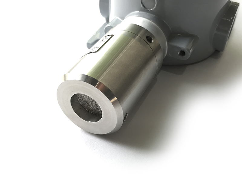
| Sensor housing / Rating | SS316/SS304 housing with 316SS sintered filter / for Indoor use (buy the optional accessory rain-guard for outdoor installation), Exd approval for Zone 1 or Zone installation. |
| Target gas | CH4, CH4/CH4+C2H6, C3H8, C2H4,... please consult us for other HC gases |
| Ambient Humidity | 0 - 98% |
| Temperature | -40 .. + 60 oC |
| Atmospheric pressure | 80 .. 120 kPa |
| Warm-up time | 120 sec |
| Measurement range, % vol. | 0 .. 5% vol. CH4, 0 .. 100% vol. CH4, for other ranges please consult us |
| Reading Stability in +20 .. + 25 oC |
± 0.1% vol. or ± 5% of readings (whichever is greater) for CH4 ± 0.05% vol. or ± 5% of readings (whichever is greater) for C3H8 |
| Zero Stability in +20 .. + 25 oC |
for CH4: ± 0.1% vol. or ± 2% LEL |
| Response time T90 | <= 30 sec (with sintered metal filter) |
| Sensor lifetime | >= 10 years |
| Calibration interval | Recommend recalibrating zero and span at least every 30 months |
Detailed reading stability
| Calibration Gas |
Readings stability within a temperature range |
Additional variability due to pressure |
Additional variability due to humidity |
| CH4 |
± 0.1% vol. or ± 5% of readings (whichever is greater) within the range of +20...+25 °C; |
± 0.2% vol. or ± 30% of readings (whichever is greater) at 100 kPa (test: 80 kPa, 100 kPa, 120 kPa) |
± 0.2% vol. or ± 15% of readings (whichever is greater) at 40 °C (test: 20% RH, 50% RH, 90% RH) |
|
± 0.2% vol. or ± 10% of readings (whichever is greater) within the range of |
|||
|
± 0.4% vol. or ± 20% of readings (whichever is greater) within the range of |
|||
| C3H8 |
± 0.05% vol. or ± 5% of readings (whichever is greater) within the range of +20...+25 °C; |
± 0.1% vol. or ± 30% of readings (whichever is greater) at 100 kPa (test: 80 kPa, 100 kPa, 120 kPa) |
± 0.1% vol. or ± 15% of readings (whichever is greater) at 40 °C (test: 20% RH, 50% RH, 90% RH) |
|
± 0.1% vol. or ± 10% of readings (whichever is greater) within the range of |
|||
|
± 0.2% vol. or ± 20% of readings (whichever is greater) within the range of |
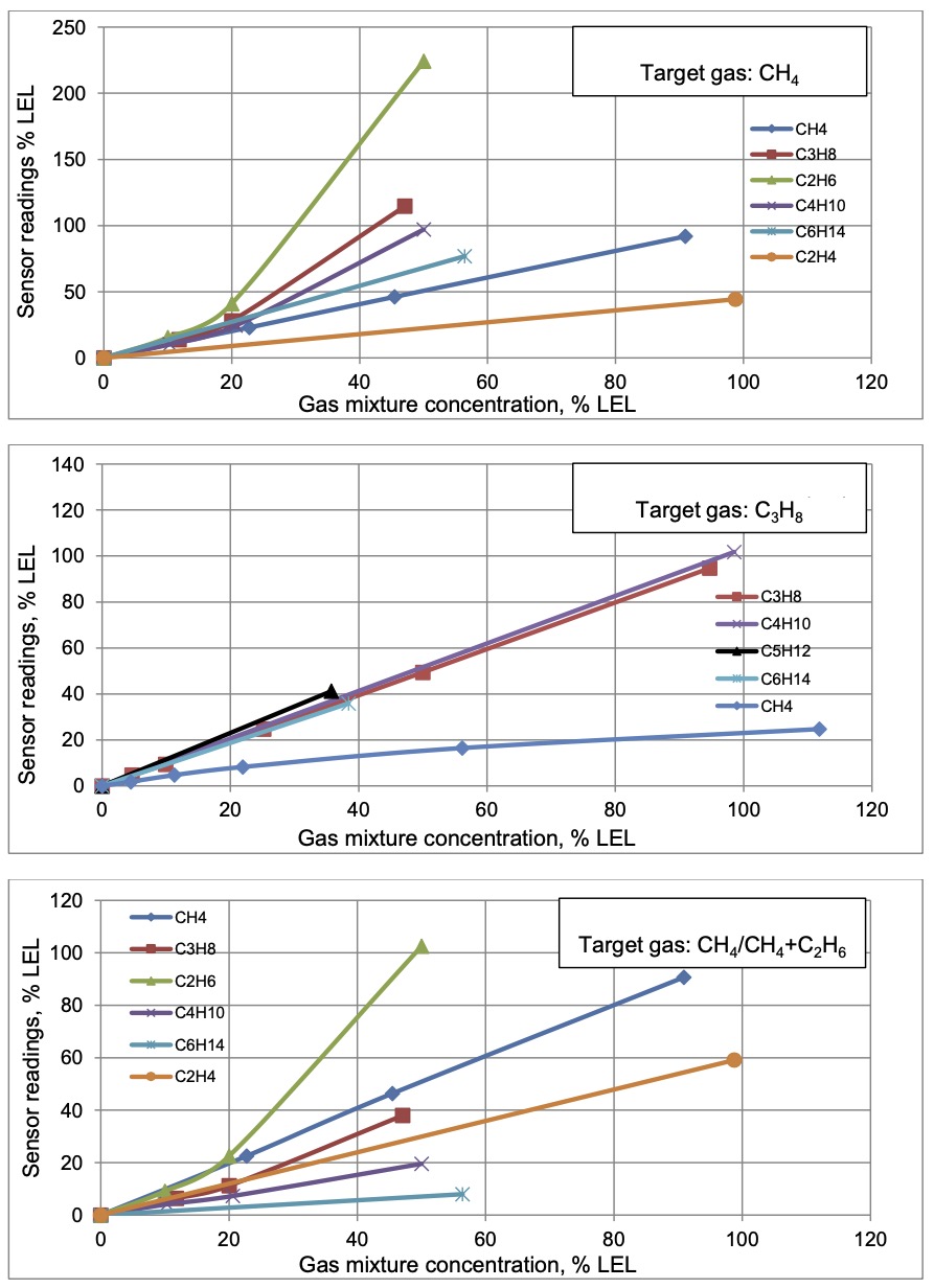
1.3 Cross-Sensitivity Data
What is cross-sensitivity?
The gas detection sensor is usually affected by other gas. It meant the sensor not only measure the target gas but also the other gases. If there is a concentration of additional gas, it would also cause a change in sensor output with a factor listed in the below table.
2. Principle of operation
When infrared radiation interacts with gas molecules, infrared light is absorbed by the gas molecules at a particular wavelength, causing vibration of the gas molecules. NDIR (Non-Dispersive Infrared) gas sensors detect a decrease in transmitted infrared light which is in proportion to the gas concentration. This transmittance, the ratio of transmitted radiation energy to incident energy, is dependent on the target gas concentration.
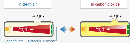
NDIR gas sensor consist of an infrared source, detector, optical filter, gas cell, and electronics for signal processing. A single light source, dual wavelength type gas sensor has two detectors and two optical filters of different wavelengths which are placed in front of each detector. The infrared light that is absorbed by a target gas passes through the active filter with a particular bandwidth for the detection of the target gas. The infrared light that does not interact with the target gas passes through the reference filter. The difference between transmitted light intensities in these two bandwidths is converted into gas concentration. The dual wavelength sensor ensures stable measurements for a long period of operation as the aging effects of the light source or the gas cell are automatically compensated by output signals at the reference wavelength.
Mid-infrared radiation through sample gas causes a resonance of gas molecules at their natural frequency with the infrared light in the spectrum region where the energy level of infrared is equivalent to the natural frequency of gas molecules, resulting in the absorption of infrared by gas molecules in the form of molecular vibration.
The relationship between infrared transmittance and gas concentration is expressed by the Lambert-Beer law:

Where T is transmittance, I is the intensity of light passed through sample gas and an optical filter, Io is the initial light intensity emitted from the source, ε is the molar attenuation coefficient, c is gas concentration, and d is the light path length.
Because ε of the target gas and the light pass length d are fixed with an NDIR sensor, gas concentration can be measured by measuring the transmittance within the spectrum region of the absorbed energy (wavelength) by the target gas.
The initial light intensity emitted from the light source Io is preset by calibration using zero gas which does not absorb infrared light. The initial value of the molar extinction coefficient ε is set by calibration using calibration gas of known concentration.
3. Calibration of the Daviteq GHC Gas Sensor
The Daviteq GHC Gas Sensor must be connected to a reading device, it usually is a wireless transmitter like Sub-GHz, Sigfox, or LoRaWAN.
3.1 Why do we need to calibrate the gas sensor? There are some reasons:
- The output value of a sensor is different from the other sensor. It is not the same value for all sensors after manufacturing.
- The output value of a sensor will be changed over time.
Therefore, users need to calibrate the sensor before use or in a pre-defined interval time (30 months for example).
3.2 How to calibrate the GHC Flammable Gas sensor?
NOTE: THE CALIBRATION CAN ONLY BE DONE IN THE SAFE ZONE!!!
Instructions to attach the calibration cap onto the sensor module to get Zero or Span values.
|
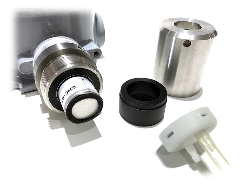
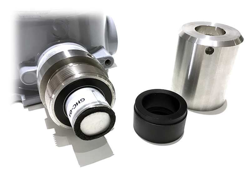
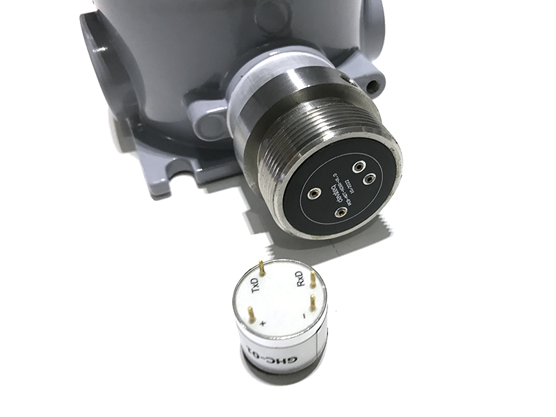
Step 1. Remove the Filter and prepare the calibration cap
|
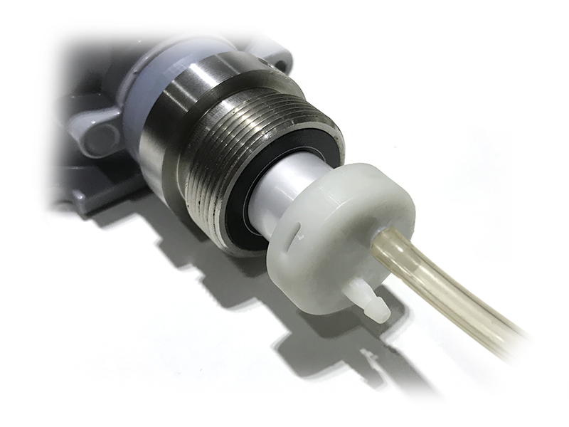
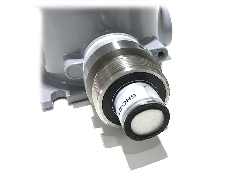
Step 2. Attach the calibration cap to the sensor head
|
|
Step 3. Installed the Regulator to the Gas cylinder
|
Step 4. Attach the tube to the regulator
|
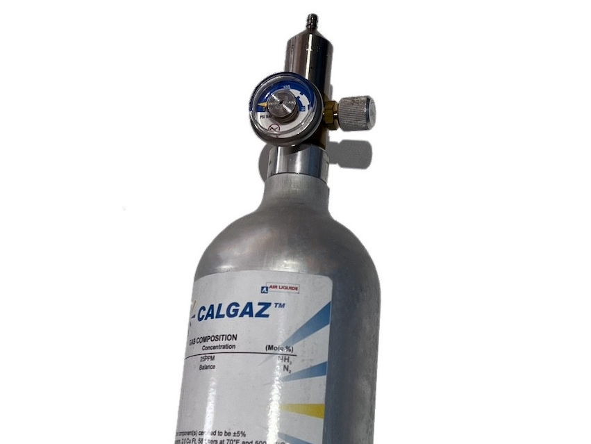
Please select the flow regulator with a flow rate of 2.5 LPM or 5.0 LPM.
With the 2-point calibration method, the user can define the A and B factors. Please find below the steps of calibration.
Step 1: Get the Zero value.
- Power ON the device;
- Place the device in a clean-air environment (the target value is nearly zero) at a temperature from 20 - 30 oC, in at least 60 minutes.
- After 60 minutes, force the device to send data, read and record the Raw_value, so now you got the Zero_value = Raw_GHC value.
Recommendation: Record many Raw_GHC values at least 10 minutes apart (10 values).
Zero value is the average of the recorded Raw values.
Note: the Raw_GHC values can be positive or negative; Its value is usually 7 (%LEL)
Step 2: Get the Span value
Note: Keep the sensor Power ON all the time;
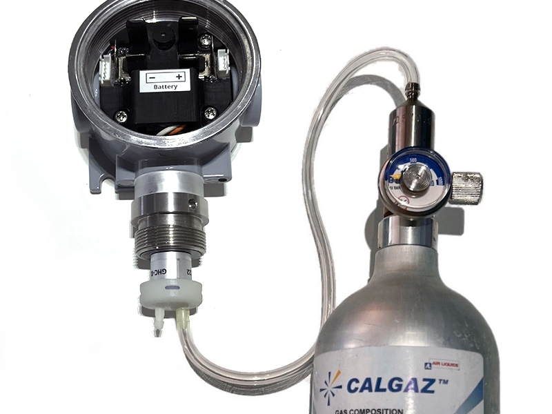
- Use the standard gas cylinder with a known concentration (for example Eythylene Air 1.35% is equivalent to 50 %LEL ) to supply the gas to the sensor;
- Use the calibration cap as above pictures to attach to the sensor and connect the tubing to the gas cylinder;
- Open the valve on the Cylinder slowly and make sure the gas has reached the sensor. The flow regulator should be 2.5LPM or 5.0LPM.
Notes:
- The tube length is short as possible to reduce the gas loss;
- Press a timer to start counting the time;
- After 2 minutes, force the device to send data once every minute, and stop forcing at 5 minutes;
- The highest Raw_value is the Span value.
Note: just get one value for Span
- After that, immediately turn OFF the valve to save the gas;
- Remove the calibration cap from the sensor;
- Place the sensor in clean air again.
Note: Always keep the sensor Power ON all the time;
Step 3: Calculate the new A and B
-The calculation of new A, B value based on basic linear formula: y = A * x + B
Where:
A, B is calibration coefficients
x is the sensor process value (example gas level in ppm) read on reading device such as on application server/network server, on offline tool. The process value is the RAW_VALUE in the payload
y is the correct value. y is the value of standard gas/standard condition
Which condition of Zero value: y0=A * x0 + B
Which condition of Span value: ys=A * xs+ B
From the two formulas, the calculation of A, B as below
A = (y0 - ys) / (x0 - xs)
B = (ys * x0 - y0 * xs)/ (x0 - xs)
-Example of A, B calculation for LoraWAN Ammonia Gas sensor (item code WSLRW-G4-NH3-100-01):
* With condition of clean-air environment at a temperature from 20 - 30 oC, there is no ammonia gas (y0 = 0); while the NH3 level on reading device (RAW_VALUE in the payload) is -0.25 (x0 = -0.25)
* When the sensor is connected to standard gas cylinder having ammonia level of 25 ppm (ys = 25); while the NH3 level on reading device (RAW_VALUE in the payload) is 18.66 (xs = 18.66)
*The calculation of A, B for the Ammonia gas sensor:
A = (0 - 25) / (-0.25 - 18.66) =1.32205
B = (ys * x0 - y0 * xs)/ (x0 - xs) = (25 * (-0.25) - 0 * 18.66)/ (-0.25 - 18.66) = 0.33051
The factory default A = 1 and default B = 0
The RAW_VALUE in the payload is used for calibration
Step 4: Configure the new A and B into the device
- User can use the off-line tool or downlink to write the values of A and B;
- Writing the new A and B successfully meant you had done the calibration process. Congratulation!
4. Application notes for the Daviteq GHC flammable Gas Sensor
-
Do not use a damaged sensor. It must be repaired only by personnel authorized by the manufacturer.
-
Keep the sensor out of contact with aggressive substances e.g. acidic environments, which can react with metals, as well as solvents, which may affect polymeric materials.
-
Diffusion holes of the sensor should be protected against the ingress of sprayed liquid or waterdrops.
-
The sensor is not intended to measure the target gas concentration contained in fluids.
-
Correct measurement is provided when the ambient temperature changes not faster than 0.6 °C/min.
- Inspection and maintenance should be carried out by suitably trained personnel.
-
Persons, who have studied this UM, must be briefed on safety precautions when operating electrical equipment intended for use in explosive areas in due course.
-
When dealing with a cylinder containing a gas mixture under pressure, it is necessary to follow safety regulations.
-
There is no risk of pollution or negative impact on human health. The sensor does not contain any harmful substances that may be released during its normal operation.
5. Installation notes
Notes:
* If a sensor has been kept in transport containers at temperatures below zero centigrade, leave it at +10...+35 °C for not less than one hour.
* if the Sensor is intended to install outdoors, please use a rain guard to protect the sensor from rain and direct sunlight. Please contact us to buy this accessory.
- Place the sensor in the area to monitor the target gas concentration. Please always check the gas molecular weight v.s the air.
Note for Outdoor installation: For outdoor installation, please use the Rain guard to protect the sensor from raindrops or snowflakes. Please contact us to buy the Rainguard.
6. Troubleshooting for the Daviteq GHC Flammable Gas Sensor
| No. | Phenomena | Reason | Solutions | |
| 1 | The measured value is not within the expected value. | 1.1 | The sensor is drifted by time. | Re-calibrate the sensor |
| 1.2 | The sensor was spoiled. | Please consult the manufacturer for a warranty or replacement. | ||
| 2 | The measured value is always zero or near zero. | 2.1 | The sensor module was removed. | Please check the sensor. |
| 2.2 | The sensor is at the end of its life. | Replace the sensor module | ||
| 3 | HW_Error = 1 | 3.1 | Loosed connection of sensor module and wireless transmitter. | Check the internal wiring. |
| 3.2 | The measuring module got a problem. | Please consult the manufacturer for a warranty or replacement. |
7. Maintenance of the Daviteq GHC Flammable Gas Sensor
| What? |
How? |
When? |
| Cleaning the Filter |
Check and clean the filter every few months, depending on the environment. Clean the filter with warm water and soap, then use compressed air to purge it from the inside out. |
Approx. 6-12 months |
| Re-calibration |
The gas sensor may be drifting over time. Please check the sensor specification to identify the interval time for the re-calibration sensor. Please follow the calibration procedure in section 3 above. |
Approx. 30 months |
| Sensor replacement |
Replace the new sensor module only when the sensor cannot respond with standard calibration gas. |
> 10 years or when problem occurs. |
Sensor replacement instructions:
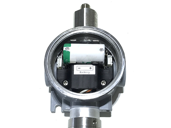
* Please remove the batteries before doing the following steps
|
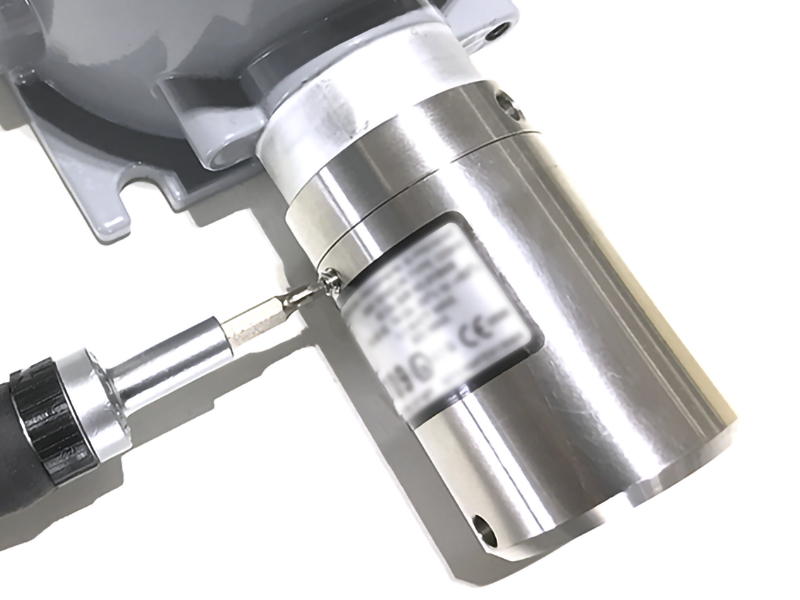
Step 1. Unscrew the housing
|
Step 2. Remove the filter
|
|
Step 3. Unplug the sensor module
|
Step 4. Plug the new sensor module into the PCB
|
|
Step 5. Insert the batteries and start calibration of the new sensor as per section 3.
|
Step 6. Place the filter back.
|
8. Default configuration
This GHC gas sensor module has the default configuration, however, those parameters can be changed. The user can change the configuration on the wireless transmitter so that the complete sensor (transducer + wireless) delivers the proper output value. Below are some configuration parameters that store in the flash memory of the wireless transmitter.
| Description | Unit | Default | Format | Property | Comment |
| CONSTANT_A | 1 | Float | R/W |
Constant a for scaling measured value. This value would be changed after calibration. |
|
| CONSTANT_B | 0 | Float | R/W |
Constant b for scaling measured value. This value would be changed after calibration. |
|
| HIGH_CUT | 1E+09 | Float | R/W |
High cut value for scaled_value |
|
| LOW_CUT | 0 | Float | R/W |
Low cut value for scaled_value |
|
| SENSOR RESPONSE TIME | S | 100 | uint16 | R/W |
* Do not change this value |
| C_H_FACTOR | 4.4 | Float | R/W |
4.4 for CH4, 1.7 for C3H8 |
END.
No Comments