Daviteq G4 Gas Sensor - Measurement Principle
1. Introduction
1.1 Overview
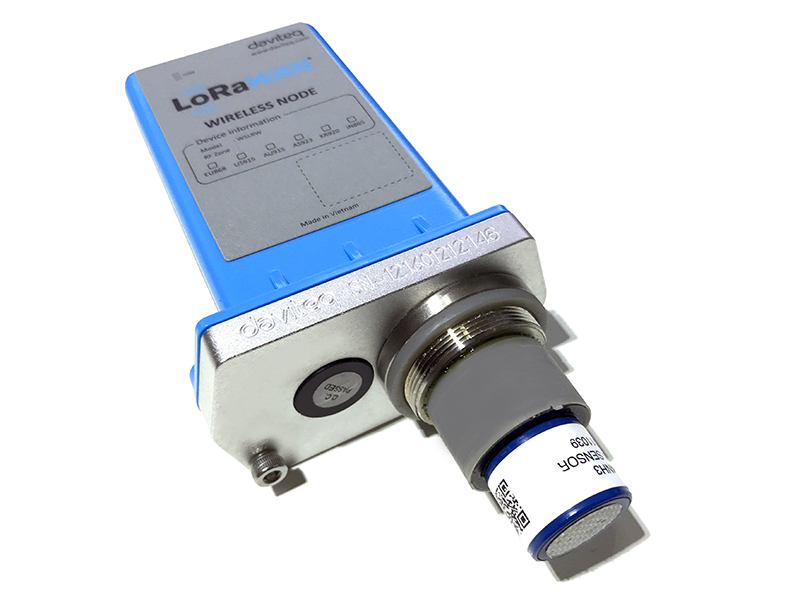
Daviteq G4 Gas sensor module is a gas measuring module that utilizes the Seri-4 electrochemical sensor with a high sensitivity to low concentrations of detected gas, high selectivity, and a stable baseline. It has an ultra-low noise amplifier to amplify the nano-ampere current signal from the sensor and delivers the stable and high-resolution output to the reading devices such as Sub-GHz transmitter, Sigfox transmitter, LoRaWAN transmitter, RS485 output transmitter, etc.
The module can support various types of gas sensors such as CO, NO, NO2, H2S, NH3, O2, O3, SO2, Cl2, HCHO...
Typical Applications: Gas, toxic gas detecting, air quality monitoring for facility, building, pump station, HVAC...
* For some applications with high humidity ambient all the time, the sensor can come with a heater to control the humidity within the working range of the sensor.
1.2 Specification
| Sensor technology | Seri-4 electrochemical gas sensor. Please check this link for the specifications of each gas type. |
| Sensor housing / Rating | SS316/SS304 housing with 316SS sintered filter / for Indoor use (buy the optional accessory rain-guard for outdoor installation) |
Note: Do not install the sensor where the ambient humidity is higher than 90% RH most of the time! It will cause the sensor to malfunction.
1.3 Cross Sensitivity Data
What is cross-sensitivity?
The electrochemical sensor is normally affected by other gas. It meant the sensor not only measure the target gas but also the other gases. If there is a concentration of other gas, it would also cause the change in sensor output with a factor listed in the below table.
Please check the cross-sensitivity data of each gas type in this link.
2. Detail measurement principle
The very low current from the gas sensor is amplified by a special amplifier circuit to deliver stable and high resolution.
The special mechanism provides noise filtering so that it can deliver a very stable output. The ADC chip can provide a resolution from 16-bit to 24-bit.
The circuit will deliver the digital output to the reading device.
With an ultra-low-power design, it can run by battery for 10-20 years!
The G4 sensor module will deliver 02 values:
- Gas concentration, in ppm or ppb.
- The temperature of the circuit board, in oC.
3. Calibration of the Daviteq G4 Gas Sensor
The Daviteq G4 Gas Sensor must be connected to a reading device, normally it is a wireless transmitter like Sub-GHz, Sigfox, or LoRaWAN.
In the reading device, the following parameter is configured in advanced:
Sensor+amplifier sensitivity (mV/ppm): it is the voltage output of the amplifier circuit = Sensor current output (nA/ppm) x R_gain
For example, with an NH3 gas sensor, the default value of the Sensor current output is 110nA/ppm and R_gain = 100 Kohms.
Therefore, the default NH3 Sensor+amplifier sensitivity = 11 mV/ppm
Depending on the sensor type and R_gain value, the sensor sensitivity must be calculated and pre-configured into the reading device.
3.1 Why do we need to calibrate the gas sensor? There are some reasons:
- The sensor current output of a sensor is different from the other sensor. It is not the same value for all sensors after manufacturing.
- The sensor current output of a sensor will be changed over time. For example, the NH3 sensor current output will be reduced by about 5% of the signal per six months in clean air at 25 oC temperature.
- The R_gain of the circuit also has a 0.1% or 0.05% tolerance;
Therefore, users need to calibrate the sensor before use or in a pre-defined interval time (6 or 12 months for example).
3.2 How to calibrate the G4 Gas sensor?
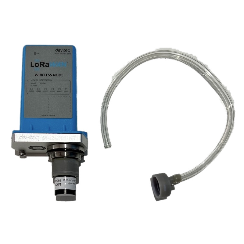
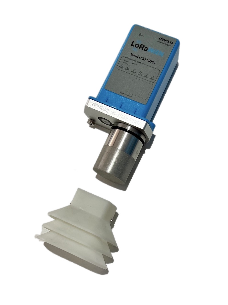
Instructions to attach the calibration cap onto the sensor module to get Zero or Span values.
|
Step 1. Remove the Filter and prepare the calibration cap
|
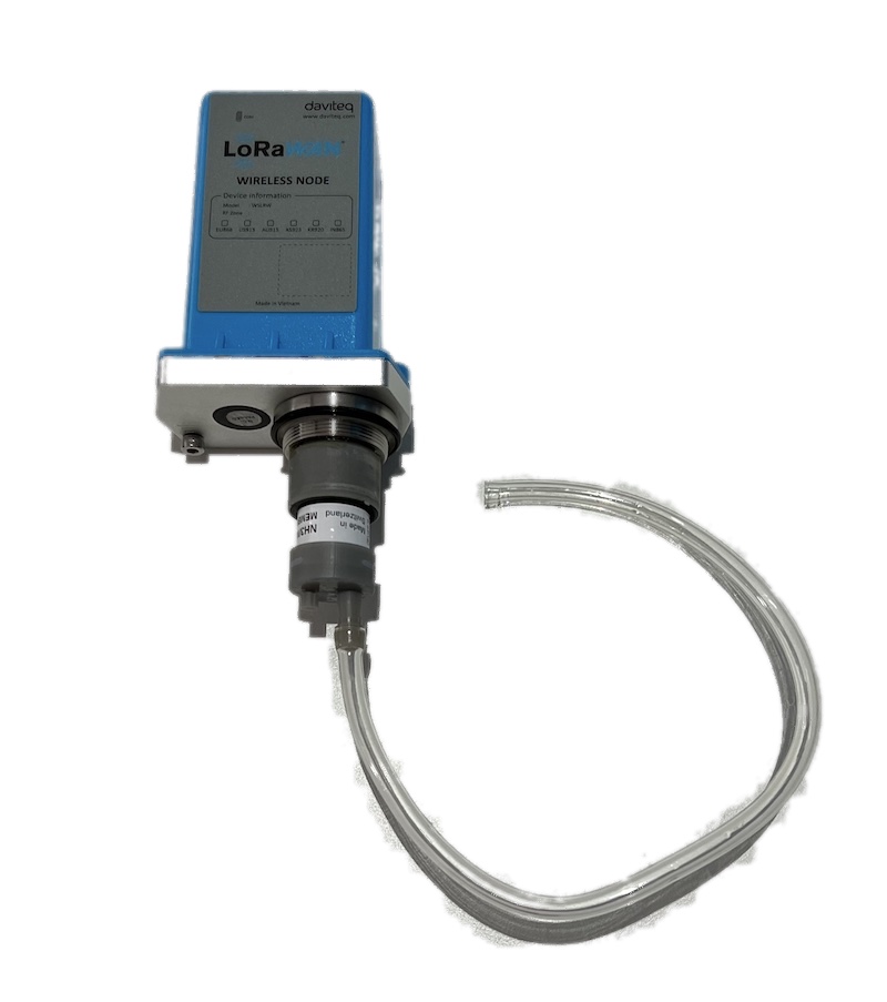
Step 2. Attach the calibration cap to the sensor head
|
|
Step 3. Installed the Regulator to the Gas cylinder
|
Step 4. Attach the tube to the regulator
|
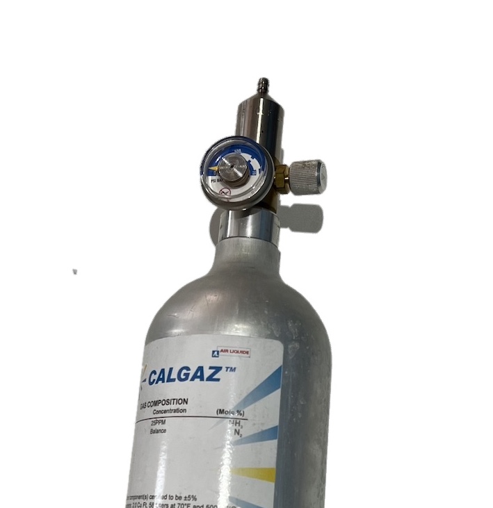
Please use the Flow Regulator with a flow rate of 2.5 LPM or 5.0 LPM.
With the 2-point calibration method, the user can define the A and B factors. Please find below the steps of calibration.
Step 1: Get the Zero value.
- Power ON the device;
- Place the device in a clean-air environment (the target value is nearly zero) at a temperature from 20 - 30 oC, in at least 60 minutes. It is better to use the 99.99% Nitrogen gas as zero gas instead of clean air.
- After 60 minutes, force the device to send data, read and record the Raw_value.
- Recommendation: Record many Raw values at least 10 minutes apart (10 values).
Zero value is the average of the recorded Raw values
Note: the Raw_value can be positive or negative; it will be in the range of -3.00 to +3.00 ppm
Step 2: Get the Span value
Note: Keep the sensor Power ON all the time;
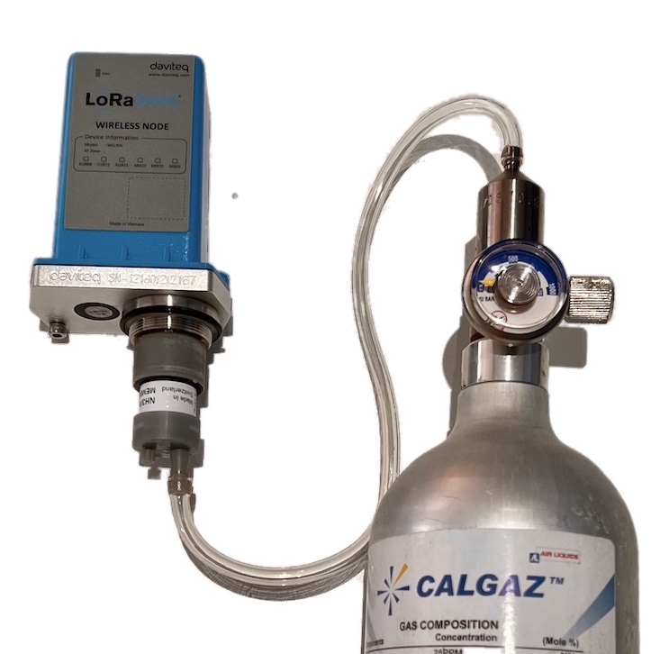
- Use the standard gas cylinder with a known concentration (for example NH3 in N2 with a concentration of 25ppm or 50ppm) to supply the gas to the sensor;
- Use the calibration cap as above pictures to attach to the sensor and connect the tubing to the gas cylinder;
- Open the valve on the Cylinder slowly and make sure the gas has reached the sensor. Please use the Flow regulator 2.5 LPM or 5.0 LPM.
Notes:
- The tube length is short as possible to reduce the gas loss.
- Press a timer to start counting the time;
- After 2 minutes, force the device to send data once every minute, and stop forcing at 5 minutes. The highest Raw_value is the Span value.
Note: Just get one value for Span
- After that, immediately turn OFF the valve to save the gas;
- Remove the calibration cap from the sensor;
- Place the sensor in clean air again.
Note: Always keep the sensor Power ON all the time;
DO NOT PLACE THE SENSOR IN THE SPAN GAS FOR MORE THAN 5 MINUTES; IT WILL SATURATE THE SENSOR OUTPUT AND DEGRADE THE SENSOR LIFE QUICKLY.
Step 3: Calculate the new A and B
-The calculation of new A, B value based on basic linear formula: y = A * x + B
Where:
A, B is calibration coefficients
x is the sensor process value (example gas level in ppm) read on reading device (RAW_VALUE in the payload) such as on application server/network server, on offline tool
y is the correct value. y is the value of standard gas/standard condition
Which condition of Zero value: y0=A * x0 + B
Which condition of Span value: ys=A * xs+ B
From the two formulas, the calculation of A, B as below
A = (y0 - ys) / (x0 - xs)
B = (ys * x0 - y0 * xs)/ (x0 - xs)
-Example of A, B calculation for LoraWAN Ammonia Gas sensor (item code WSLRW-G4-NH3-100-01):
* With condition of clean-air environment at a temperature from 20 - 30 oC, there is no ammonia gas (y0 = 0); while the NH3 level on reading device (RAW_VALUE in the payload) is -0.25 (x0 = -0.25)
* When the sensor is connected to standard gas cylinder having ammonia level of 25 ppm (ys = 25); while the NH3 level on reading device (RAW_VALUE in the payload) is 18.66 (xs = 18.66)
*The calculation of A, B for the Ammonia gas sensor:
A = (0 - 25) / (-0.25 - 18.66) =1.32205
B = (ys * x0 - y0 * xs)/ (x0 - xs) = (25 * (-0.25) - 0 * 18.66)/ (-0.25 - 18.66) = 0.33051
The factory default A = 1 and default B = 0
Use RAW_VALUE in the payload on the reading device for calibration
Step 4: Configure the new A and B into the device
- User can use the off-line tool or downlink to write the values of A and B;
- Writing the new A and B successfully meant you had done the calibration process. Congratulation!
4. Application notes for the Daviteq G4 Gas Sensor
Depending on what type of gas sensor is used in the G4 gas module, the applications will be different. Please refer for some applications:
| Gas type | Typical applications |
| NH3 Ammonia Gas | NH3 leakage detection for HVAC, Chiller... NH3 concentration in the toilet NH3 concentration in the animal farms; chicken, pig, cow... NH3 concentration in the ambient air (Air quality monitor) |
| H2S |
H2S gas monitor for the sewage treatment system H2S gas monitor for basement floor H2S gas monitor for solid waste treatment plant... |
| Cl2 Chlorine gas |
Chlorine gas leakage detection in the chemical process plant Chlorine gas monitoring in ambient air in the water treatment plant Chlorine toxic gas monitoring in the City ... |
5. Installation notes
Notes:
* Avoid the place with humidity higher than 90% RH all the time (a short time in 2-3 days is acceptable)
* if the Sensor is intended to install outdoors, please use a rain guard to protect the sensor from rain and direct sunlight. Please contact us to buy this accessory.
- Place the sensor in the area to monitor the target gas concentration. Please always check the gas molecular weight v.s the air.
- For example, NH3 gas has a lighter weight than air, so the sensor must be placed at a height higher than the source of NH3 leakage. Normally, the sensor will be mounted at a height of 1.6m from the ground.
- For NH3 Odor detection in the toilet, users can place the sensor from 1.6m on the wall or on the ceiling which a height <= 2.6m
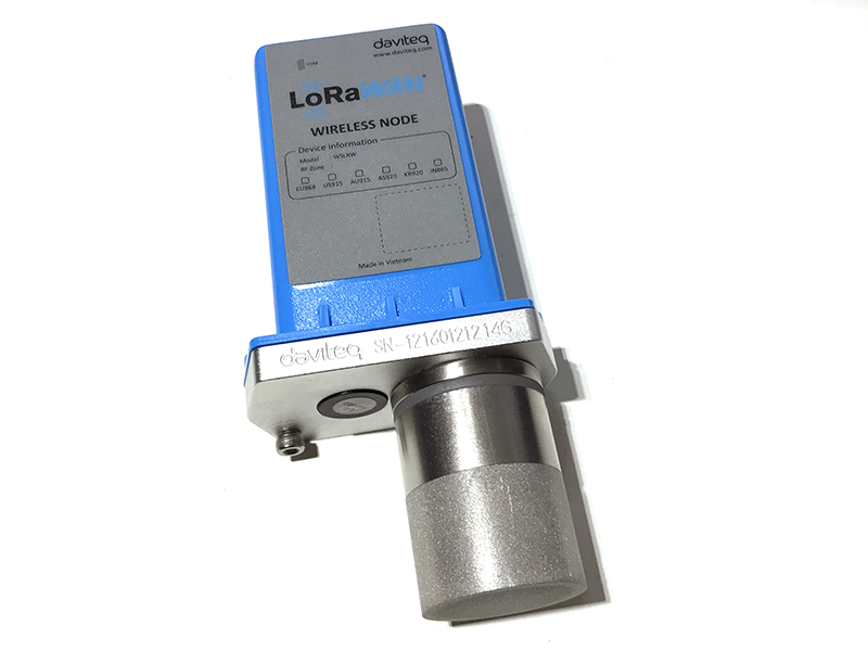
Note for Outdoor installation: For outdoor installation, please use the Rain guard to protect the sensor from raindrops or snowflakes. Please find below the steps of installation
|
Step 1. Prepare the rain guard.
|
Step 2. Insert rain guard to the sensor filter and tighten the locking screws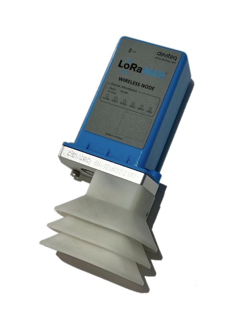 |
6. Troubleshooting for the Daviteq G4 Gas Sensor
| No. | Phenomena | Reason | Solutions | |
| 1 | The measured value is not within the expected value. | 1.1 | The sensor is drifted by time. | Re-calibrate the sensor |
| 1.2 | The sensor was in a high humidity environment (> 90% RH) for more than 03 days continuously. | Place the sensor in low humidity for its recovery. It may take up to 30 days to recover. If the sensor cannot recover after 30 days, please replace the new sensor module. | ||
| 2 | The measured value is always zero or near zero. | 2.1 | The sensor module was removed. | Please check the sensor. |
| 2.2 | The sensor is at the end of its life. | Replace the sensor module | ||
| 3 | HW_Error = 1 | 3.1 | Loosed connection of sensor module and wireless transmitter. | Check the internal wiring. |
| 3.2 | The measuring module got a problem. | Please consult the manufacturer for a warranty or replacement. |
7. Maintenance of the Daviteq G4 Gas Sensor
| What? |
How? |
When? |
| Cleaning the Filter |
Check and clean the filter every few months, depending on the environment. Clean the filter with warm water and soap, then use compressed air to purge it from the inside out. |
Approx. 6-12 months |
| Re-calibration |
The gas sensor may be drifting over time. Please check the sensor specification to identify the interval time for the re-calibration sensor. Please follow the calibration procedure in section 3 above. |
Approx. 6-12 months |
| Sensor replacement |
Replace the new sensor module after 02 years of operation (please check the sensor specification of each gas type). Please see below instructions. |
Approx. 2 years |
Sensor replacement instructions:
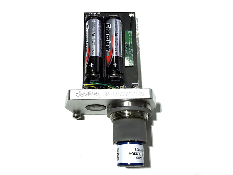
* Please remove the batteries before doing the following steps
|
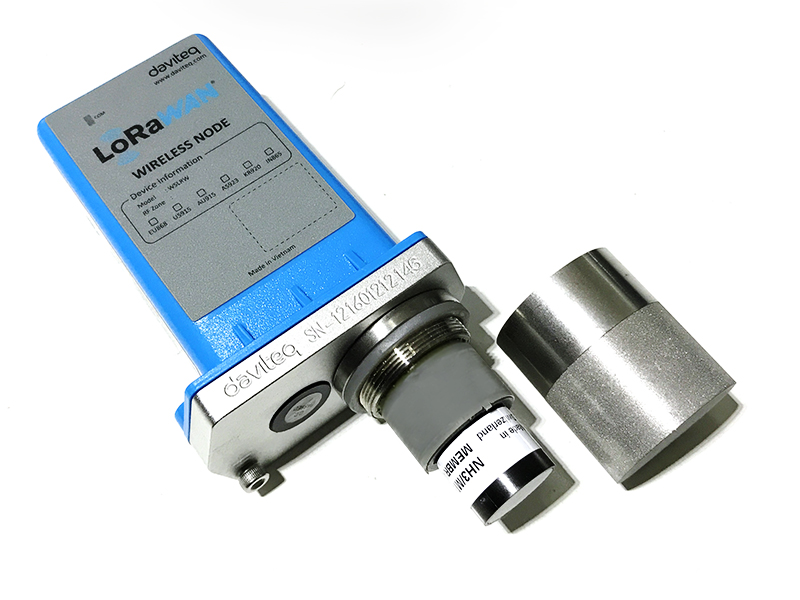
Step 1. Remove the filter
|
Step 2. Unplug the sensor module
|
|
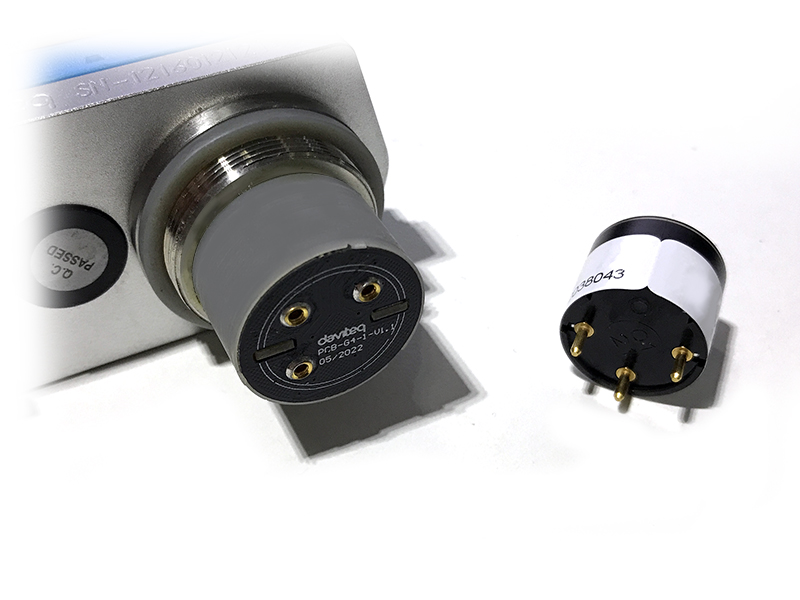
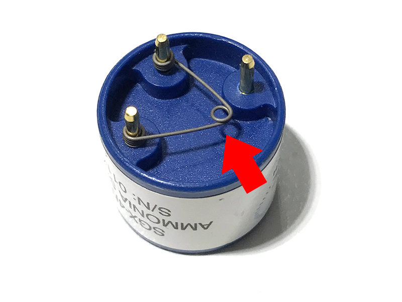
Step 3. Remove the spring clip on the new sensor module.
|
Step 4. Plug the new sensor module into the PCB
|
|
Step 5. Insert the batteries and start calibration of the new sensor as per section 3.
|
Step 6. Place the filter back.
|
8. Default configuration
This G4 gas sensor module has the default configuration, however, those parameters can be changed. The user can change the configuration on the wireless transmitter so that the complete sensor (transducer + wireless) delivers the proper output value. Below are some configuration parameters that store in the flash memory of the wireless transmitter.
| Description | Unit | Default | Format | Property | Comment |
| CONSTANT_A | 1 | Float | R/W |
Constant a for scaling measured value |
|
| CONSTANT_B | 0 | Float | R/W |
Constant b for scaling measured value |
|
| HIGH_CUT | 1E+09 | Float | R/W |
High cut value for scaled_value |
|
| LOW_CUT | 0 | Float | R/W |
Low cut value for scaled_value |
|
| SENSOR+AMPLIFIER SENSITIVITY | mV | Float | R/W |
Default = 11 for NH3 gas sensor |
END.
No Comments