USER GUIDE FOR WIRELESS PT100 TEMPERATURE SENSOR WS433-PT100
| WS433-PT100 |
FEB-2020 |
This document is applied for the following products
| SKU |
WS433-PT100 |
HW Ver. | FW Ver. | ||
| Item Code | WS433-PT100-01 | Wireless PT100 Temperature Sensor 433MHz, Internal antenna, Type AA battery 1.5VDC, IP67 | |||
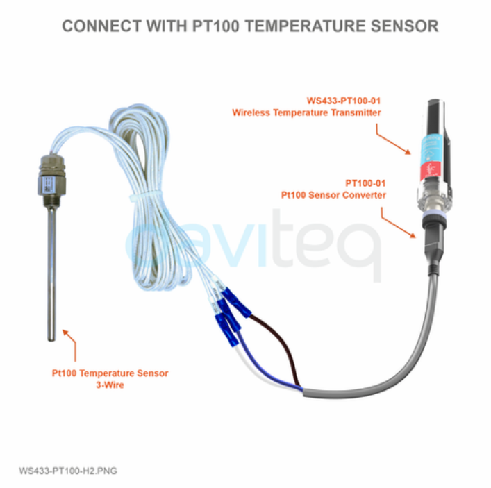
| PT100-01 | Pt100 Sensor Converter 0.5m length with M12-Male connector | ||||
| Notes | * Purchase Pt100 Sensor Converter to connect Pt100 with Wireless Sensor | ||||
Functions Change Log
| HW Ver. | FW Ver. | Release Date | Functions Change |
| 2.5 | 5.04 | NOV-2019 |
|
1. QUICK INSTALLATION GUIDE
1.1. Introduction
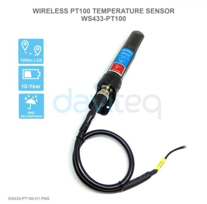
Wireless PT100 Temperature Sensor WS433-PT100 is wireless sensor with modular design connected to PT100 temperature sensor via PT100 sensor converter cable with M12 connector, it utilizes Digital temperature sensor delivers high accuracy measurement in range 0∼100℃. The wireless transmitter is Sub-GHz technology from Texas Instruments allows long range transmission at ultra-low power consumption. It will connect 2-way wirelessly to the wireless co-ordinator WS433-CL to send data and receiving the configuration. It can be configured the operation parameters like data sending interval, health check cycle... remotely from Globiots platform or via ModbusRTU software (thru the WS433-CL). Its default data rate is 50kbps, can be switched to 625bps to increase the communication range. It can last up to 10 years with a single AA battery. There are a lot of applications as environment monitoring for factories, agriculture, boilers, ..
How the sensor connect to system?
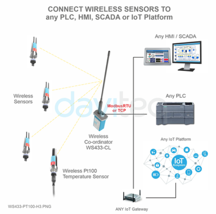
Below is the Sub-GHz system architecture:
System components:
1. Wireless sensors are Sub-GHz Sensors
2. WS433-CL is a wireless co-ordinator in a wireless sensor network.
3. PLC, HMI, SCADA or IoT Platform
How to set up the LoRaWAN system? Please follow these steps:
1. Connect PT100 temperature sensor to WS433-PT100.
2. Add sensors node to Co-ordinator WS433-CL.
3. Read sensor's data from Co-ordinator WS433-CL by Daviteq Modbus Configuration Tool.
4. Connect the Co-ordinator WS433-CL to PLC, HMI, SCADA or IoT Platform.
1.2 Application Notes
| For Applications | Temperature Monitoring, Process Monitoring, Safety Monitoring |
| Notes |
When selecting a Pt100 transmitter node, consider the following criteria: - Temperature Range: Determine the required measurement temperature range for your application. - Chemical Resistance: Assess the compatibility and durability of the Pt100 wires with the environment where they will be exposed. - Abrasion and Vibration Resistance: Choose a transmitter that can withstand abrasion and vibration in your specific installation. - Installation Requirements: Consider existing equipment and available probe hole sizes to determine the appropriate probe diameter |
1.3 When does device send messages to Co-ordinator WS433-CL?
The device will send uplink messages in the following cases:
Case 1: Every time interval of Cycle_wakeup, sensor node would ONLY send data to co-ordinator if the new measured value was changed more than the Delta value of the last measured value. Default Cycle_wakeup is 120 seconds and Default Delta value is 0.
Case 2: Every time interval of Cycle_healthsta, sensor node will absolutely send data to co-ordinator regardless any condition. Default Cycle_healthsta is 120 seconds
1.4 Default Configuration
Pt100 transmitter has the default configuration. The user can change the configuration on the wireless transmitter so that the complete sensor (transducer + wireless) delivers the proper output value.
1.5 Battery/ Power Supply
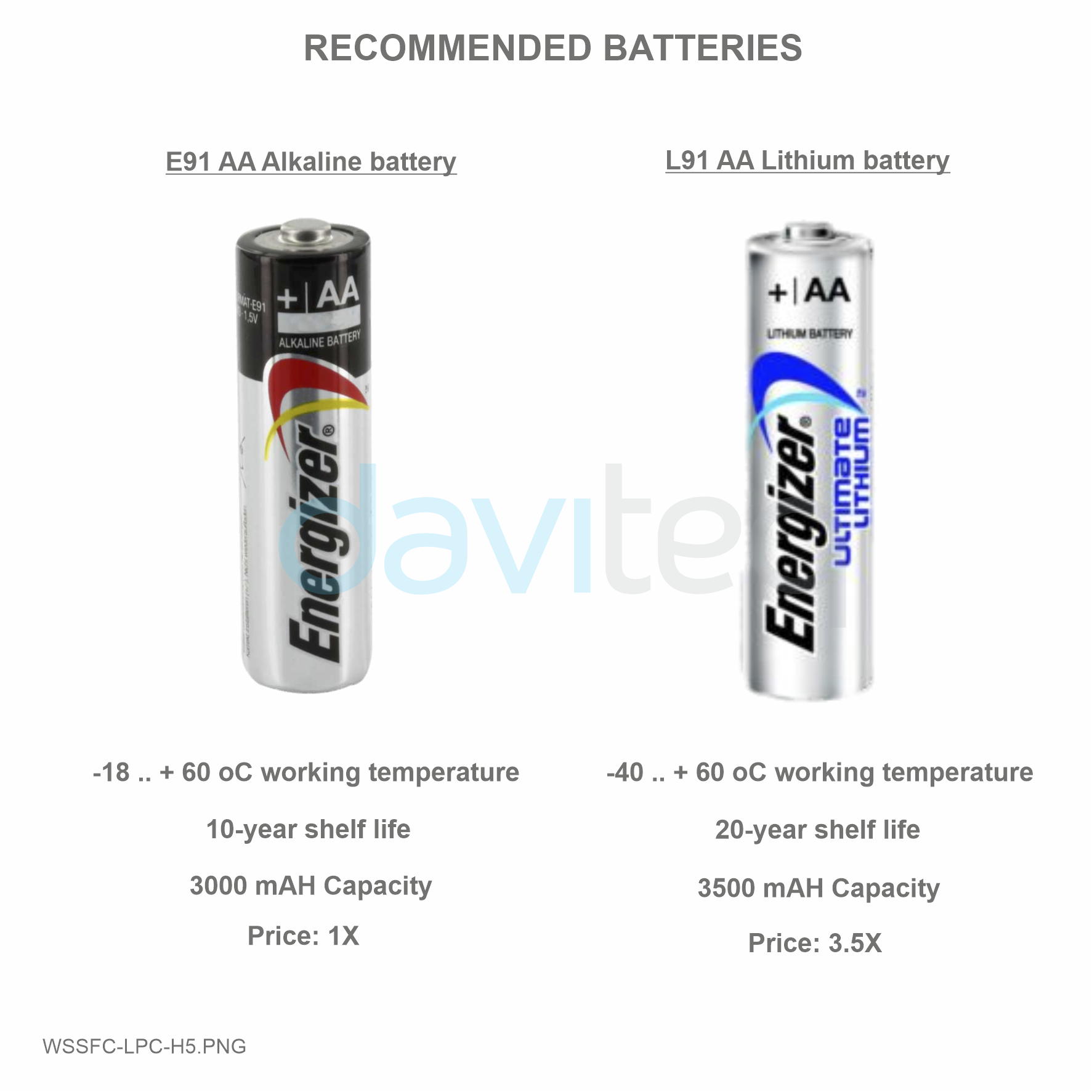
The Device uses below batteries:
-
Battery type: Primary battery
-
Battery size and Voltage: AA 1.5 VDC
-
Number of batteries: 01
-
Recommended batteries: Energizer® L91 or equivalent from Duracell;
1.6 What's in the Package?
1.7 Guide for Quick Test
Step 1: Power up the Co-ordinator WS433-CL
After powering up the Co-ordinator via M12 connector, the Sub-GHz sensors must be registered within the first 5 minutes.
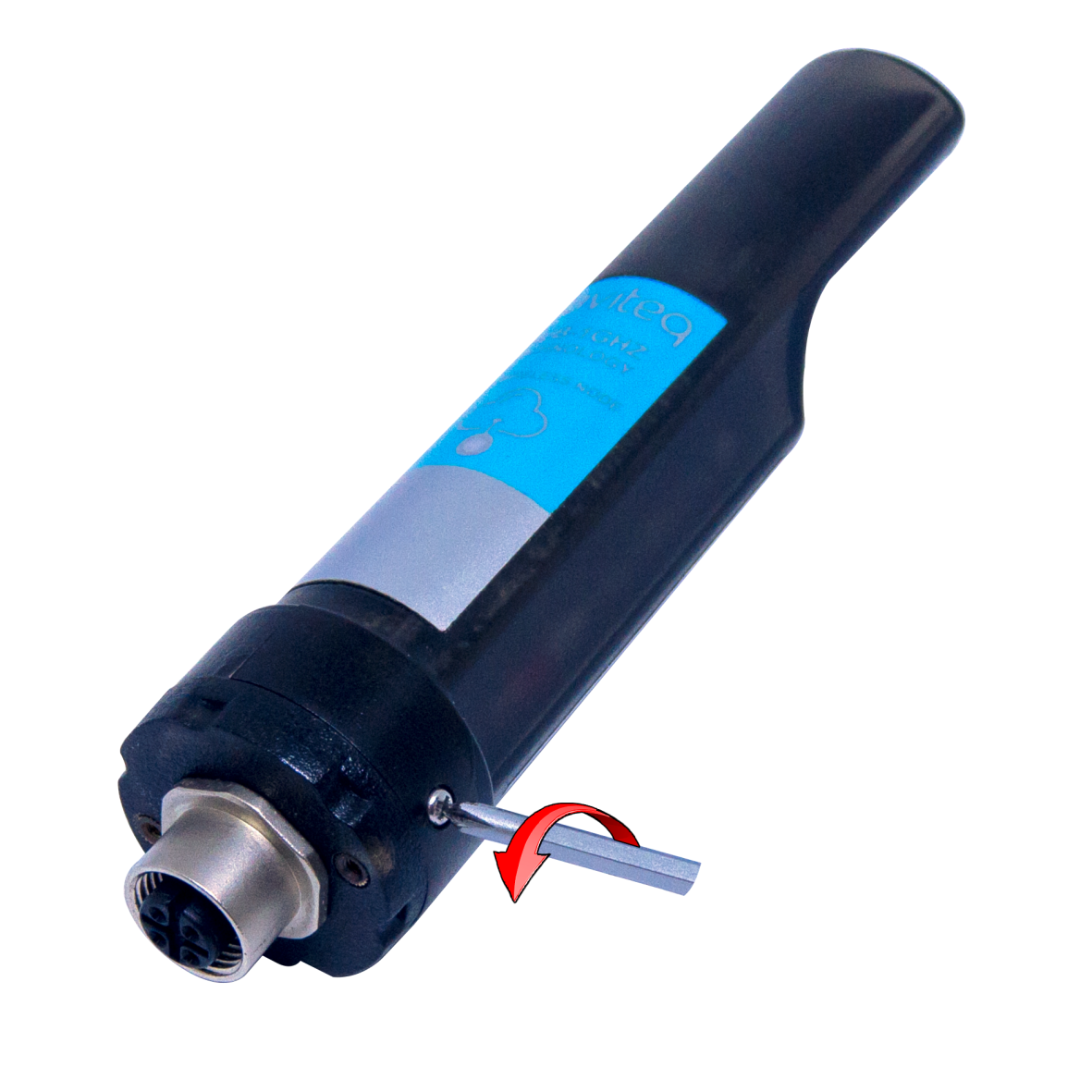
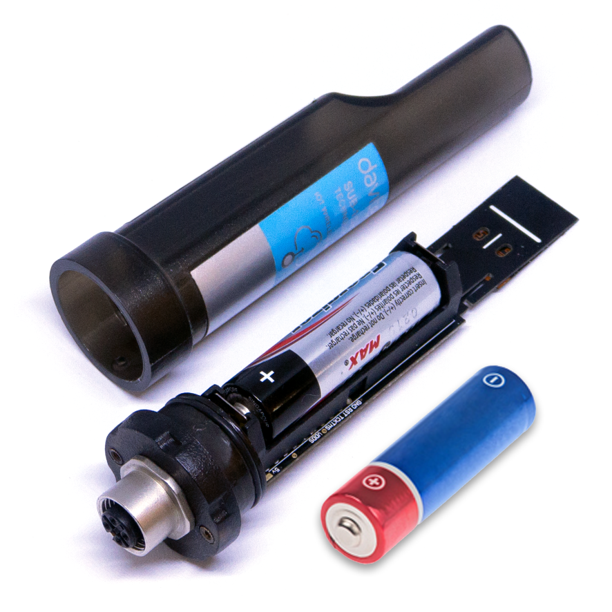
Step 2: Insert the batteries to the wireless sensor, then touch the sensor to Co-ordinator's antenna.
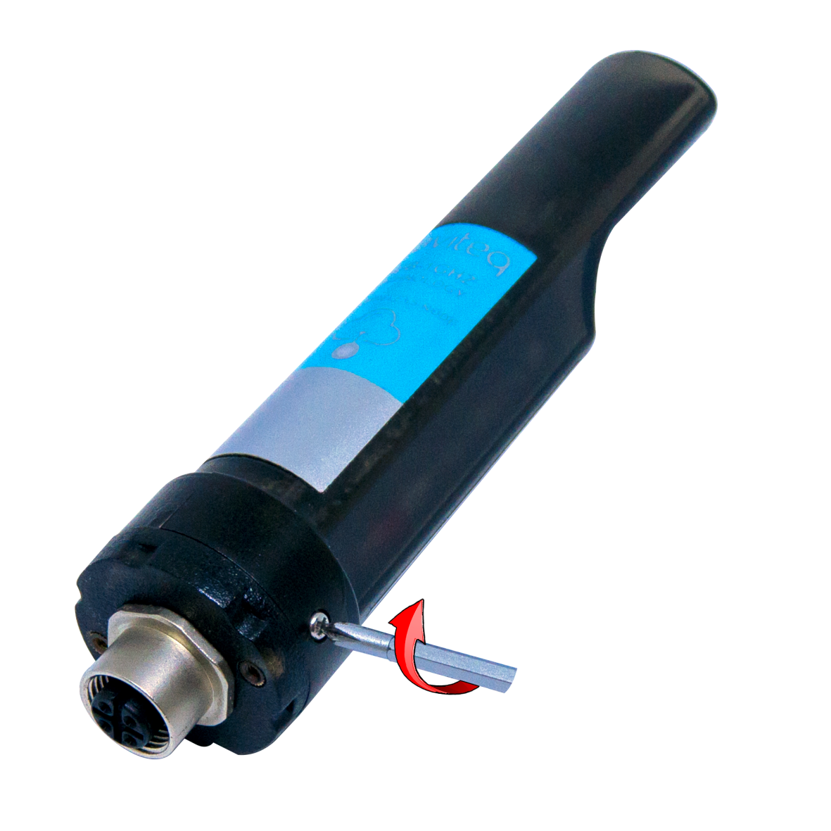
- Using Philips screw driver to unscrew M2 screw at the side of housing
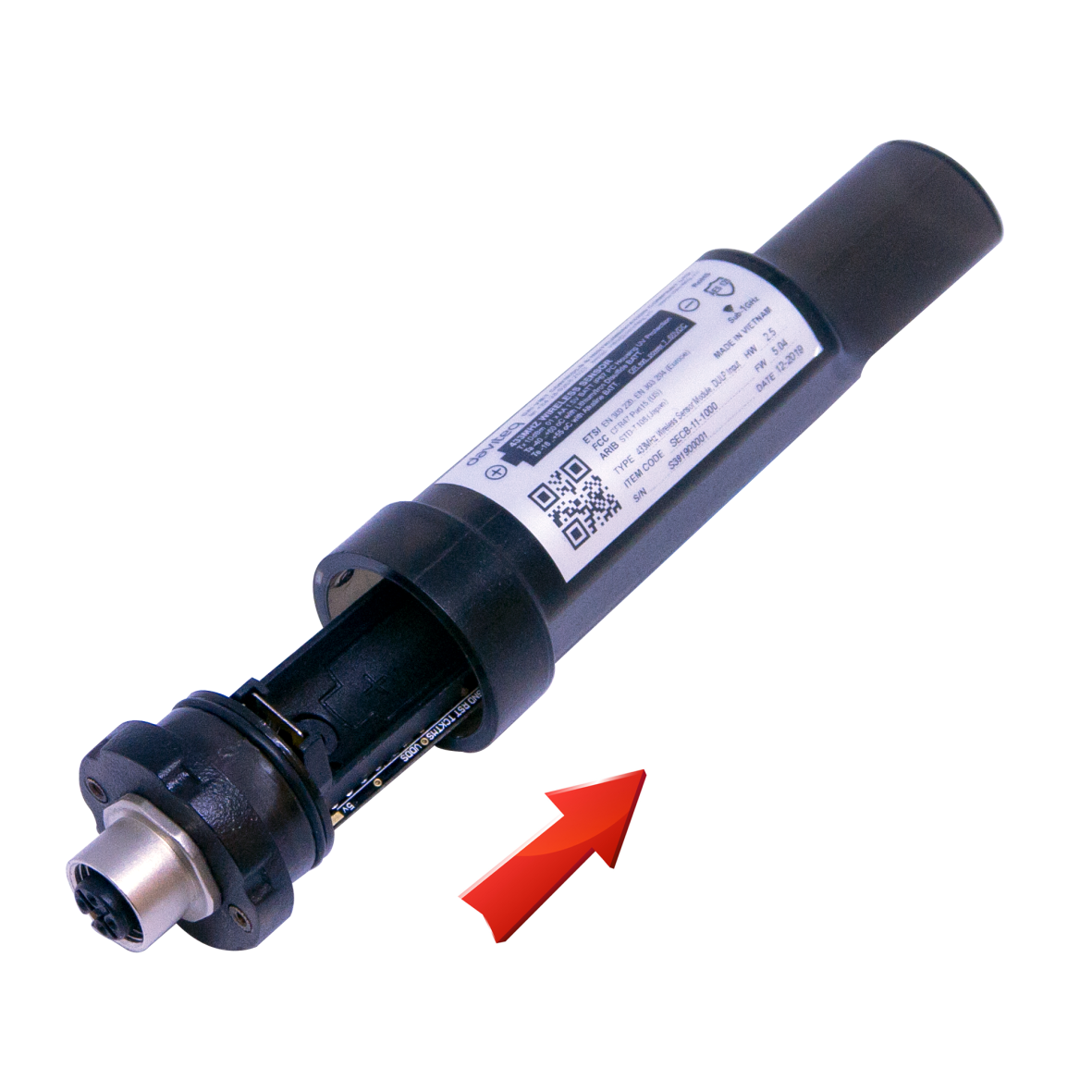
- Carefully pull out the top plastic housing in the vertical direction
NOTE: Because of O-ring, it requires to have much pulling force at the beginning, therefore please do it carefully to avoid the damage of circuit board which is very thin (1.00mm);
- Insert the AA battery, please take note the poles of battery
- Insert the top plastic housing and locking by M2 screw
- Buzzer sounds 1 beep sound, LED blink 1 time, that means registering Node ID on Co-ordinator successfully.
- Buzzer sounds 2 beep sounds, LED blink 2 times, that this Node ID is already registered.
If the buzzer does not sound, take off the batteries from the wireless sensor, wait for 5s then insert the batteries again. After that, touch the sensor to Co-ordinator's antenna.
Step 3: Read sensor's data via Daviteq Modbus Configuration Tool software
Configure the wireless sensor with the co-ordinator by following the steps in the link below:
1.8 Installation
Dimension Drawings and Installation Gallery (Photos and Videos)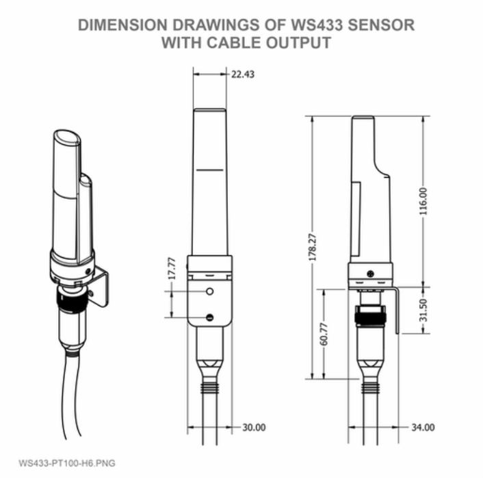
Installation Notes for Sensor Part (if available)
Some key points to consider when installing a PT100 transmitter:
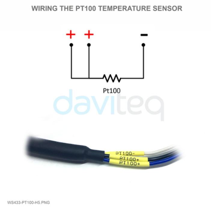
1. Wiring Configuration:
- Three-Wire Configuration: Most common, compensates for lead wire resistance, improving accuracy.
2. Connection Steps:
- Connect the PT100 Sensor: Ensure the sensor is properly connected to the transmitter.
- Power Supply: Verify that the transmitter is connected to the appropriate power supply as specified in the manual.
- Configuration: Use the manufacturer's software or tools or online downlink to configure the transmitter settings. This may involve setting the range, calibration, and other parameters
3. Installation Environment:
- Temperature: Ensure the installation environment is within the operating temperature range of the transmitter.
- Protection: If the transmitter is installed in a harsh environment, consider using protective enclosures to shield it from dust, moisture, and other contaminants.
4. Calibration:
- Initial Calibration: Perform an initial calibration after installation to ensure accurate readings.
- Regular Maintenance: Schedule regular maintenance and recalibration to maintain accuracy over time.
Installation Guide for Main Device
Check the Location for the best RF Signal
Make sure the site is good enough for RF signal transmission.
Tip: To maximize the transmission distance, the ideal condition is Line-of-sight (LOS) between the LoRaWAN sensor and the gateway. In real life, there may be no LOS condition. However, the LoRaWAN sensor still communicates with the gateway, but the distance will be reduced significantly.
Connect the external Pt100 sensor to Device and install the Device on the Wall/Housing/Structure
Placing the wireless module on bracket and secure it by 02 x M2 screws (supplied in accessory bag)
Note: The bracket can be mounted on the wireless module in both direction, upward or downward
The mounting bracket is made from hard metallic material. The following steps are for mounting this bracket;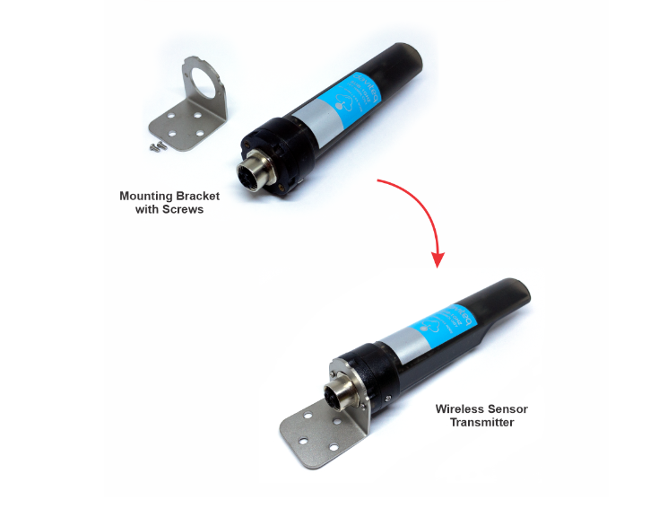
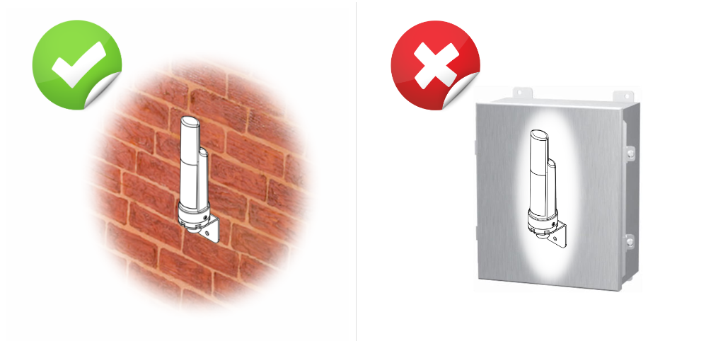
DO NOT install the wireless sensor or its antenna inside a completed metallic box or housing because the RF signal can not pass through the metallic wall. The housing is made from Non-metallic materials like plastic, glass, wood, leather, concrete, and cement…is acceptable.
1.9 Memory map resgisters
Memmap resgisters
Download Modbus Memmap of WS433-CL with the following link:
https://filerun.daviteq.com/wl/?id=BKEaUzdArkoc0Hc7nfpRShdPVToVrqQZ
2. MAINTENANCE
2.1 Troubleshooting
Please find below steps to identify the problems from Communication Part or Sensor Part:
* If the device cannot connect to the Gateway or System or Co-ordinator at the first time, it is the Communication Problem.
* If the device status like battery, RSSI level, data status or other communication is normal, but the measured values are not updated or wrong, it would be the problems of Sensor part;
* If the data coming to gateway, system or co-ordinator is not frequently as expected, the problem would be Communication.
Please refer below the troubleshooting guide
| No. | Phenomena | Reason | Solutions |
| 1 | The status LED of wireless sensor doesn't light up |
|
|
| 2 | Wireless sensor not connected to co-ordinator |
|
|
2.2 Maintenance
Maintenance for Main device
There is no requirement for maintenance of the Hardware of LoRaWAN device except:
- The battery needs to be replaced. Please check the battery status via uplink messages;
Note: When the battery indicator shows only one bar (or 10% remaining capacity), please arrange to replace the battery with a new one as soon as possible. If not, the battery will drain completely, and the resulting chemical leakage can cause severe problems with the electronic circuit board.
- Sensor, please refer to the maintenance section of the sensor document.
Maintenance for Sensor part (if available)
- Regular Calibration:
- Initial Calibration: Perform an initial calibration after installation.
- Periodic Calibration: Schedule regular calibration intervals based on the manufacturer's recommendations and the operational environment.
- Visual Inspection:
- Check Connections: Ensure all electrical connections are secure and free from corrosion.
- Inspect Wiring: Look for any signs of wear or damage to the wiring.
- Functional Testing:
- Simulate Sensor Inputs: Use a decade resistance box for RTDs to simulate sensor inputs and verify transmitter output.
- Check Output: Compare the transmitter output with the expected values to ensure accuracy.
- Environmental Considerations:
- Protective Enclosures: Ensure the transmitter is housed in a suitable enclosure to protect it from dust, moisture, and other environmental factors.
- Temperature Range: Verify that the transmitter is operating within its specified temperature range.
- Documentation:
- Record Keeping: Maintain detailed records of all maintenance activities, including calibration results and any adjustments made.
- Update Labels: After maintenance, update calibration stickers and labels on the transmitter.
- Safety Precautions:
- Personal Protective Equipment (PPE): Always wear appropriate PPE during maintenance.
- Work Permits: Obtain necessary work permits and approvals before starting maintenance.
3. ADVANCED GUIDE
3.1 Principle of Operation
When the sensor sampling time interval is reached, For example 2 minutes, the node will wake up and switch ON the power supply to supply the energy to external sensor to start the measurement. Depends on the type and characteristic of external sensor, the sensor will take a certain time to finish the measurement.
For example: the measurement time is 200mS, after this time, the node will read the value of sensor, node will switch OFF power supply to external sensor to save energy.
The measured value is the raw value of the sensor. The measured value can be scaled according to the following formula:
Y = aX + b
-
-
-
-
- X: the raw value from the sensor
- Y: the calculated value for parameter 1's value or parameter 2's value
- a: constant (default value is 1)
- b: constant (default value is 0)
-
-
-
So, if there is no user setting for a and b ==> Y = X
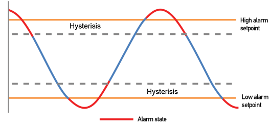
The Y value will be compared with Lo and Hi threshold. Please refer below the graph of alarm processing.
Status bytes of sensor Node
- Hi-Byte is error code
| Error code | Description |
| 0 | No error |
| 1 | Just exchange the sensor module but node has not been reset ==> please take out the battery for 20s then install it again to reset node to recognize the new sensor module |
| 2 | Error, sensor port M12F shorted to GND |
| 3 | Error, sensor port M12F shorted to Vcc |
| 4 | Error, sensor port M12F shorted each other |
- Lo-Byte is sensor type
| Error code | Description |
| 0 | No error |
| 1 | Just exchange the sensor module but node has not been reset ==> please take out the battery for 20s then install it again to reset node to recognize the new sensor module |
| 2 | Error, sensor port M12F shorted to GND |
| 3 | Error, sensor port M12F shorted to Vcc |
| 4 | Error, sensor port M12F shorted each other |
Logic status of parameters
- Hi-Byte is Logic status of parameter 1
- If parameter 1's value > high threshold 1 => Hi-Byte of Logic status = 1
- If parameter 1's value < low threshold 1 => Hi-Byte of Logic status = 0
- If parameter 1 is digital => Hi-Byte of Logic status = parameter 1's value
- Timer up 1 = (Total time when Hi-Byte of Logic status = 1)
- Timer down 1 = (Total time when Hi-Byte of Logic status = 0)
- RisingEdge counter 1 = (Counter value when Hi-Byte of Logic status changes from 0 to 1)
- FallingEdge counter 1 = (Counter value when Hi-Byte of Logic status changes from 1 to 0)
- Lo-Byte is Logic status of parameter 2
- If parameter 2's value > high threshold 2 => Lo-Byte of Logic status = 1
- If parameter 2's value < low threshold 2 => Lo-Byte of Logic status = 0
- If parameter 2 is digital => Lo-Byte of Logic status = parameter 2's value
- Timer up 2 = (Total time when Lo-Byte of Logic status = 1)
- Timer down 2 = (Total time when Lo-Byte of Logic status = 0)
- RisingEdge counter 2 = (Counter value when Lo-Byte of Logic status changes from 0 to 1)
- FallingEdge counter 2 = (Counter value when Lo-Byte of Logic status changes from 1 to 0)
3.2 Configuration
3.2.1 Reset Sensor Node
Step 1: Using Philips screw driver to unscrew M2 screw at the side of housing and carefully pull out the top plastic housing in the vertical direction.
Step 2: Press the button until you see LED flashes 3 times to reset
3.2.2 Data rate configuration 625 kps
Take off the sensor cover like Step 1 and press the button until you see LED flashes 2 times for 625 kps option
3.2.3 Wireless sensor configuration with co-ordinator
Configure the wireless sensor with the co-ordinator by following the steps in the link below:
4. PRODUCT SPECIFICATIONS
4.1 Specifications
| Input | PT100 Temperature Sensor |
| Accuracy | 0.05% |
| Sensor port connector | M12-Female Connector |
| Accessories | Pt100 sensor converter cable 0.5m length with M12-Male connector (not include) |
| Data speed | Up to 50kbps |
| Tranmission distance, LOS | 500m |
| Antenna | Internal Antenna, 3 dbi |
| Battery | 01 x AA 1.5VDC, up to 10-year operation, depends on configuration |
| Frequency Band | ISM 433MHz, Sub-GHz technology from Texas Instrument, USA |
| International Compliance | ETSI EN 300 220, EN 303 204 (Europe) FCC CFR47 Part15 (US), ARIB STD-T108 (Japan) |
| Security Standard | AES-128 |
| Operating temperature of PCB | -40∼60℃ (with AA L91 Energizer®) |
| Housing | Poly-carbonate, IP67 |
| Installation method | L-type bracket SUS304 , by M4 screws or double-sided 3M tape (included) |
| Product dimensions | 125x30x30mm |
| Net weight (without battery) | < 60g |
| Box dimension | 190x50x50mm |
| Gross weight | 100g |
5. WARRANTY & SUPPORT
5.1 Warranty
Warranty
Below terms and conditions are applied for products manufactured and supplied by Daviteq Technologies Inc.
Free Warranty Conditions
-
The manufacturer undertakes to guarantee within 12 months from shipment date.
-
Product failed due to defects in material or workmanship.
-
Serial number, label, warranty stamp remains intact (not purged, detected, edited, scraped, tore, blurry, spotty, or pasted on top by certain items).
-
During the warranty period, if any problem of damage occurs due to technical manufacturing, please notify our Support Center for free warranty consultancy. Unauthorized treatments and modifications are not allowed.
-
Product failed due to the defects from the manufacturer, depending on the actual situation, Daviteq will consider replacement or repairs.
Note: One way shipping cost to the Return center shall be paid by Customers.
Paid Warranty
-
The warranty period has expired.
-
The product is not manufactured by Daviteq.
-
Product failed due to damage caused by disasters such as fire, flood, lightning or explosion, etc.
-
Product damaged during shipment.
-
Product damaged due to faulty installation, usage, or power supply.
-
Product damage caused by the customer.
-
Product rusted, stained by effects of the environment or due to vandalism, liquid (acids, chemicals, etc.)
-
Product damage is caused by unauthorized treatments and modifications.
Note: Customers will be subjected to all repairing expenses and 2-way shipping costs. If arises disagreement with the company's determining faults, both parties will have a third party inspection appraise such damage and its decision be and is the final decision.
5.2 Support
Support via Help center
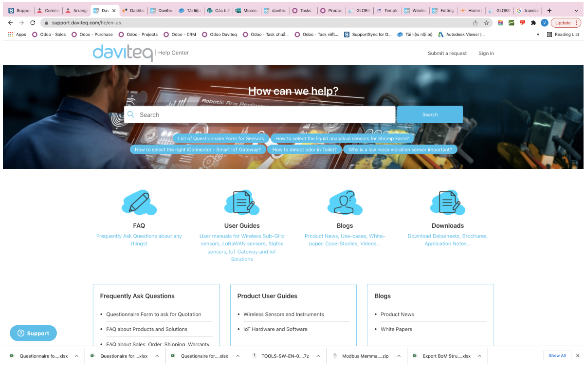
For support, please contact our support center at the following link: https://support.daviteq.com/hc/en-us
-
If you have any questions about the product, you can search for information on that page;
-
If you can't find the right information, please register an account and send us a request. We will respond within 24 hours;
-
Our support engineer will contact you via the Ticket system. If the product needs to be sent back to the factory for warranty, we will generate an RMA code so you can send it back to us. To follow the status of the RMA process, customers can visit our SupportSync system as below.
|
Manufacturer Daviteq Technologies Inc Email: info@daviteq.com | www.daviteq.com
|
Distributor in Australia and New Zealand Templogger Pty Ltd Tel: 1800 LOGGER Email: contact@templogger.net |



No Comments