III. ADVANCE GUIDE
3.1 Principle of Operation
3.1.1 LED meaning
3.1.1.1 LED status
| Status | Meaning |
| Fixed ON | iConnector has been supplied with external power |
| Blinking (4 seconds blink 1 time) | Without external power, iConnector is using battery. |
| Blinking (2 seconds blink 1 time) | Low battery warning (Used for type D battery version) |
3.1.1.2 LED modbus
| Status | Meaning |
| Fixed ON | Modbus connected |
| Blinking (1 seconds blink 2 time) | Connection errors (wrong configuration of baudrate, noise, …) |
| OFF | No modbus connection |
3.1.1.3 LED network
| Status | Meaning |
| Blinking (1s change state) | Connecting with Globiots |
| Blinking (2s change state) | Initializing wifi generator, waiting for configuration via phone or modbus tool (For iConnector wifi) |
| OFF/Blinking (2s change state) | No connection with Globiots |
3.1.2 Memory Map
|
Address |
Size (bytes) |
Memory type |
Read/Write |
Description |
|
0-0x1FFF |
8096 |
FLASH |
R/W |
Save active configuration, do not allow log, realtime. |
|
0x2000-0x22FF |
768 |
RAM |
R |
Save data read from modbus slaves. |
|
0x2300-0x24FF |
512 |
RAM |
R |
The intrinsic data of iConnector |
|
0x3000-0x30FF |
256 |
RAM |
R/W |
|
|
0x5000-0x50FF |
256 |
FLASH |
R/W |
|
|
0x6000-0x6FFF |
4096 |
RAM |
R |
Save data read from modbus slaves |
- Data address area: 0x2000-0x22FF (768 bytes), and 0x6000-0x6FFF (4096 bytes).
- Controller address area: 0x3000-0x30FF (256 bytes, without flash storage), and 0x5000-0x50FF (256 bytes, with flash storage).
Address area 0x5000-0x50FF
- 256 bytes;
- Save in flash (when power is lost, will keep the same value);
- Allows reading, and writing from Globiots;
- Allow log (realtime);
- Allows Modbus write to Slaves;
- It is not allowed to store data read from Modbus Slaves.
NOTE: Flash recorded about 100,000 times will be damaged so do not use this area to contain the value is changed several times.
3.1.3 Logged data
- Up to 20 different log cycles;
- 320 log parameters maximum for all log cycles.
- Up to 120 log parameters per log cycle.
3.1.4 Modbus
- Support modbus RTU.
- Address slave 1… 247.
- It is not allowed to set address slave = 0.
- Baudrate 4800/9600/19200.
- Parity none / odd / even.
- Up to 100 modbus instructions.
- The address area for storing read data: 0x2000-0x22FF (768 bytes), and 0x6000-0x6FFF (4096 bytes).
- Controller address area: 0x3000-0x30FF (256 bytes, without flash storage), and 0x5000-0x50FF (256 bytes, with flash storage).
3.1.5 Realtime
- Read up to 200 parameters.
- If all parameters are float (4 bytes) then read up to 140 parameters.
- The fastest realtime sending frequency is 1 second.
- Up to 28 alarms.
- Supported data types:
|
PrmType |
Description |
# Byte |
Range |
|
1 |
BYTE |
1 |
0 to 255 |
|
2 |
UINT16 |
2 |
0 to 65,535 |
|
3 |
UINT32 |
4 |
0 to 4,294,967,295 |
|
4 |
FLOAT |
4 |
-/+3.40282347 * (10^+38) |
|
5 |
INT16 |
2 |
-32,768 to 32,767 |
|
6 |
INT32 |
4 |
-2,147,483,648 to 2,147,483,647 |
3.1.7 Event
- The event table is 1024 bytes.
- The number of events depends on the short length of the event configured.
- Supported data types:
|
PrmType |
Description |
# Byte |
Range |
|
1 |
BYTE |
1 |
0 to 255 |
|
2 |
UINT16 |
2 |
0 to 65,535 |
|
3 |
UINT32 |
4 |
0 to 4,294,967,295 |
|
4 |
FLOAT |
4 |
-/+3.40282347 * (10^+38) |
|
5 |
INT16 |
2 |
-32,768 to 32,767 |
|
6 |
INT32 |
4 |
-2,147,483,648 to 2,147,483,647 |
3.1.8 Health data
- Every 15 seconds send health pack 1 time.
3.2 Configuration
3.2.1 Online configuration from Globiots
Refer section 5. Configure Device of the Globiots manual in the link to get the instruction of configurating the iConnector in Globiots
3.2.2 Offline configuration
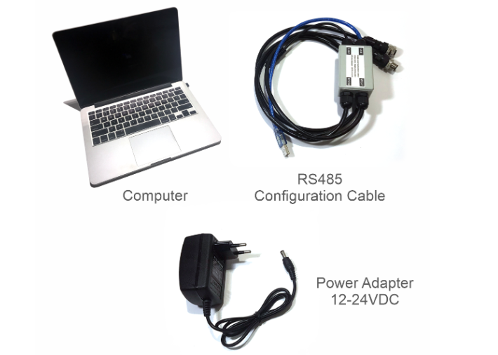
Step 1: Preparation
Prepare some required devices as below
01x A window PC
01x USB-RS485 Configuration Cable
01x Power adapter 12-24VDC
Download the Configuation software in the link
Step 2: Hardware connection
- Connect the USB-A to the PC
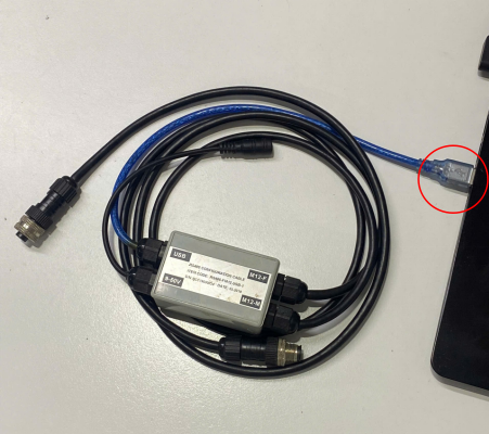
- Connect M12 female of the cable to the iConnector

- Power the iConnector on by connecting DC jack from Power Adapter
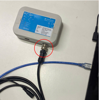
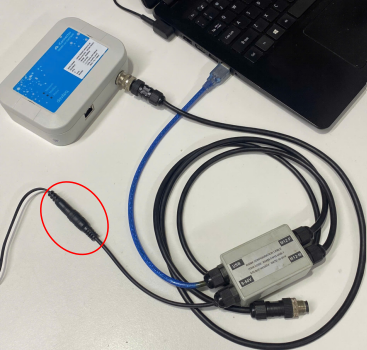
The above steps must be performed in order
Step 3: Configuration the iConnector via iConfig software
- Open the iConfig software, then choose Correct Port, BaudRate and Parity.
Port is based on the PC
BaudRate is 9600
Parity is NONE
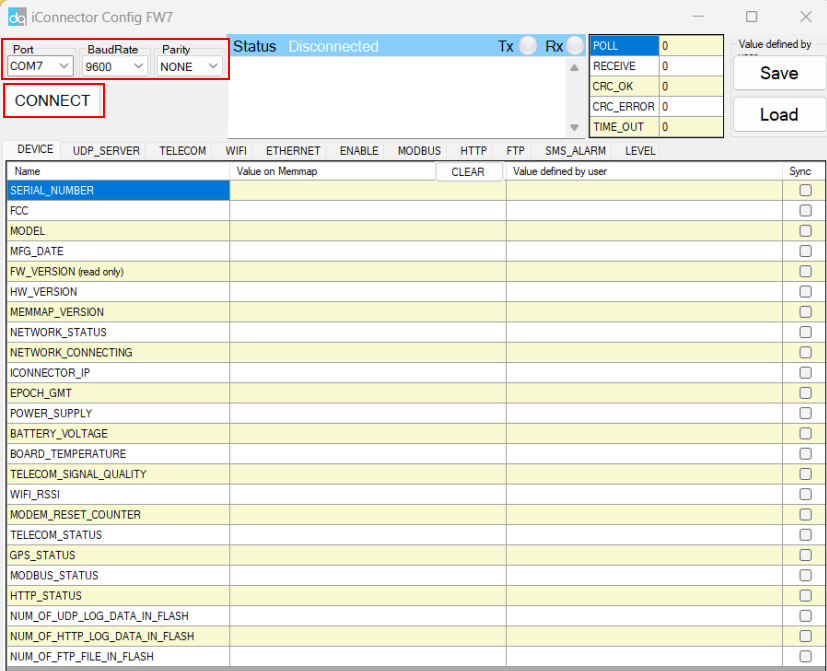

(1) There are 11 configuration tabs on the top banner. Click a tab name to navigate to the corresponding sheet.
(2) The first column displays the parameter names of the iConnector.
(3) The second column shows the current values of the corresponding parameters
(4) The third column is where users can input new configuration values.
(5) After entering the new configuration in the third column, users must tick the corresponding checkbox to apply it. The tick will disappear once the new configuration is successfully written to the iConnector. After that, the updated value will appear in the second column.
No Comments