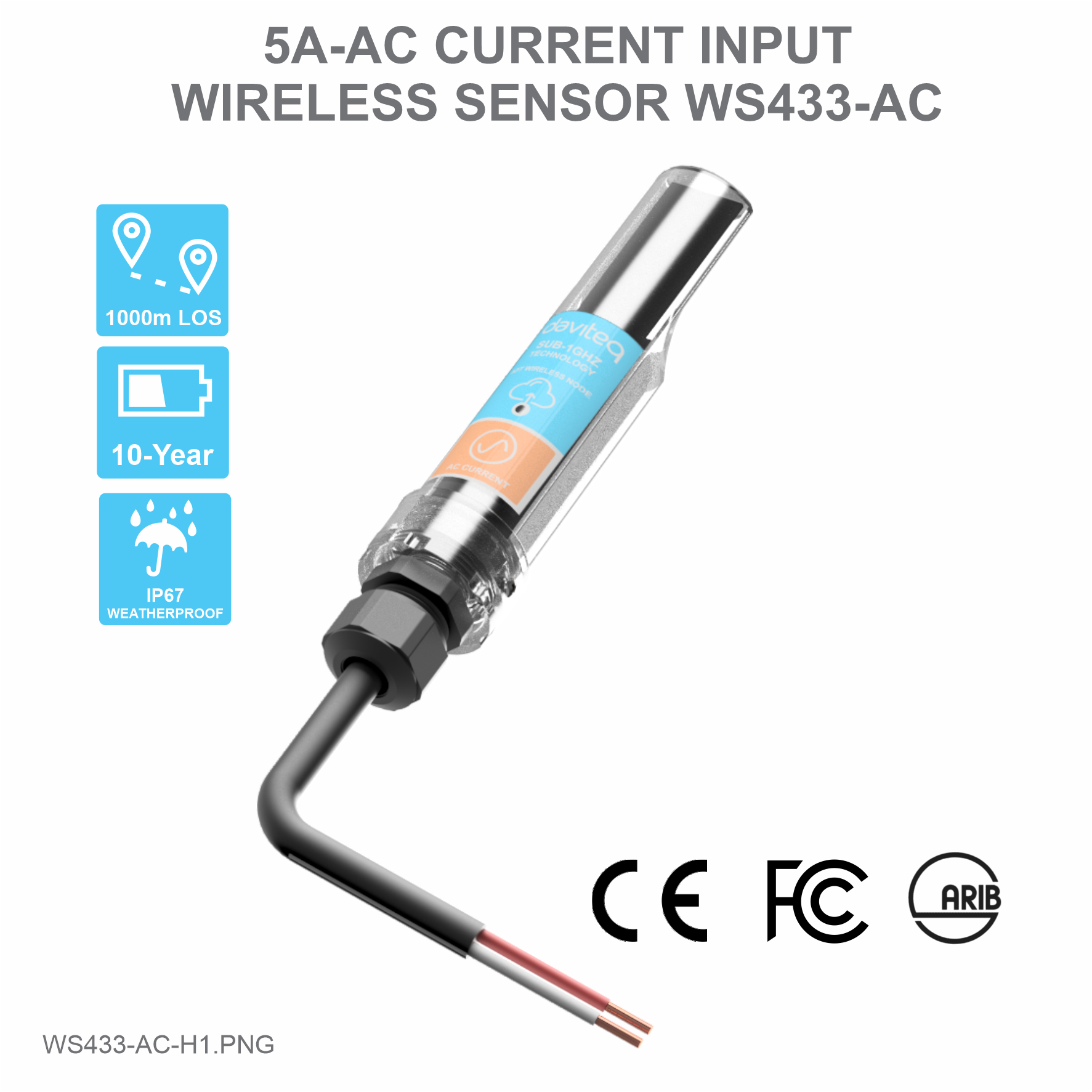
USER GUIDE FOR WIRELESS SENSOR AC CURRENT INPUT WS433-AC
| WS433-AC-MN-EN-01 |
APR-2020 |
This document is applied for the following products
|
SKU |
WS433-AC |
HW Ver. |
2.5 |
FW Ver. |
5.0 |
|
Item Code |
WS433-AC-11 |
Wireless sensor 1-channel AC current input max 5A, IP67, battery AA 1.5VDC, cable 0.5m length with PG9 cable gland and wire crimpping connectors for SAFETY |
|||
1. Functions Change Log
| HW Ver. | FW Ver. | Release Date | Functions Change |
| 2.5 | 5.0 | DEC-2019 |
|
2. Introduction
Wireless sensor with 1-channel AC current input 5A to measure the AC current load of your motors, machines...to count the energy consumption, OVER-load or NO-load detection, run hour counting…It is configured the operation parameters like data sending interval, health check cycle...remotely from Globiots platform or via ModbusRTU software. The wireless module can last up to 10 years with a single AA battery.
3. Specification
| Measuring range | 0..5A AC |
| Accuracy | 1.0% |
| Resolution | 10 bit |
| Temperature Drift | < 100 ppm |
| Electrical connection | cable 0.5m length with PG9 cable gland and wire crimpping connectors for SAFETY |
| Optional accessories | 304SS Adapter PG9/male 1/2""NPT or PG13.5 or M20 to allow direct mounting on Process instruments or electrical panel |
| Data speed | Up to 50kbps |
| Tranmission distance, LOS | 500m |
| Antenna | Internal Antenna, 3 dbi |
| Battery | 01 x AA 1.5VDC, up to 10-year operation, depends on configuration |
| Frequency Band | ISM 433Mhz, Sub-GHz technology from Texas Instrument, USA |
| Receiving Sensitivity | -110dBm at 50kbps |
| International Compliance | ETSI EN 300 220, EN 303 204 (Europe) FCC CFR47 Part15 (US), ARIB STD-T108 (Japan) |
| Security Standard | AES-128 |
| Operating temperature of PCB | -40oC..+60oC (with AA L91 Energizer) |
| Housing | Poly-carbonate, IP67 |
| Installation method | L-type bracket SUS304 , by M4 screws or double-sided 3M tape (included) |
| Product dimensions | 125x30x30mm |
| Net weight (without battery) | < 100g |
| Box dimension | 190x50x50mm |
| Gross weight | 140g |
4. Product Pictures
|
 |
 |
 |
 |
 |
5. Operation Principle
5.1 Add sensors node to Co-ordinator WS433-CL
5.1.1 Add Sensor Node ID automatically
 |
 |
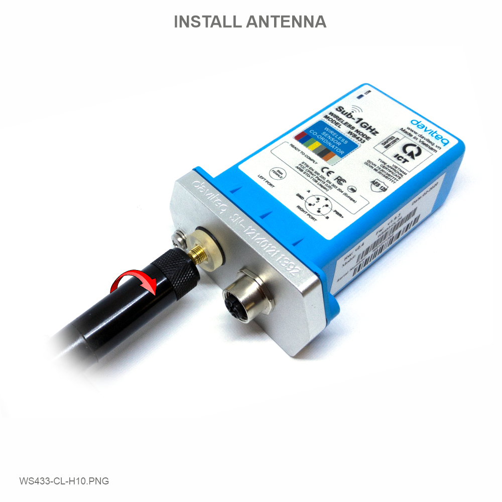
Step 1: After supplying power the Co-ordinator via M12 connector, the Node ID must be registered within the first 5 minutes, up to 40 WS.
Step 2: Bring the wireless sensor closer to the Co-ordinator's antenna then take off the wireless sensor battery, wait for 5s then insert the battery again. If:
- Buzzer plays 1 peep sound, LED blink 1 time, that means registering Node ID on Co-ordinator successfully.
- Buzzer plays 2 peep sounds, LED blink 2 times, that this Node ID is already registered.
If you do not hear the "Peep" sound, please disconnect the power the co-ordinator, wait a few minute and try again.
Node id added in this way will be written to the smallest node_id_n address which is = 0.
Set Rssi_threshold (see RF MODE CONFIG (in the Modbus Memmap of WS433-CL), default -25): The case if Co-ordinator is on high position and need to add node sensor. We set the sensor as close as possible and set the Rssi_threshold to -80, -90 or -100 to increase the sensitivity to allow WS433-CL-04 can add sensors at a longer distance. After that, perform 2 steps of adding sensors and then reset Rssi_threshold = -25.
Enb_auto_add_sensors configuration (see RF MODE CONFIG (in the Modbus Memmap of WS433-CL)): In case you do not want to turn off the power WS433-CL, you can set Enb_auto_add_sensors = 1, this way we have 5 minutes to add nodes (add up to 40 nodes) . After 5 minutes Enb_auto_add_sensors will automatically = 0.
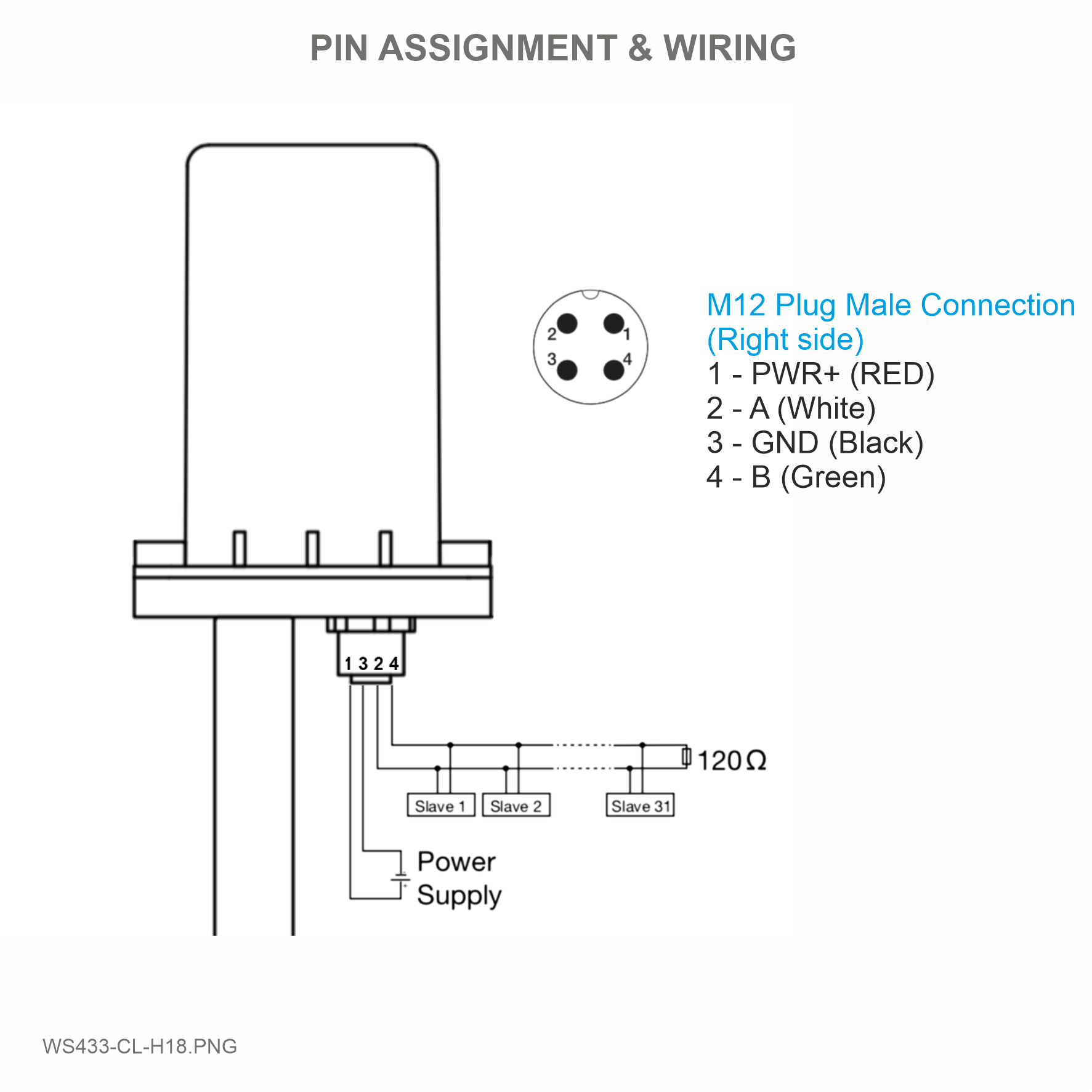
Memmap resgisters
You can download Modbus Memmap of WS433-CL with the following link:
https://filerun.daviteq.com/wl/?id=BKEaUzdArkoc0Hc7nfpRShdPVToVrqQZ
5.1.2 Add sensor node into WS433-CL-04 (1) through intermediate WS433-CL-04 (2) and Modbus
In case the sensor need to be added to WS433-CL-04 (1) has been installed in a high position, the sensor cannot be brought close to WS433-CL-04 (1). For more details:
5.2 Button Function
- Press and hold the button for 2 seconds => LED blinks once => Release the button to set Data rate RF 50kbps.
- Press and hold the button for 5 seconds => LED blinks twice => Release the button to set Data rate RF 625bps.
- Press and hold the button for 10 seconds => LED blinks 3 times => Release the button to reset RF parameters (frequency, RF output power, data rate), if held for more than 30 seconds then the button function does not work.
Reset default WS433:
- Frequency: 433.92 MHz
- RF transmit power: 15 dBm
- RF data rate: 50 kbps
5.3 Configuration
5.3.1 Sensor configuration
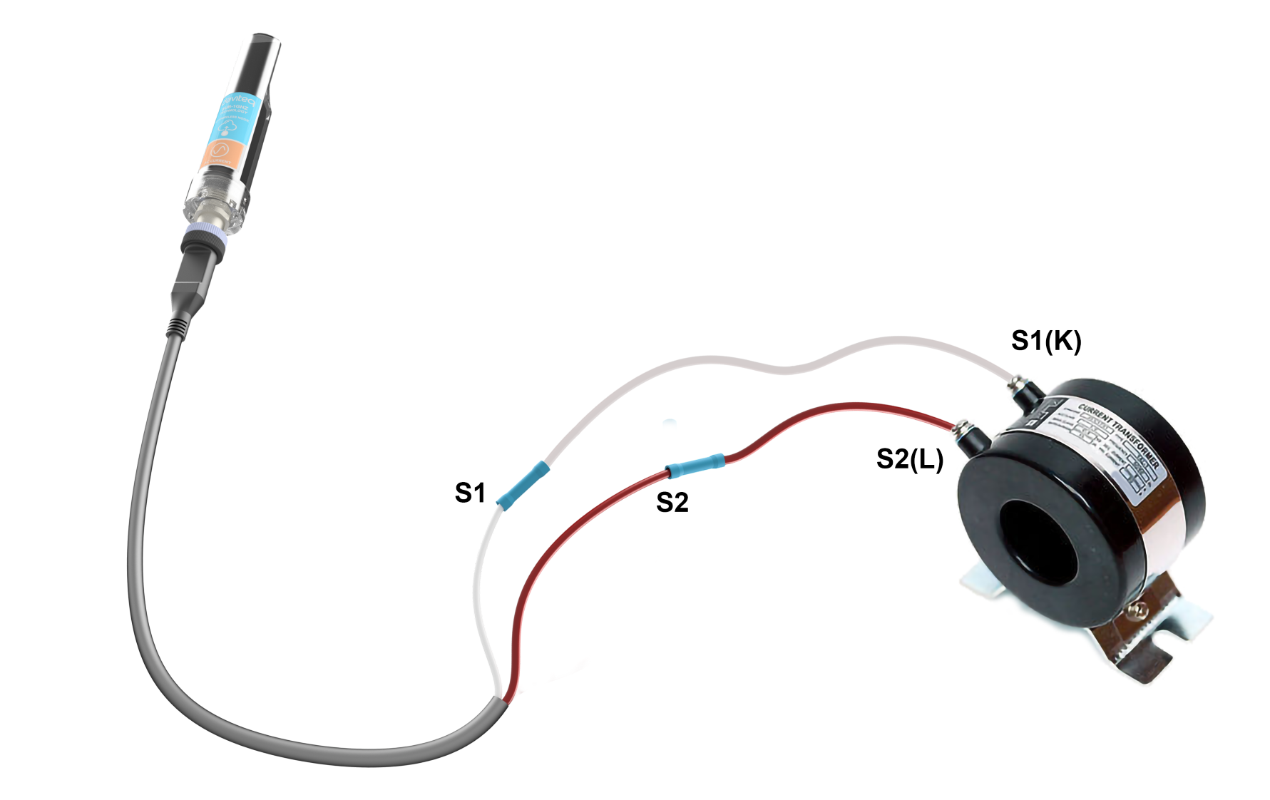
The WS433-AC wireless sensor measures AC current via CT (Current Transformer).
We need to check what the ratio on the CT is printed on the sticker. For example: 50/5A = 10, 75/5A=15, 100/5A = 20, ...
First, you need to prepare

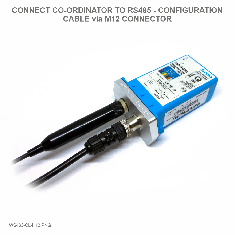
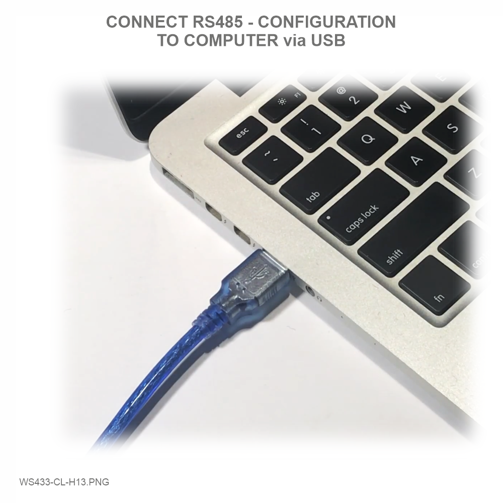
Then, use the RS485 configuration cable to communicate with the Co-ordinator WS433-CL-04 via Modbus software (in the link below), then write the the ratio of the CT into "Co-ordinator id" and sync with the sensor node.
Daviteq Modbus Configuration Tool: https://filerun.daviteq.com/wl/?id=qK0PGNbY1g1fuxTqbFW9SXtEvCw7bpc6
Template WS433-AC: https://filerun.daviteq.com/wl/?id=Nv5NoJleTianjd5LBNlWpDdMqKOIhOMq
How to use the Modbus configuration software
 |
 |
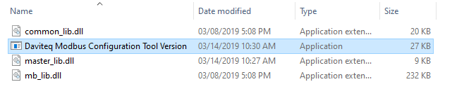
- Unzip file and run file application Daviteq Modbus Configuration Tool Version
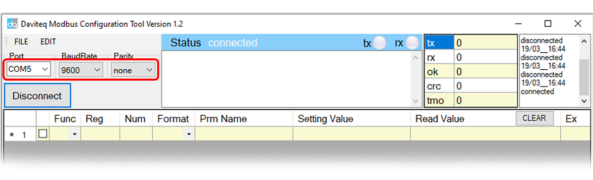
- Choose COM Port (the Port which is USB cable plugged in)
- Set the BaudRate: 9600, Parity: none

- Click “ Connect “ untill the Status displays “disconnected” to “connected“. It means the WS433-CL-04 is being connected with computer.
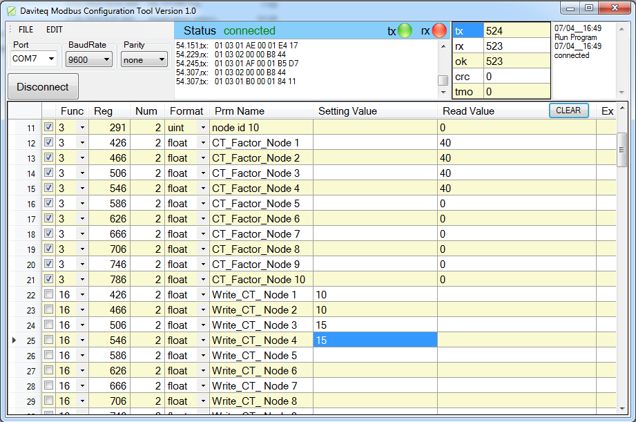
- Next, we need to import the configuration file for WS433-CL-04 by importing the csv file: Go to MENU: FILE / Import New / => select the file with name Template for WS433-AC.csv (after unzip the file).

- In the row Write_CT_Node , we write the the ratio of the CT of sensor node to co-ordinator id WS433-CL-04 by write the the ratio of the CT in column Setting Value then check the box Func to write the value => the value in the Read Value column show OK, that means the configuration is complete.
.png)
- You can now connect the Co-ordinator WS433-CL-04 using an RS485 connection to read data from the wireless sensor.
5.3.2 IO Wiring
On WS433-AC there are 2 wires marked S1 and S2, we connect the sensor to the current transformer according to S1 with S1 (K) and S2 with S2 (L) as shown below.
6. Installation
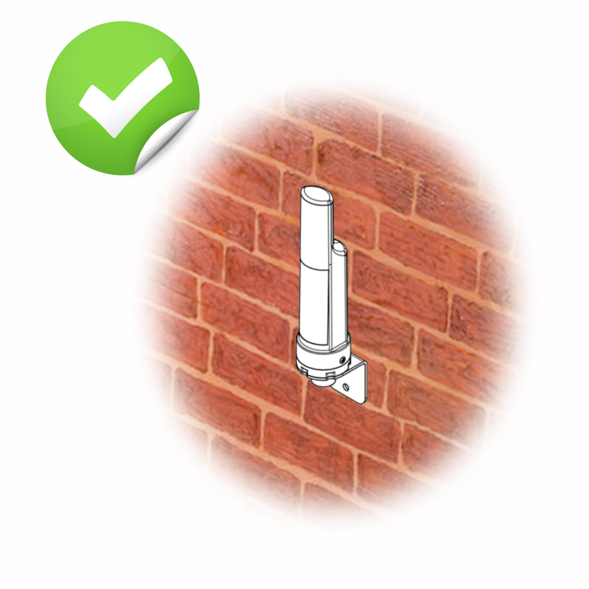
6.1 Installation location
The bracket will be fixed on the wall or material with a flat surface with double-sided 3M tape (included in the accessory bag in a carton box) or 2 x M4 screws (supplied by the customer);
When using 3M double sided tape, please install the sensor at a height of 2 meters or less.
ATTENTION:
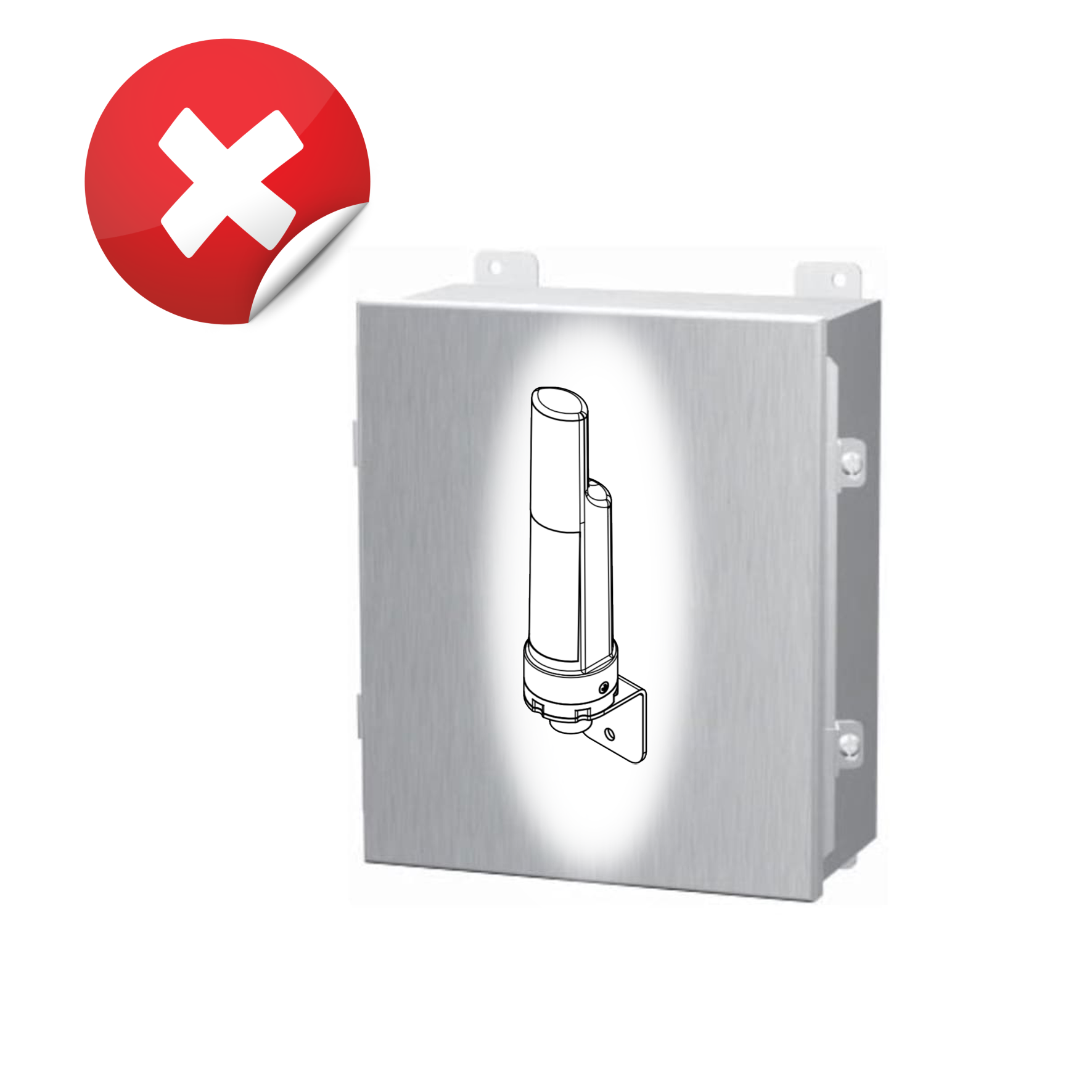
DO NOT install the Wireless sensor or its antenna inside a completed metallic box or housing, because the RF signal can not pass through the metallic wall. The housing is made from Non-metallic materials like plastic, glass, wood, leather, concrete, cement…is acceptable.
 |
 |
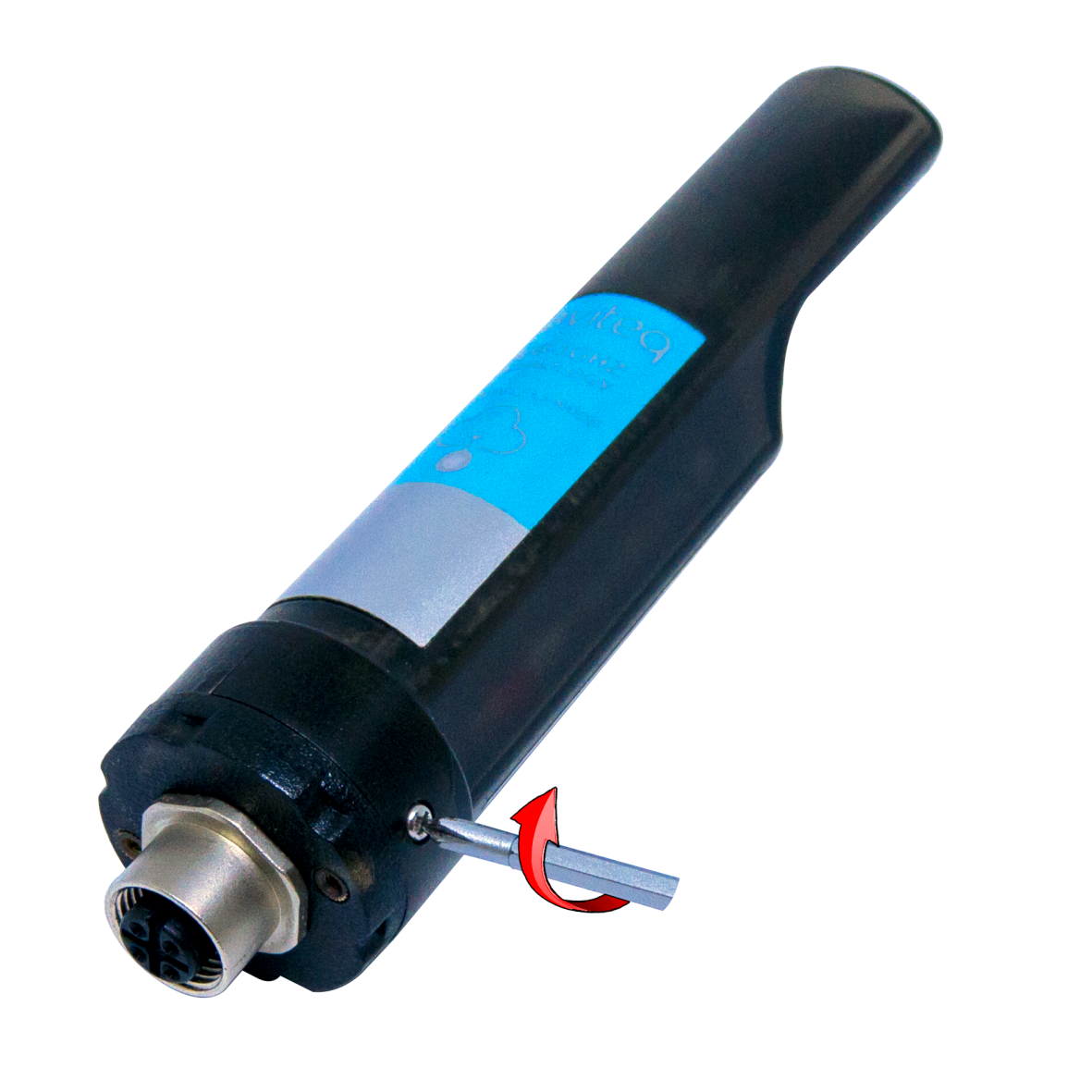
6.2 Power Supply & Battery installation
Steps for battery installation:
- Using Philips screw driver to unscrew M2 screw at the side of housing

- Carefully pull out the top plastic housing in the vertical direction
NOTE: Because of O-ring, it requires to have much pulling force at the beginning, therefore please do it carefully to avoid the damage of circuit board which is very thin (1.00mm);

- Insert the AA battery
Please take note the poles of battery
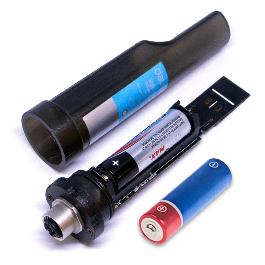
- Insert the top plastic housing and locking by M2 screw
7. Troubleshooting
| No. | Phenomena | Reason | Solutions |
| 1 | The status LED of wireless sensor doesn't light up |
|
|
| 2 | Wireless sensor not connected to co-ordinator |
|
|
8. Support contacts
|
Manufacturer
Daviteq Technologies Inc Email: info@daviteq.com | www.daviteq.com
|
Distributor in Australia and New Zealand
Templogger Pty Ltd Tel: 1800 LOGGER Email: contact@templogger.net |

No Comments