Daviteq Sigfox Sensor on SDR Dongle Gateway
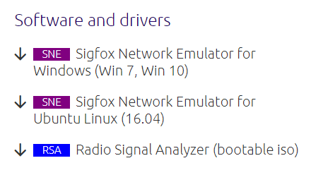
1. Download the Sigfox Network Emulator.
You can download SNE for the software and drivers from the link: https://support.sigfox.com/products#sdr
2. Register the device on the Sigfox Network Emulator of your local webpage.
Click CONFIGURATION > RADIO.
From the left side of the local web page, select RADIO for your Radio Configuration.
For example, choose RC4 from the Radio Configuration's dropdown menu if you want to connect to the device in RC4. 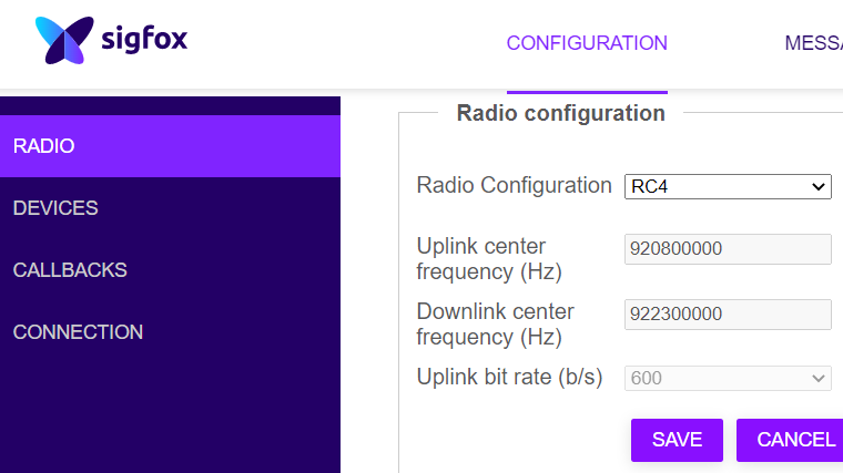
After completing your registration page, please click SAVE.
Next, click DEVICES.
Note: You can find the value for Identifier (hex!) which is the ID located on the label of the sensor.
For example, Device 1 has the digits of ID as 02A30DAD.
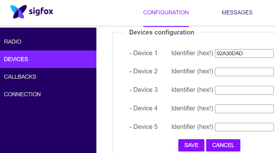
After completing your registration page, please click SAVE.
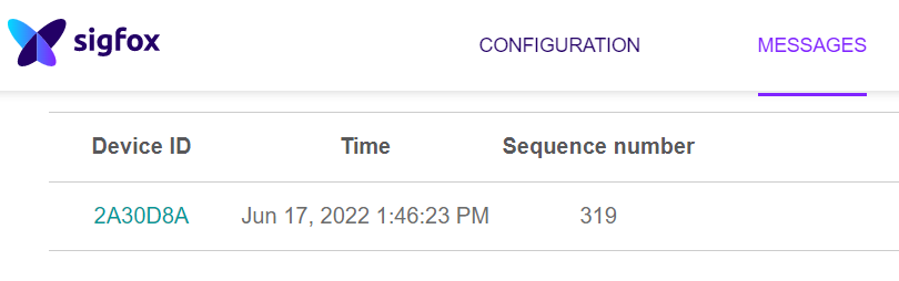
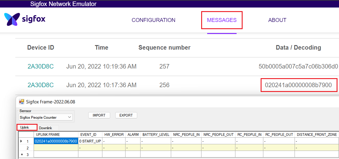
3. Manage your view for the payload of the device.
Click MESSAGES.
- The device has 2 modes of operation which are Configuration mode and Power mode. In order to be able to send data during the power supply provided, the power source should last after 60 seconds to enter the power mode.
-
Configuration mode allows you to read or write the parameter's value which is the property of R/W of your device such as CURRENT_CONFIGURATION, RADIO_CONFIG, SERVER_CONFIG, etc.
-
Power mode allows your device to transmit uplink or receive downlink data. This is when the sensor is ready to communicate with the Sigfox network.
- If your device operates with a period of time to send data, the device will send uplink data in every cycle.
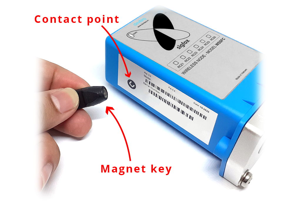
- If your device sends the uplink data intentionally, you can draw the Magnet key to the Contact point as below.
The device provides means to force an uplink transmission in one time.
In both cases, the data packet will be sent to your SDR Dongle gateway. Measuring data is formed in several specific payloads.
For the meaning of every uplink message or downlink data, please refer to the next section in the hint below:
Use of the Daviteq SigfoxFrame software
4. Send Downlink to the device
As your device communicates with the SDR Dongle, you can prepare downlink data in advance to meet the schedule right after one of the uplink frame transmissions from the device on the Sigfox network.
The downlink data is added to the device downlink queue, downlinks may be sent only after an uplink from the device.
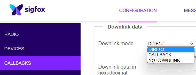
1. Click CONFIGURATION > CALLBACKS, select DIRECT in Downlink mode field
- If you plan to create the downlink data for your device, please follow the instruction below.
| Parameter | PRM_ADDRESS | PRM_LENGTH | PRM_FORMAT | PRM_VALUE | DOWNLINK_TYPE | Full Downlink |
| (bytes) | 1 | 1 | 4 | 2 | 8 | |
| DISTANCE_THRESHOLD | 0x32 | 0x02 | unit16 |
Example: 10 ==> 0x000A0000 |
0x0005 |
For the Sigfox People Counter sensor, a parameter "DISTANCE_THRESHOLD" that supports the downlink property should only calculate the value according to that PRM_VALUE format. The Example of a Decimal number "10" and a Hex number "000A0000" are shown, Full Downlink = 3202000A00000005. This indicates the value of the DISTANCE_THRESHOLD parameter is set to 10 if you write this downlink data into the device.
For example, your newly-calculated DISTANCE_THRESHOLD's value is 1600, Full Downlink = 3202064000000005.
For ease of calculation, you should identify a Decimal number, then convert it to a Hex number.
2. Enter your desired downlink data, 3202064000000005.
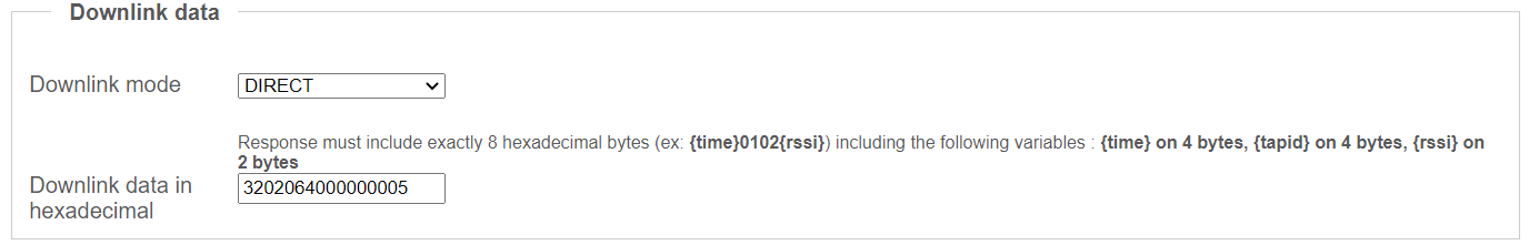
After completing your setting, please click SAVE.
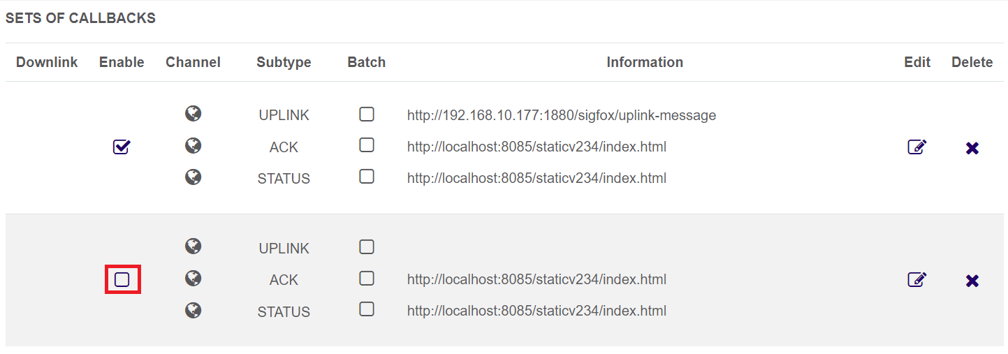
3. Enable your SET OF CALLBACKS.
5. Configure Callbacks to forward payloads to Microsoft Teams
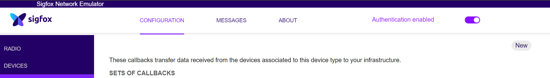
1. Click CONFIGURATION > CALLBACKS > New.
3. Select Type > UPLINK.
4. Select Channel > URL.
5. Select Use HTTP Method > POST.
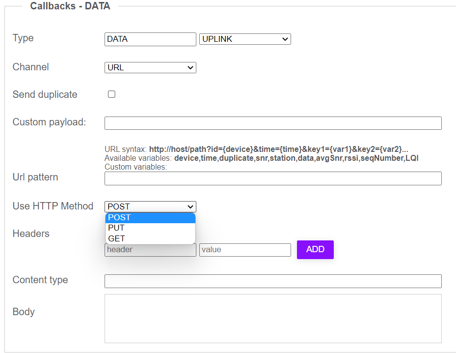
6. Fill out the form according to the following table:
| Field | Input field |
| URL pattern | http://192.168.10.177:1880/sigfox/uplink-message |
| Header |
Authorization |
| value |
BasicYXBwLWtleS05MWE2Y2FjMi03YzFhLTQ2Y2UtYWJhNS1jNWJjNmU2N2UwMmI6c2VjcmV0LWtleS1iZGIwNGYyOC1hYjcxLTQ1MDktOTE4Yi05NmJkMTMzZGMxNDA= |
|
Content type |
application/json |
|
Body |
{ "device": "{device}", "time": "{time}", "seqNumber": "{seqNumber}", "device": "{device}", "station": "{station}", "rssi": "{rssi}", "snr": "{snr}", "data": "{data}" } |
6. Configure Callbacks to forward payload to Daviteq Globiots platform
1. Click CONFIGURATION > CALLBACKS > New.
2. At the section Downlink data, select CALLBACK at Downlink mode field
4. Select Type > BIDIR
4. Select Channel > URL.
5. Select Use HTTP Method > POST.
6. Fill out the form according to the following table:
| Field | Input field |
| URL pattern | https://resources.globiots.com/rest/api/v1/sigfox-service/process-messages |
| Header |
Authorization |
| value |
Copy this value from Globiots: Login Globiots, click the Sigfox sensor name, click tab Sigfox Network Server Config, copy Header value and paste to value field on Callbacks-DATA section |
|
Content type |
application/json |
|
Body |
{ "device": "{device}", "time": "{time}", "seqNumber": "{seqNumber}", "device": "{device}", "station": "{station}", "rssi": "{rssi}", "snr": "{snr}", "data": "{data}" } |
No Comments