USER GUIDE FOR SIGFOX LIDAR PEOPLE COUNTER WSSFC-LPC
THIS IS OBSOLETE MANUAL
Please access https://www.iot.daviteq.com/wireless-sensors for updated manual
| WSSFC-LPC-MN-EN-01 |
AUG-2021 |
This document is applied for the following products
| SKU | WSSFC-LPC | HW Ver. | 1.1 | FW Ver. |
1.0
|
| Item Code |
WSSFC-LPC-9-01 |
SIGFOX LIDAR PEOPLE COUNTER, INTERNAL ANTENNA, TYPE AA BATTERY 1.5VDC, IP5X, RC2-RC3-RC4-RC5 ZONES |
|||
| WSSFC-LPC-8-01 |
SIGFOX LIDAR PEOPLE COUNTER, INTERNAL ANTENNA, TYPE AA BATTERY 1.5VDC, IP5X, RC1-RC6-RC7 ZONES |
||||
0. Configuration Check List

|
STEP 1: Select RC |
|
|
1. Select RC zone |
RC zones selection 1, 2, 4,... is RCZ1, RCZ2, RCZ4,... (refer to section 6)
|
|
STEP 2: Check ID and PAC |
|
|
Use Modbus Configuration Cable to read the ID and PAC values |
Refer to register address 8 and 10 (DEC) |
|
STEP 3: Configure the sensor's operating parameters |
|
| Configure parameters like cycle send data, alarm, a, b,... | Refer to the configuration section 5 and section 6 |
|
STEP 4: Add device to Backend Sigfox |
|
| refer to section 5.2 for details | |
|
STEP 5: Installation |
|
| refer to section 7 for details |
1. Functions Change Log
| HW Ver. | FW Ver. | Release Date | Functions Change |
| 1.1 | 1.0 | DEC-2020 |
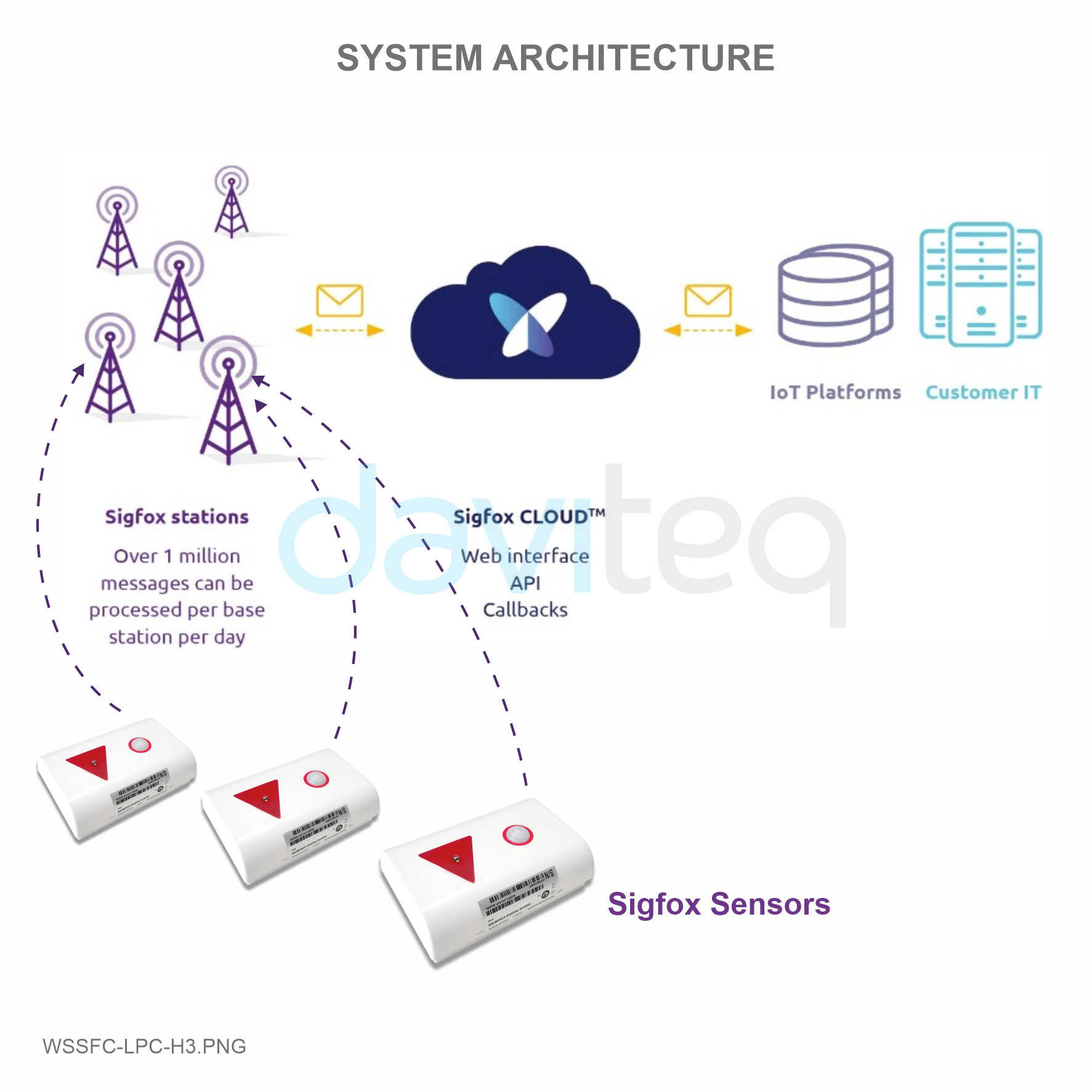
2. Introduction
WSSFC-LPC is a Sigfox sensor with built-in advanced Lidar sensor to detect and ranging people. It can count the people walk thru with accuracy higher than 90%. The sensor is not affected by temperature, humidity, RF noise and less affected by ambient light... With Ultra-low power design and smart firmware allow the complete Wireless and Sensor package run on AA battery 1.5V in many years. Moreover, it can be powered by external power supply at the same time. It can support all regions of Sigfox network in over the World, RC1, RC2, RC3, RC4, RC5, RC6, RC7.
Typical Applications: People counter for public toilet, People counter for Store, shop...

3. Specification
| SENSOR SPECIFICATION | |
| Sensor technology | Lidar |
| Detection range | max 4m |
| Detection cone | 27 degree |
| Working temperature | -40 .. + 60 oC |
| Working humidity | 0 .. 100% RH, non-condensing |
| SIGFOX SPECIFICATION | |
| Sigfox zones | select RC2-RC3-RC4-RC5 or RC1-RC6-RC7 |
| Functions | Sending data in interval or when alarms occur |
| Antenna | Internal Antenna 2 dbi |
| Configuration | via offline USB cable (PC software is supplied at free) |
| Battery | Battery AA Type 1.5VDC and 7..48VDC (AC adapter not included |
| RF Module complies to | CE, FCC, ARIB |
| Working temperature | -40°C..+60oC (using Energizer Lithium Ultimate AA battery) |
| Dimensions | H120xW80xD45 |
| Net-weight | ≺150 grams |
| Housing | Self-extinguisher ABS, Dust and vapor protection |
| Mounting | Ceiling mount |
4. Dimensions

5. Operation Principle
Upon power on, the Sigfox node has 60 seconds to wait for off-line configuration (via cable with ModbusRTU protocol)
After 1 minute 30 seconds later the device will send the first data packet and at the same time wait for the downlink packet from the Base Station.
Then during the operation, there are 03 cases of sending data to base station:
1. When the sensor sampling time interval is reached, the Sigfox node will read the data from Input or sensor and performing the calculation. After that it will check calculated value with alarm thresholds. If the calculated was out off the threshold values (Lo or Hi), called alarm, and the number of times of alarm did not pass the limit of number of alarms, then it will send data to Base station immediately;
NOTE:
Once sending the data to base station by this alarm event, the timer of sending time interval will be reset;
2. When the sending time interval is reached, it will send data to Base station immediately, regardless of value;
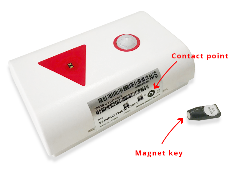
3. By using the magnet key, the Sigfox node can be triggered to send data to base station immediately. There will be a beep sound from the buzzer meaning the data has been sent. (Buzzer will be updated in the latest version)

NOTE:
Once sending the data to base station by the magnet key, the timer of sending time interval will be reset;
The shortest time interval between the two manual triggers is 15s. if shorter than 15s, there will be no data sending.
5.1 RC technical details
The RF transmit power will be automatically set as the max value as allowed by the Zone.
Sigfox Radio Configuration (RC) defines the radio parameters in which the device shall operate: Sigfox operating frequencies, output power, spectrum access mechanism, throughput, coexistence with other radio technologies, etc.
Each radio configuration includes 4 uplink classes: 0u, 1u, 2u, and 3u.
The Sigfox network globally works within the ranges from 862 to 928 MHz. But not all RCs require such a wide range of operation.
| RC1 | RC2 | RC3 | RC4 | RC5 | RC6 | RC7 | |
|---|---|---|---|---|---|---|---|
| Uplink center frequency (MHz) | 868.130 | 902.200 | 923.200 | 920.800 | 923.300 | 865.200 | 868.800 |
| Downlink center frequency (MHz) | 869.525 | 905.200 | 922.200 | 922.300 | 922.300 | 866.300 | 869.100 |
| Uplink data rate (bit/s) | 100 | 600 | 100 | 600 | 100 | 100 | 100 |
| Downlink data rate (bit/s) | 600 | 600 | 600 | 600 | 600 | 600 | 600 |
| Sigfox recommended EIRP (dBm) | 16 | 24 | 16 | 24 | 14 | 16 | 16 |
| Specifics | Duty cycle 1% * | Frequency hopping ** | Listen Before Talk *** | Frequency hopping ** | Listen Before Talk *** | Duty cycle 1% * |
* Duty cycle is 1% of the time per hour (36 seconds). For an 8 to 12 bytes payload, this means 6 messages per hour, 140 per day.
** Frequency hopping: The device broadcasts each message 3 times on 3 different frequencies. Maximum On time 400 ms per channel. No new emission before 20 s.
*** Listen Before Talk: Devices must verify that the Sigfox-operated 200 kHz channel is free of any signal stronger than −80 dBm before transmitting.
Sigfox’s high limit EIRP recommendation is included in each column although regulations sometimes allow for more radiated power than the Sigfox recommendation.
Sigfox’s recommendation is set to comply with the Sigfox technological approach of:
- Low current consumption
- Balanced link budget between uplink and downlink communication
5.2 Add a device to the Backend Sigfox
Step 1: Log in to the sigfox backend website

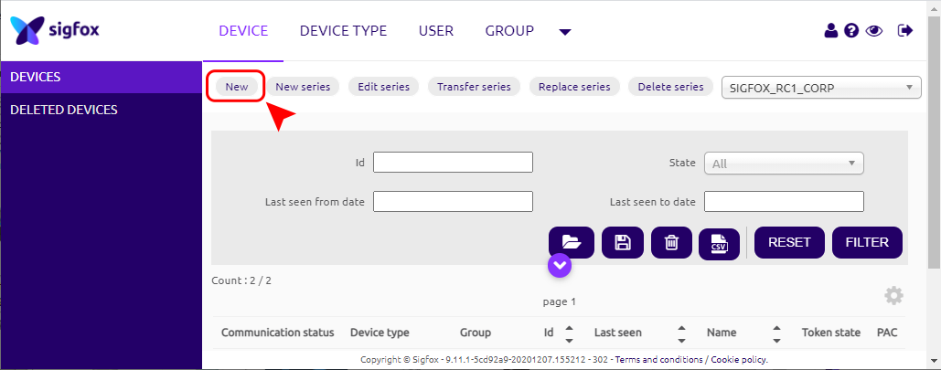
Step 2: Click on Device

Step 3: Click New → Select a group
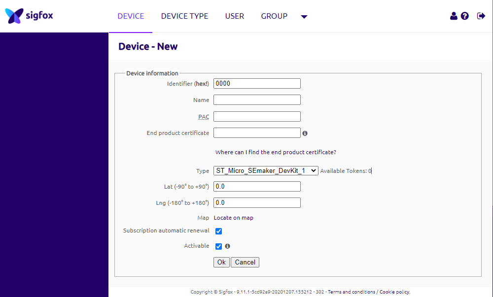
Step 4: Fill in the required information
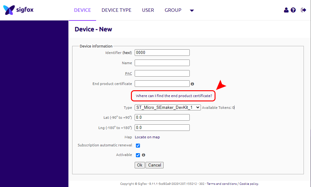
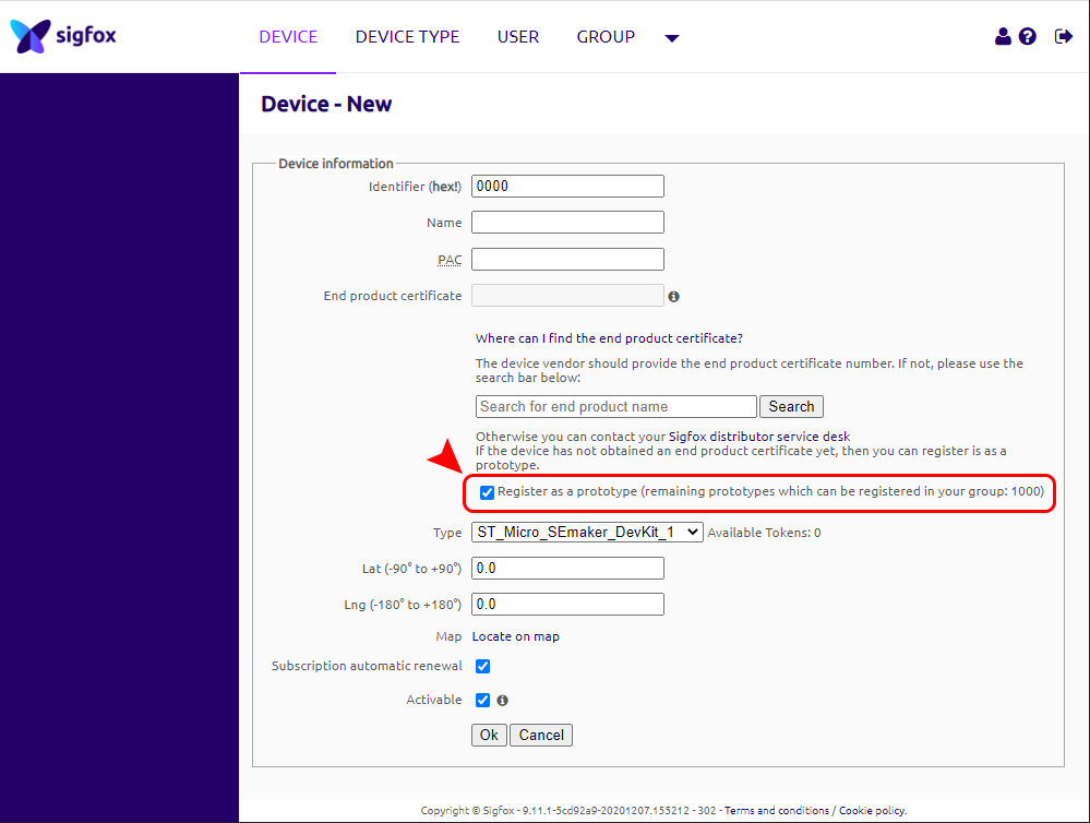
Note: Some of our products may not have end product certification in time, to add the product to Backend Sigfox please follow the steps below.
Click on the text as shown below
Check the box as shown below to register as a prototype
5.3 Measurement principle of Sigfox People Counter
5.3.1 Overview
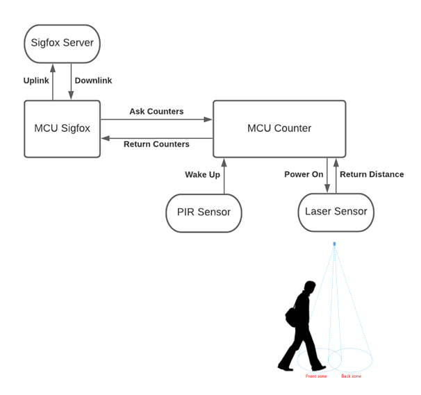
5.3.1.1 MCU Counter counts people in and out
Normally MCU Counter will be in sleep state, PIR Sensor works with low current, Laser Sensor is in power off state.
When someone approaches, PIR Sensor will wake up MCU Counter → MCU Counter power on Laser Sensor →
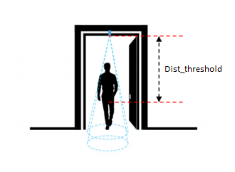
Laser Sensor returns the measured distance value from the Laser Sensor (mounted on the ceiling) to the nearest obstacle down to the floor.
Dist_threshold mechanism:
- The sensor will measure the distance from the sensor (on the ceiling) to the floor, when there is an obstacle, the person is under the sensor, the sensor will measure the distance from the sensor to the obstacle, that person => will get the DistX value
- When DistX < Dist_threshold, the sensor detects that someone is standing below
- When DistX > Dist_threshold + dist_hys, the sensor confirms that no one is under
MCU Counter performs counting people in and out based on the principle of counting people in below.
When there are no people nearby, the MCU Counter will power off the Laser Sensor, and the MCU Counter will also sleep.
5.3.1.2 MCU Sigfox
Normally the Sigfox MCU sleeps.
When it comes to the sampling_rate cycle, the Sigfox MCU wakes up reading the Counters values from the MCU Counter. Read-in values include NRC_People_in, NRC_People_out, Dist_front_zone, Dist_back_zone.
The Sigfox MCU will calculate the RC_People_in, RC_People_out based on saving the last NRC_People_in, NRC_People_out values before sending to the Sigfox Server. RC_People_in = NRC_People_in (recently read) - NRC_People_in (saved). NRC_People_out = NRC_People_out (recently read) - NRC_People_out (saved).
If (RC_People_in > count_threshold) or (RC_People_out > count_threshold) then the Sigfox MCU will send the Uplink to the Sigfox Server. Then will delete RC_People_in and RC_People_out to 0. MCU Sigfox will save the last NRC_People_in, NRC_People_out values before sending to Sigfox Server.
When the cycle_send_data is reached, the Sigfox MCU wakes up reading the Counters values from the MCU Counter, calculates the new RC_People_in, RC_People_out and sends the Uplink to the Sigfox Server. Then will delete RC_People_in and RC_People_out to 0. MCU Sigfox will save the last NRC_People_in, NRC_People_out values before sending to Sigfox Server.
5.3.2 The principle of counting people
5.3.2.1 Overview
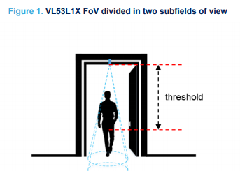
Counting people with the VL53L1X consists of using the multiple zones of the sensor receiving SPAD area, and of configuring it with two distinct fields of view (FoV), to alternatively get a ranging distance from them and consequently recognize the movements of a person. Using this method, the number of people occupying a meeting room, accessible from a reasonably narrow access, is known at all times by detecting the entrances and exits of the attendees.
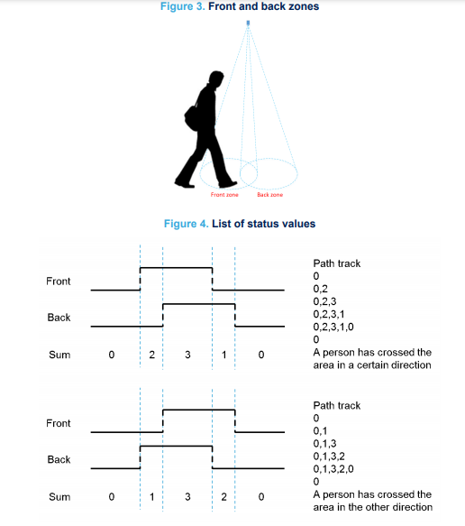
By measuring and analyzing the distances of targets within the FoVs of a front and back zone (see figure below and Figure 3. Front and back zones), a simple algorithm can detect the direction a person crosses the area under the two FoVs. This algorithm "understands" that someone is under one of the FoV as long as the distance measured by the sensor under this FoV is between 0 and a threshold value specified in mm.
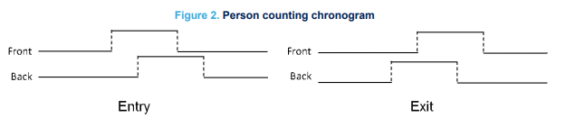
From a timing perspective, the sensor alternatively ranges on each of the two zones, for a very short period of time in milliseconds. It is possible to determine in which direction a person crosses the area, depending in which order this person has been detected in the two zones, as shown in the figure below.
5.3.2.2 Algorithm description
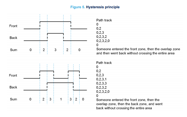
The counting algorithm example relies on a list of states that have to occur in a certain order to detect if a person has crossed the specified area and in which direction this area has been crossed. These states are stored in a list and compared to two default lists of states that represent how the area is crossed in two different directions. When no-one is seen in either of the two zones, the list of states is reset.
If we consider that a person detected in the front zone equals 2, and a person detected in the back zone equals 1, the algorithm adds the value of the two states and stores the result as soon as it changes.
Eventually, if the consecutive states in the list are 0, 1, 3, 2, 0 or 0, 2, 3, 1, 0 this means a person has been detected in one direction or the other, as described in Figure 4. List of status values.
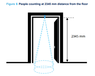
5.3.2.3 Hysteresis
The algorithm validates a crossing event only when a person has fully crossed the two zones. It does not validate the event when the person remains for a long time under the FoV or when the person decides to return from the place he came from.
This is illustrated in the figure below: the algorithm stops and the list of states is reset as soon as no-one is detected in any of the two FoVs.
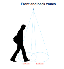
5.3.2.4 Ranging on the floor to determine the threshold
Reliability of the algorithm relies on the accuracy of the setup which detects the distance between the sensor and the floor. This can be ensured only if nothing (e.g. no obstacle or static object) blocks the front and back FoVs. To assess if a setup is reliable, a significant number of distances can be measured with the sensor. Then, a histogram diagram can be established to confirm that the sensor is correctly set up and that no target is within its FoVs.
A threshold needs to be defined, which is achieved after having ranged on the flooring material over a significant number of samples. In fact, the threshold should be chosen so that all the measured distances (when ranging the floor) are greater than this threshold. We recommend that at installation of the application, an autocalibration routine is launched to calculate the threshold. This is because flooring material can be different in many locations.
Figure 6. People counting at 2345 mm distance from the floor. The distance between the sensor and the floor is 2345 mm, and as the minimum distance measured by the sensor is 2290 mm, the threshold is thus less than 2290 mm.
Note: This calibration should be performed in the worst ambient light conditions, to maximize the jitter and obtain a threshold that is relevant to all possible ambient lighting conditions the counting setup is exposed to.
5.4 Payload Data
The folllowing is the format of payload data will be sent to Sigfox server.
5.4.1 Payload for uplink 12 bytes
|
Sensor type (1 byte) |
Status (1 byte) |
NRC_People_in (2 bytes) |
NRC_People_out (2 bytes) |
RC_People_in (1 byte) |
RC_People_out (1 byte) |
Dist_front_zone (2 bytes) |
Dist_back_zone (2 bytes) |
|
Data |
Size (byte) |
Bit |
Format |
Meaning |
|
Sensor type = 0x13 |
1 |
all |
Uint8 |
Sensor type = 0x13 means Sigfox People Counter |
|
Status: battery level |
1 |
Bit 7 and 6 |
Uint8 |
Battery capacity in 04 levels 11: battery level 4 (99%) 10: battery level 3 (60%) 01: battery level 2 (30%) 00: battery level 1 (10%) |
|
Status: error |
|
Bit 5 and 4 |
|
Node status 01: hardware sensor error 00: no error |
|
NRC_People_in |
2 |
all |
Uint16 |
Non-resettable counter |
|
NRC_People_out |
2 |
all |
Uint16 |
Non-resettable counter |
|
RC_People_in |
1 |
all |
Uint8 |
Reset to 0 after sending to Sigfox server |
|
RC_People_out |
1 |
all |
Uint8 |
Reset to 0 after sending to Sigfox server |
|
Dist_front_zone |
2 |
all |
Uint16 |
Distance of front zone |
|
Dist_back_zone |
2 |
all |
Uint16 |
Distance of back zone |
5.4.2 Payload for Downlink, length is 8 bytes
The Sigfox node is only able to receive max 04 downlinks a day, each downlink will be waiting in every 06 hours.
User can set the down link data in Sigfox back-end system in advance, whenever the Sigfox node connected to base stations and with downlink waiting is enable at that time (one time in 6 hours), the downlink data will be loaded to Sigfox node.
The downlink data can be any configuration parameter.
Please pay attention when send downlink data. If there was a mistake in sending wrong data, it would cause the Sigfox node not working properly and user need to configure it by offline cable!!!
Downlink payload format:
|
Prm_adr (1 byte) |
Prm_len (1 byte) |
Prm_value (6 bytes) |
|
Prm_name |
Prm_adr |
Prm_len |
Comment |
|
cycle_send_data |
0x12 |
0x04 |
|
|
Count_threshold |
0x44 |
0x02 |
|
|
Dist_threshold |
0x46 |
0x02 |
|
Examples of Downlink data to configure the Sigfox node
Example 1: Write down cycle_send_data = 30 minutes
Convert minutes to seconds: 30 minutes = 30 *60 = 1800 seconds
Convert 1800 from DEC to HEX => 0x00000708 (4 bytes)
=> Downlink will be 1204000007080000, where is:
| Prm_adr | Prm_len | Prm_value | (remainder doesn't matter) |
| 12 | 04 | 00000708 | 0000 |
Example 2: Write down Count_threshold = 10
Convert 10 from DEC to HEX to 0x000A (2 bytes)
=> Downlink will be 4402000A00000000, where is:
| Prm_adr | Prm_len | Prm_value | (remainder doesn't matter) |
| 44 | 02 | 000A | 00000000 |
6. Offline configuration
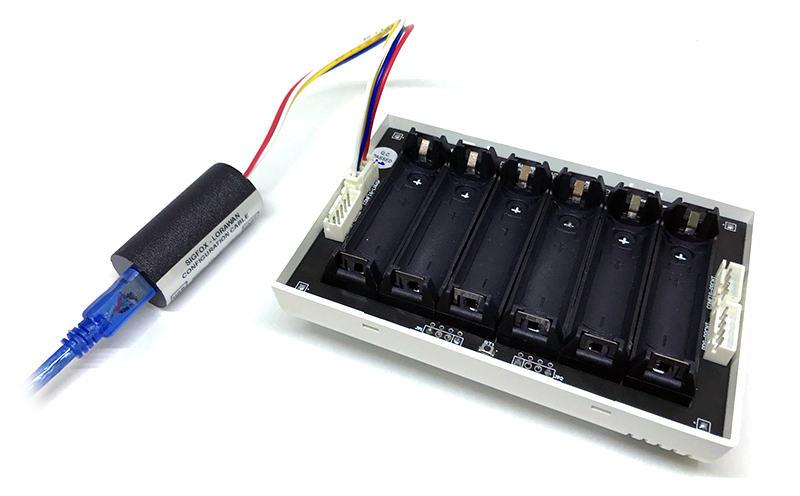
Using the configuration cable to connect to the sensor as below picture.

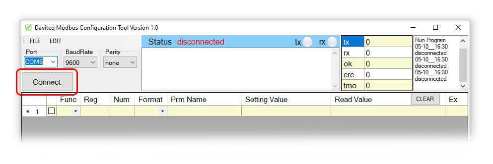
Serial port configuration on computer: 9600 baud, None parity, 1 stop bit.
Reading data by Function 3.
Writing data by Function 16.
During connection with Modbus configuration tool, the Sigfox node will send all data in realtime: Battery, Battery level, Vref, Button status, reed switch status, PCB temperature, Measured value, alarm status.
Step to configure & check data:
NOTE:
The Modbus configuration can be done in the first 60s after power up the Sigfox node. After 60s, if user can not finish the configuration, user need to reset the power of Sigfox node again, by removing battery in at least 15s.
Step 1: Install the Modbus Configurator Software in the link below
https://filerun.daviteq.com/wl/?id=yDOjE5d6kqFlGNVVlMdFg19Aad6aw0Hs
How to use the Modbus configuration software
Step 2: Plug the configuration cable to Computer via USB port;

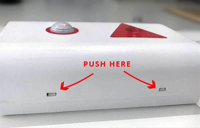
Step 3: Open the housing by using flat head screws to push into 2 reed joints;
Step 4: Plug the connector to the configuration port;
Step 5: Import the configuration file by importing the csv file: Go to MENU: FILE / Import New / => select the file with name CONFIGURATION TEMPLATE FILE FOR SIGFOX.csv (in the link below). Then click Connect;
CONFIGURATION TEMPLATE FILE FOR SIGFOX WSSFC-LPC.csv
6.1 Data table
| Modbus Register (Decimal) | Modbus Register (Hex) | Function Code | # of Registers | Description | Range | Default | Format | Property | Comment |
| 0 | 0 | 3 | 2 | device info | string | Read | Product name | ||
| 2 | 2 | 3 | 4 | firmware version | string | Read | |||
| 6 | 6 | 3 | 2 | hardware version | string | Read | |||
| 8 | 8 | 3 | 2 | device ID | hex | Read | Product ID | ||
| 10 | A | 3 | 4 | device PAC | hex | Read | Product PAC |
6.2 Configuration table
| Modbus Register (Decimal) | Modbus Register (Hex) |
Function Code (Read) |
Function Code (Write) |
# of Registers | Description | Range | Default | Format | Property | Comment |
| 270 | 10E | 3 | 16 | 1 | Radio Configuration | 1, 2, 4 | 4 | uint16 |
Read/ Write |
RC zones selection 1, 2 ,4 is RCZ1, RCZ2, RCZ4 |
| 271 | 10F | 3 | 16 | 1 | tx_power | 20 | int16 |
Read/ Write |
RF Tx power | |
| 272 | 110 | 3 | 16 | 1 | tx_repeat | 0-1 | 1 | uint16 |
Read/ Write |
Number of repeat, 0: 1 time, 1: 3 repeats |
| 273 | 111 | 3 | 16 | 1 | downlink_flag | 0-1 | 1 | uint16 |
Read/ Write |
1: enable Downlink, 0: disable Downlink |
| 274 | 112 | 3 | 16 | 2 | cycle_send_data | sec | 3600 | uint32 |
Read/ Write |
Data sending cycle, in seconds |
| 280 | 118 | 3 | 16 | 2 | sampling_rate | sec | 120 | uint32 |
Read/ Write |
Sensor/Input 1 sampling rate, in seconds |
| 324 | 144 | 3 | 16 | 1 | count_threshold | 20 | hex |
Read/ Write |
threshold count on how many people send sigfox | |
| 325 | 145 | 3 | 16 | 1 | distThreshold | 1600 | uint16 | Read / Write | Threshold setting for laser sensor to distinguish between when people are present and when no one is standing under the sensor The laser sensor will measure the distance value from the sensor (ceiling) to the floor.
|
|
| 326 | 146 | 3 | 16 | 1 | distHys | 100 | uint16 | Read / Write | Hys of distThreshold | |
| 327 | 147 | 3 | 16 | 1 | inter_meas_period | 48 | uint16 | Read / Write | The sampling time of the sensor laser |
7. Installation
7.1 Locate the good place for Radio signal
To maximize the distance of transmission, the ideal condition is Line-of-sight (LOS) between the Sigfox sensor and Base station. In real life, there may be no LOS condition. However, the Sigfox sensor still communicate with Base station, but the distance will be reduced significantly.
ATTENTION:
DO NOT install the Sigfox sensor or its antenna inside a completed metallic box or housing, because RF signal can not pass through metallic wall. The housing is made from Non-metallic materials like plastic, glass, wood, leather, concrete, cement…is acceptable.
7.2 Mounting
- Installation method: Mount to the ceiling
- Locate the mounting position at the entrance where people pass by, and out of direct sunlight
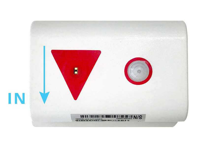
- The direction of the triangle is the direction of counting people entering as specified in the payload
- Determine the correct orientation to install the bottom cover to the ceiling in the correct direction
- WARNING:
- Avoid placing hands or heavy objects on the laser sensor surface or the PIR sensor surface, as this may cause damage to the device;
- Periodically use a clean cloth moistened with 70 degrees of alcohol to wipe the surface of the 2 sensors to keep the sensor clean and accurate.
Step 1: Determine the direction of people entering the room of the sensor
Step 2: Mount the bottom housing of the sensor to the ceiling by fasten the 2 screws to the ceiling located at the 2 diagonal corners of the bottom cover.
- Use the 2 screws that are included to be used to attach the sensor to surfaces such as: Wood, composite plastic.
- If the ceiling surface is made of plaster, it is recommended to use a special insert so that the device can firmly adhere to the ceiling surface. Avoid dropping the device.
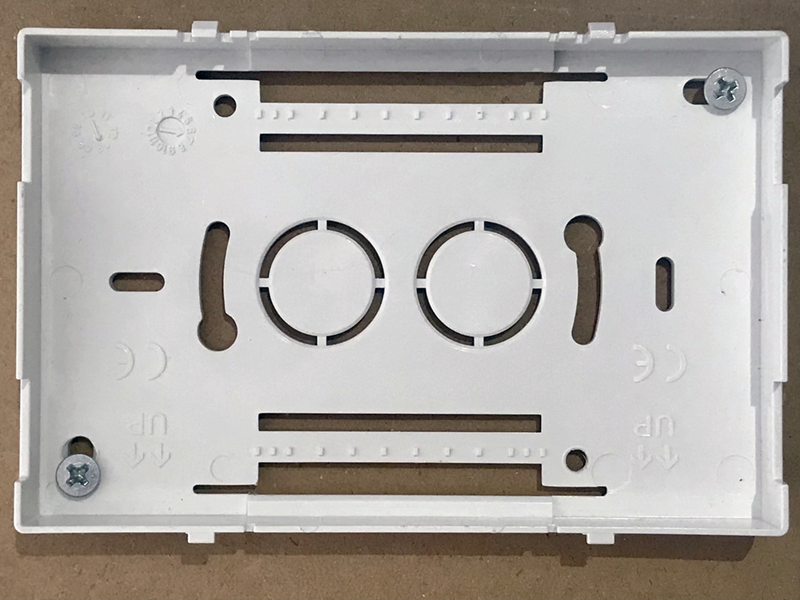
Step 3: Attach the top and bottom housings (note the 2 reed joint)
- Fit the main body to the bottom cover in the correct direction: the 2 reed joints on the bottom cover should fit into the main body on the side labeled with the device.
- Make sure that the main body is fully engaged with the bottom cover, then release the hand.
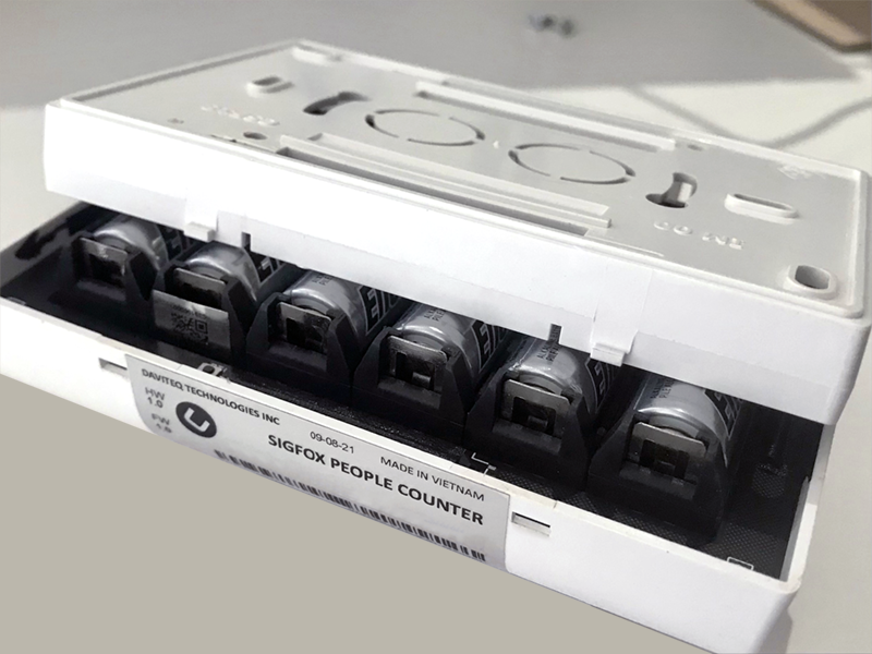
7.3 Battery installation

Steps for battery installation:
Step 1: Using flat head screws to push into 2 reed joints
Step 2: Open the housing, then insert 06 x AA 1.5VDC battery, please take note the poles of the battery
ATTENTION:
REVERSED POLARITY OF BATTERIES IN 10 SECONDS CAN DAMAGE THE SENSOR CIRCUIT!!!
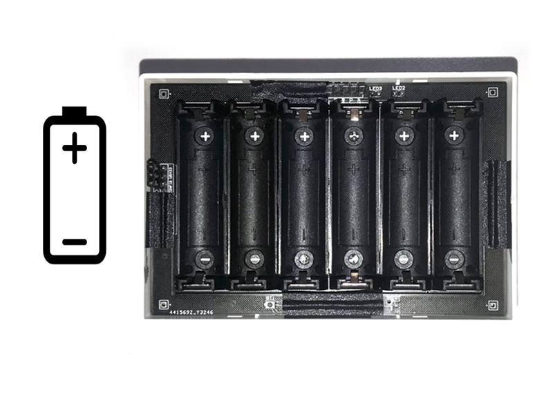
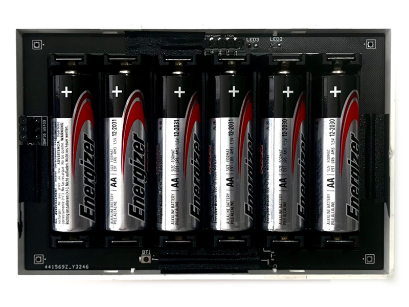
Step 3: Insert the top plastic housing (Please note the 2 reed joint)
8. Troubleshooting
| No. | Phenomena | Reason | Solutions |
| 1 | Node does not send RF to base station periodically, LED does not blink |
|
|
| 2 | Node does not send RF to base station according to the alarm, LED does not blink |
|
|
| 3 | Node does not send RF to base station when activated by the magnetic switch, LED does not blink |
|
|
| 4 | Node has blinked LED when sending RF but the base station cannot received |
|
|
| 5 | Node has sent RF but the LED does not blink |
|
|
| 6 | The measurement values from sensor do not change, keep constant values for long time |
|
|
| 7 | The node does not send RF and the RF module is hot |
|
|
| 8 | RSSI is weak and often loses data |
|
|
9. Support contacts
|
Manufacturer
Daviteq Technologies Inc Email: info@daviteq.com | www.daviteq.com
|
|
|
No Comments