USER GUIDE FOR SIGFOX SENSOR WITH ANALOG INPUT WSSFC-AI
THIS IS OBSOLETE MANUAL
Please access https://www.iot.daviteq.com/wireless-sensors for updated manual
| WSSFC-AI-MN-EN-01 |
FEB-2020 |
This document is applied for the following products
| SKU | WSSFC-AI | HW Ver. | 2.4 | FW Ver. | 1.9.3 |
| Item Code |
WSSFC-AI-9-01 | Sigfox Sensor with Analog input 0-20mA or 0-10VDC, pre-calibrated, Internal antenna, Type C battery 1.5 - 3.6VDC, IP67, M12-M for sensor connection, M12-F for external power supply, RC2-RC3-RC4-RC5 zones | |||
| WSSFC-AI-8-01 | Sigfox Sensor with Analog input 0-20mA or 0-10VDC, pre-calibrated, Internal antenna, Type C battery 1.5 - 3.6VDC, IP67, M12-M for sensor connection, M12-F for external power supply, RC1-RC6-RC7 zones | ||||
1. Functions Change Log
| HW Ver. | FW Ver. | Release Date | Functions Change |
| 1.0 | 1.0.1 | FEB-2020 | |
| 1.0 | 1.0.1 | 08-MAY-2020 | Updated correct file for CONFIGURATION TEMPLATE FILE FOR SIGFOX WSSFC-AI FW1.9.3.csv |
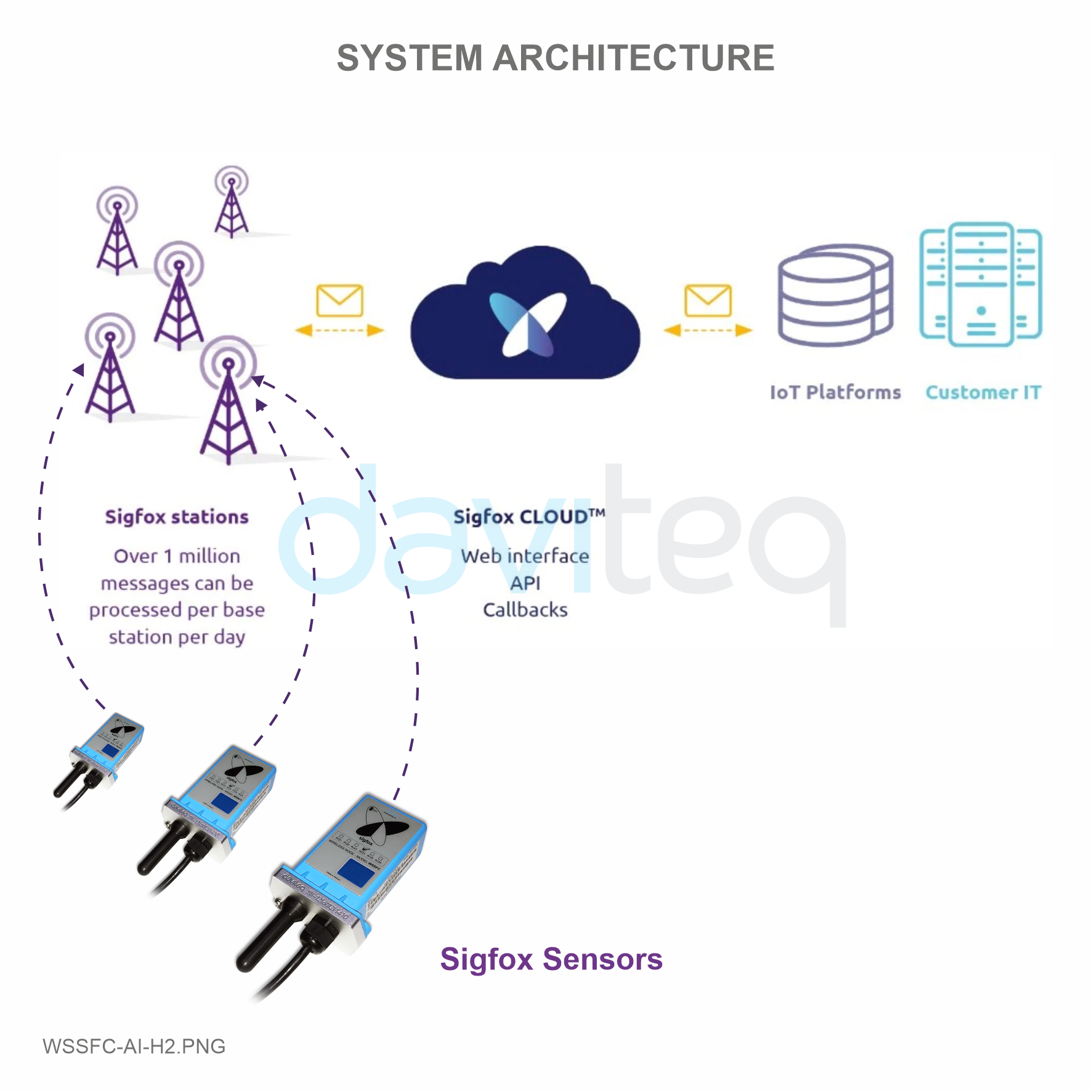
2. Introduction
WSSFC-AI is the modular design Sigfox wireless sensor, based on 10-year experience in design and manufacturing Industrial sensor of Daviteq Company. It can accepts the analog output signal 0-20mA/0-10VDC from any sensor, transmitter...It can supplies the power to external sensor at 15VDC @ 50mA max. With Ultra-low power design and smart firmware allow the complete Wireless and Sensor package run on a Single battery C type up to 10 years. WSSFC-AI can support all regions of Sigfox network in over the World, RC1, RC2, RC3, RC4, RC5, RC6, RC7.

3. Specification
| Input | 01 x Analog input, 0 .. 20mA or 0..10VDC, selectable |
| Accuracy | 0.05% of span |
| Resolution | 1/3000 |
| Temperature drift | < 50ppm |
| Power supply to sensor | 15VDC @ max 50mA |
| Electrical connection | M12-M connector |
| Sigfox zones | select RC2-RC3-RC4-RC5 or RC1-RC6-RC7 |
| Antenna | Fixed external Antenna 2.67 dbi |
| Battery | 01 x C Type 1.5 - 3.6VDC, working time up to 10 years (depends on configuration), extendable by external battery box or power supply |
| RF Module complies to | CE, FCC, ARIB |
| Working temperature | -40oC..+85oC (using LS26500 battery) |
| Dimensions | H106xW73xD42 (Wireless part only) |
| Netweight | 190 grams (Wireless part only) |
| Housing | Aluminum + Polycarbonate plastic, IP67 |
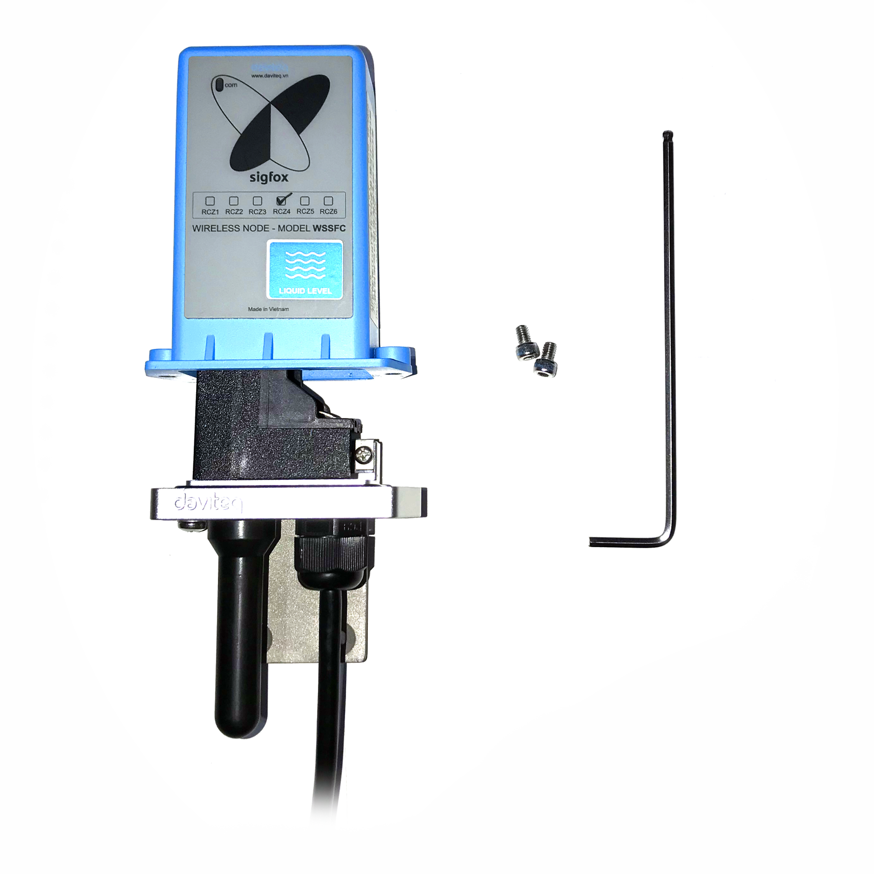
4. Product Pictures
|
 |
 |
 |
 |
 |
 |
 |
5. Operation Principle
Upon power on, the Sigfox node has 60 seconds to wait for off-line configuration (via cable with ModbusRTU protocol).
- When the sensor sampling time interval is reached, the Sigfox node will read the data from Input or sensor and performing the calculation. After that it will check calculated value with alarm thresholds. If the calculated was out off the threshold values (Lo or Hi), called alarm, and the number of times of alarm did not pass the limit of number of alarms, then it will send data to Base station immediately;
NOTE:
Once sending the data to base station by this alarm event, the timer of sending time interval will be reset. -
When the sending time interval is reached, it will send data to Base station immediately, regardless of value;
- By using the magnet key, the Sigfox node can be force to send data to base station immediately.
* Notes:
Once sending the data to base station by the magnet key, the timer of sending time interval will be reset;
The shortest duration between 02 times of magnet key activation should be larger than 15s (no downlink) or 60s (with downlink);

5.1 LED meaning
- RC1: RED colour
- RC2: GREEN colour
- RC4: BLUE colour
5.2 RC technical details
Sigfox Radio Configuration (RC) defines the radio parameters in which the device shall operate: Sigfox operating frequencies, output power, spectrum access mechanism, throughput, coexistence with other radio technologies, etc.
Each radio configuration includes 4 uplink classes: 0u, 1u, 2u, and 3u.
The Sigfox network globally works within the ranges from 862 to 928 MHz. But not all RCs require such a wide range of operation.
| RC1 | RC2 | RC3 | RC4 | RC5 | RC6 | RC7 | |
|---|---|---|---|---|---|---|---|
| Uplink center frequency (MHz) | 868.130 | 902.200 | 923.200 | 920.800 | 923.300 | 865.200 | 868.800 |
| Downlink center frequency (MHz) | 869.525 | 905.200 | 922.200 | 922.300 | 922.300 | 866.300 | 869.100 |
| Uplink data rate (bit/s) | 100 | 600 | 100 | 600 | 100 | 100 | 100 |
| Downlink data rate (bit/s) | 600 | 600 | 600 | 600 | 600 | 600 | 600 |
| Sigfox recommended EIRP (dBm) | 16 | 24 | 16 | 24 | 14 | 16 | 16 |
| Specifics | Duty cycle 1% * | Frequency hopping ** | Listen Before Talk *** | Frequency hopping ** | Listen Before Talk *** | Duty cycle 1% * |
* Duty cycle is 1% of the time per hour (36 seconds). For an 8 to 12 bytes payload, this means 6 messages per hour, 140 per day.
** Frequency hopping: The device broadcasts each message 3 times on 3 different frequencies. Maximum On time 400 ms per channel. No new emission before 20 s.
*** Listen Before Talk: Devices must verify that the Sigfox-operated 200 kHz channel is free of any signal stronger than −80 dBm before transmitting.
Sigfox’s high limit EIRP recommendation is included in each column although regulations sometimes allow for more radiated power than the Sigfox recommendation.
Sigfox’s recommendation is set to comply with the Sigfox technological approach of:
- Low current consumption
- Balanced link budget between uplink and downlink communication
5.3 Process of measurement
When the sensor sampling time interval is reached, for example 2 minutes, the Sigfox node will wake up and switch ON the power supply to supply the energy to external sensor to start the measurement. Depends on the type and characteristic of external sensor, the sensor will take a certain time to finish the measurement and deliver the stable output of DC current.
For example, the measurement time is 500ms, after this time, the Analog input port of Sigfox node will read the value of DC current and then perform the calculation inside the micro-controller unit, with low cut and high cut performing Upon finished reading, Sigfox node will switch OFF power supply to external sensor to save energy. The shorter of measurement time, the more saving of energy of battery. The measurement time will be configured via offline Modbus configuration tool.
Once reading the analog value, the raw data is from 0 .. 4095 (unsigned integer), it can be scaled to any engineering value by the following formula:
Y = aX + b
Where:
- X: the raw value (0..4095) from analog input port
- Y: the calculated value will be sent to Sigfox base station in the payload data.
- a: constant (default value is 1)
- b: constant (default value is 0)
So, if there is no user setting for a and b ==> Y = X
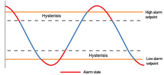
The Y value will be compared with Lo and Hi threshold. Please refer below the graph of alarm processing.
5.4 Payload Data
| Sensor type (1 byte) | Status (1 byte) | 1st - Parameter (4 bytes) |
Meaning of Data in the Payload
| Data | Size (byte) | Bit | Format | Meaning |
| Sensor type = 00000001 | 1 | all | Uint8 | - Sensor type = 00000001 means Sigfox node with analog 0-20mAdc input |
| Status: batt level | 1 | Bit 7 and 6 | Uint8 | Battery capacity in 04 levels 11: battery level 4 (99%) 10: battery level 3 (60%) 01: battery level 2 (30%) 00: battery level 1 (10%) The next - 2 bits : The next - 2 bits : b |
| Status: error | Bit 5 and 4 | Node status 01: error 00: no error |
||
| Status: alarm 1 | Bit 3 and 2 | Alarm status of 1st - parameter (Y value) 11 : Hi alarm 01 : Lo alarm 00 : No alarm |
||
| Status: alarm 2 | Bit 1 and 0 | Spare for alarm status of 2nd - parameter | ||
| 1st - Parameter | 4 | all | float | - Y value (calculated value of measurement) |
6. Configuration
Serial port configuration on computer: 9600 baud, None parity, 1 stop bit.
Reading data by Function 3.
Writing data by Function 16.
During connection with Modbus configuration tool, the Sigfox node will send all data in realtime: Battery, Battery level, Vref, Button status, reedswitch status, PCB temperature, Measured value, alarm status.
Step to configure & check data:
NOTE:
the Modbus configuration can be done in the first 60s after power up the Sigfox node. After 60s, if user can not finish the configuration, user need to reset the power of Sigfox node again.
Step 1: Install the Modbus Configurator Software in the link below
https://filerun.daviteq.com/wl/?id=BaX6RFlaEySKSYHX2j5nYHKBgeWckrox
How to use the Modbus configuration software
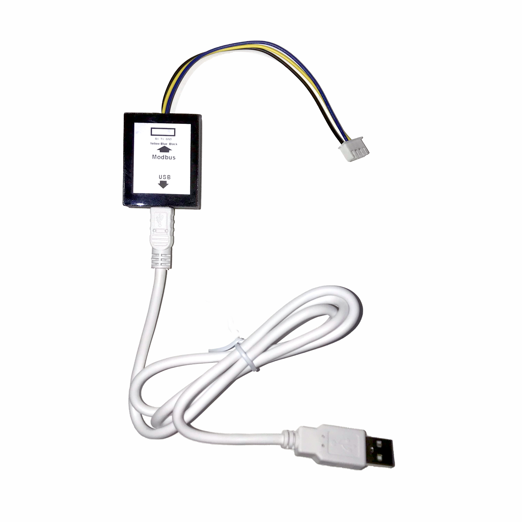
Step 2: Plug the configuration cable to computer via usb port and install the driver;
Step 3: Open the plastic housing;
Step 4: Plug the connector to the configuration port;

Step 5: Insert the battery;

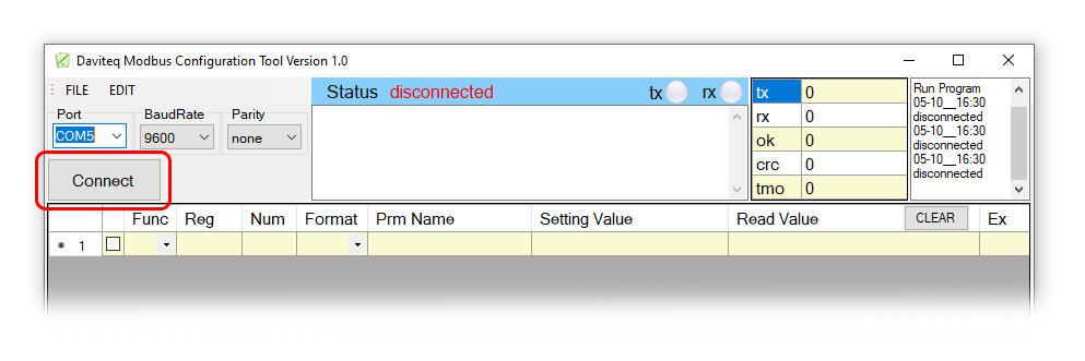
Step 6: Import the configuration file by importing the csv file: Go to MENU: FILE / Import New / => select the file with name CONFIGURATION TEMPLATE FILE FOR SIGFOX WSSFC-AI FW1.9.3.csv (in the link below). Then click Connect;
CONFIGURATION TEMPLATE FILE FOR SIGFOX WSSFC-AI FW1.9.3.csv
| Modbus Register (Decimal) | Modbus Register (Hex) | Function Code | # of Registers | Description | Range | Default | Format | Property | Comment |
| 0 | 0 | 3 | 2 | device info | string | Read | Product name | ||
| 2 | 2 | 3 | 4 | firmware version | 1.0 | string | Read | ||
| 6 | 6 | 3 | 2 | hardware version | 1.0 | string | Read | ||
| 8 | 8 | 3 | 2 | device ID | hex | Read | Product ID | ||
| 10 | A | 3 | 4 | device PAC | hex | Read | Product PAC | ||
| 14 | E | 3 | 1 | sen_type | 1-255 | uint16 | Read | Sensor or Input Type | |
| 15 | F | 3 | 1 | batt level | 0-3 | uint16 | Read | Battery level | |
| 16 | 10 | 3 | 1 | err_status | 0-1 | uint16 | Read | Sensor error code | |
| 17 | 11 | 3 | 1 | prm1 alm_status | 0-2 | uint16 | Read | Alarm status of 1st parameter | |
| 18 | 12 | 3 | 1 | prm2 alm_status | 0-2 | uint16 | Read | Alarm status of 1st parameter | |
| 19 | 13 | 3 | 2 | prm1 value | float | Read | 1st calculated value | ||
| 21 | 15 | 3 | 2 | prm2 value | float | Read | 2nd calculated value | ||
| 23 | 17 | 3 | 1 | batt % | 10%, 30%, 60%, 99% | uint16 | Read | Battery % | |
| 24 | 18 | 3 | 2 | batt volt | 0-3.67 vdc | float | Read | Battery Voltage | |
| 26 | 1A | 3 | 2 | temp | oC | float | Read | RF module temperature | |
| 28 | 1C | 3 | 1 | vref | 0-3.67 vdc | uint16 | Read | Vref of RF Module | |
| 29 | 1D | 3 | 1 | btn1 status | 0-1 | uint16 | Read | Button status, 0: released, 1: pressed | |
| 30 | 1E | 3 | 1 | btn2 status | 0-1 | uint16 | Read | Reedswitch status, 0: opened, 1: closed |
| Modbus Register (Decimal) | Modbus Register (Hex) |
Function Code (Read) |
Function Code (Write) |
# of Registers | Description | Range | Default | Format | Property | Comment |
| 256 | 100 | 3 | 16 | 1 | modbus address | 1-247 | 1 | uint16 |
Read/ Write |
Modbus address of device |
| 257 | 101 | 3 | 16 | 1 | modbus baudrate | 0-1 | 0 | uint16 |
Read/ Write |
Baudrate: 0: 9600, 1: 19200 |
| 258 | 102 | 3 | 16 | 1 | modbus parity | 0-2 | 0 | uint16 |
Read/ Write |
Parity: 0: none, 1: odd, 2: even |
| 259 | 103 | 3 | 16 | 9 | serial number | string |
Read/ Write (PW) |
Product S/N | ||
| 268 | 10C | 3 | 16 | 2 | password for setting | uint32 |
Read/ Write |
Password for setting | ||
| 270 | 10E | 3 | 16 | 1 | Radio Configuration | 1-6 | 4 | uint16 |
Read/ Write |
RC zones selection 1..6 is RCZ1 .. RCZ6 |
| 271 | 10F | 3 | 16 | 1 | tx_power | 20 | int16 |
Read/ Write |
RF Tx power | |
| 272 | 110 | 3 | 16 | 1 | tx_repeat | 0-1 | 1 | uint16 |
Read/ Write |
Number of repeat, 0: 1 time, 1: 3 repeats |
| 273 | 111 | 3 | 16 | 1 | downlink_flag | 0-1 | 0 | uint16 |
Read/ Write |
1: enable Downlink, 0: disable Downlink (Fw v1.0 hasn't got Downlink function) |
| 274 | 112 | 3 | 16 | 2 | cycle_send_data | 900 | uint32 |
Read/ Write |
Data sending cycle, in seconds | |
| 276 | 114 | 3 | 16 | 2 | spare | Spare for future | ||||
| 278 | 116 | 3 | 16 | 1 | alarm_limit | 44 | uint16 |
Read/ Write |
Limit number of alarm sending in 24h | |
| 279 | 117 | 3 | 16 | 1 | spare | Spare for future | ||||
| 280 | 118 | 3 | 16 | 2 | sensor1: sampling_rate | 120 | uint32 |
Read/ Write |
Sensor/Input 1 sampling rate, in seconds | |
| 282 | 11A | 3 | 16 | 2 | sensor1: calc_time | 100 | uint32 |
Read/ Write |
Measurement time of sensor/input 1, in ms | |
| 284 | 11C | 3 | 16 | 2 | sensor2: sampling_rate | 120 | uint32 |
Read/ Write |
Sensor/Input 2 sampling rate, in seconds | |
| 286 | 11E | 3 | 16 | 2 | sensor2: calc_time | 100 | uint32 |
Read/ Write |
Measurement time of sensor/input 2, in ms | |
| 288 | 120 | 3 | 16 | 2 | prm1: a | 1 | float |
Read/ Write |
Constant a for scaling measured value 1 | |
| 290 | 122 | 3 | 16 | 2 | prm1: b | 0 | float |
Read/ Write |
Constant b for scaling measured value 1 | |
| 292 | 124 | 3 | 16 | 2 | prm1: Delta | -1 | float |
Read/ Write |
Delta value for calculated value 1 | |
| 294 | 126 | 3 | 16 | 2 | prm1: High threshold | 100000 | float |
Read/ Write |
Hi Threshold for calculated value 1 | |
| 296 | 128 | 3 | 16 | 2 | prm1: High Hysteresis | 10000 | float |
Read/ Write |
Hysterisis for Hi for calculated value 1 | |
| 298 | 12A | 3 | 16 | 2 | prm1: Low threshold | 0 | float |
Read/ Write |
Lo Threshold for calculated value 1 | |
| 300 | 12C | 3 | 16 | 2 | prm1: Low Hysteresis | 10000 | float | Read/Write | Hysterisis for Lo for calculated value 1 | |
| 302 | 12E | 3 | 16 | 2 | prm1: High cut | 100000 | float |
Read/ Write |
High cut value for calculated value 1 | |
| 304 | 130 | 3 | 16 | 2 | prm1: Low cut | 0 | float |
Read/ Write |
Low cut value for calculated value 1 | |
| 306 | 132 | 3 | 16 | 2 | prm2: a | 1 | float |
Read/ Write |
Constant a for scaling measured value 2 | |
| 308 | 134 | 3 | 16 | 2 | prm2: b | 0 | float |
Read/ Write |
Constant b for scaling measured value 2 | |
| 310 | 136 | 3 | 16 | 2 | prm2: Delta | -1 | float |
Read/ Write |
Delta value for calculated value 2 | |
| 312 | 138 | 3 | 16 | 2 | prm2: High threshold | 100000 | float |
Read/ Write |
Hi Threshold for calculated value 2 | |
| 314 | 13A | 3 | 16 | 2 | prm2: High Hysteresis | 10000 | float |
Read/ Write |
Hysterisis for Hi for calculated value 2 | |
| 316 | 13C | 3 | 16 | 2 | prm2: Low threshold | 0 | float |
Read/ Write |
Lo Threshold for calculated value 2 | |
| 318 | 13E | 3 | 16 | 2 | prm2: Low Hysteresis | 10000 | float |
Read/ Write |
Hysterisis for Lo for calculated value 2 | |
| 320 | 140 | 3 | 16 | 2 | prm2: High cut | 100000 | float |
Read/ Write |
High cut value for calculated value 2 | |
| 322 | 142 | 3 | 16 | 2 | prm2: Low cut | 0 | float |
Read/ Write |
Low cut value for calculated value 2 |
7. Installation
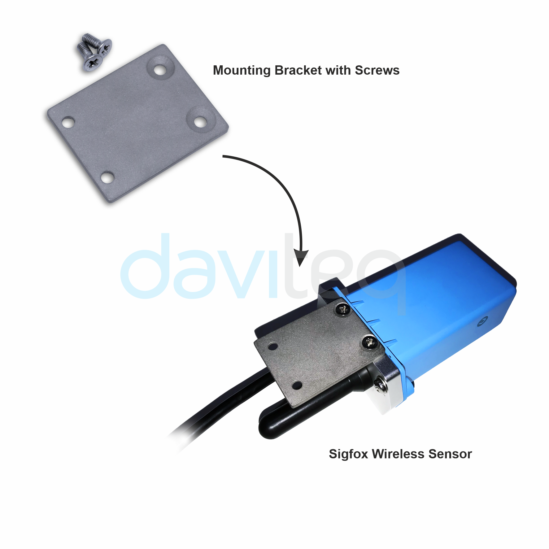
7.1 Mounting bracket installation
The mounting bracket is made from hard metallic material. Following to these steps as the below picture
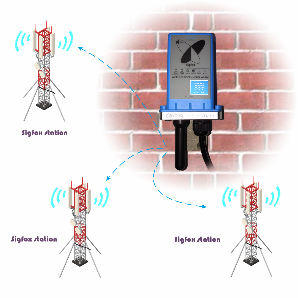
7.2 Installation location
To maximize the distance of transmission, the ideal condition is Line-of-sight (LOS) between the Sigfox sensor and Station. In real life, there may be no LOS condition. However, the Sigfox sensor still communicates with Station, but the distance will be reduced significantly.
ATTENTION:
DO NOT install the Sigfox sensor or its antenna inside a completed metallic box or housing, because the RF signal can not pass through the metallic wall. The housing is made from Non-metallic materials like plastic, glass, wood, leather, concrete, cement…is acceptable.
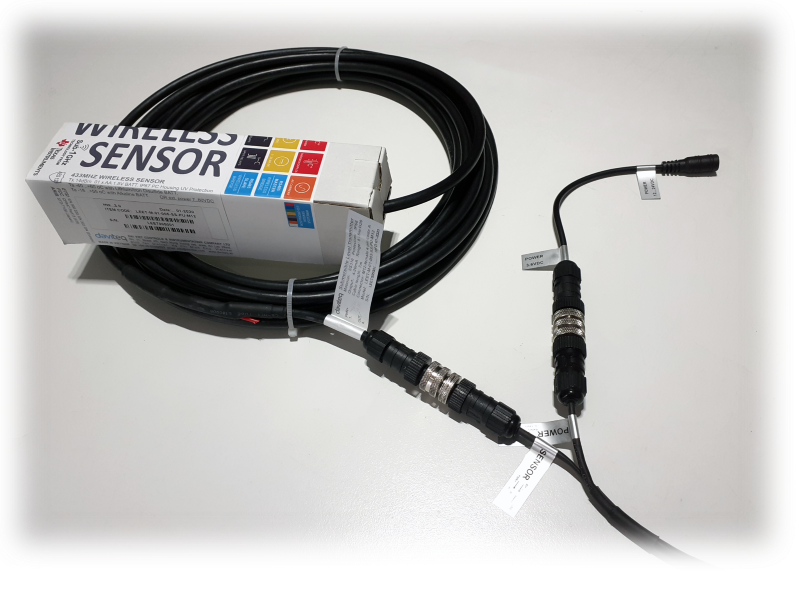
7.3 IO Wiring & Sensor installation
WSSFC-AI can use both Internal and External Power sources. When we plug in an External power source, WSSFC-AI will prioritize using external power. When the external power is disconnected, WSSFC-AI will use the Internal battery power.
WSSFC-AI has two M12 connectors : POWER and SENSOR .
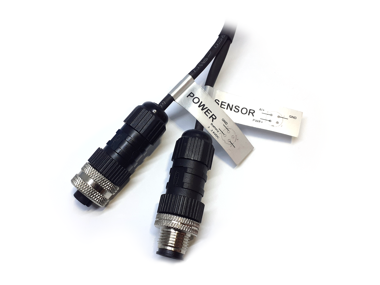
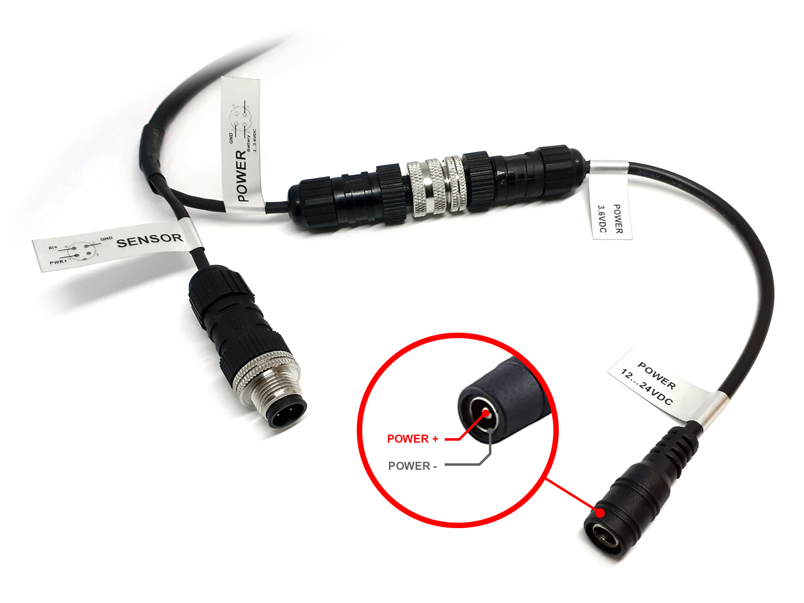
7.3.1 POWER Connector
The POWER connector is an 3..3.6VDC external battery port, so if you want to use this port you must connect the POWER port to the POWER voltage converter cable as shown below.
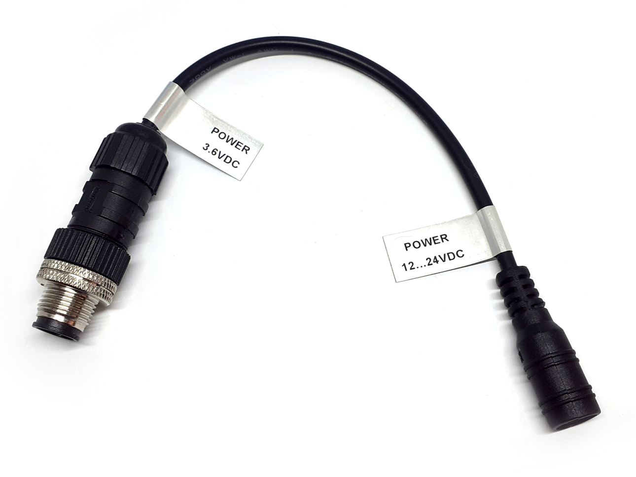
The input power of the voltage converter cable is 12 ... 24VDC with DC jack and the output is 3.6VDC M12 Connector to connect with WSSFC-AI.
NOTE:
Please do not supply the WSSFC-AI POWER port directly with 12 ... 24VDC without voltage converter cable.
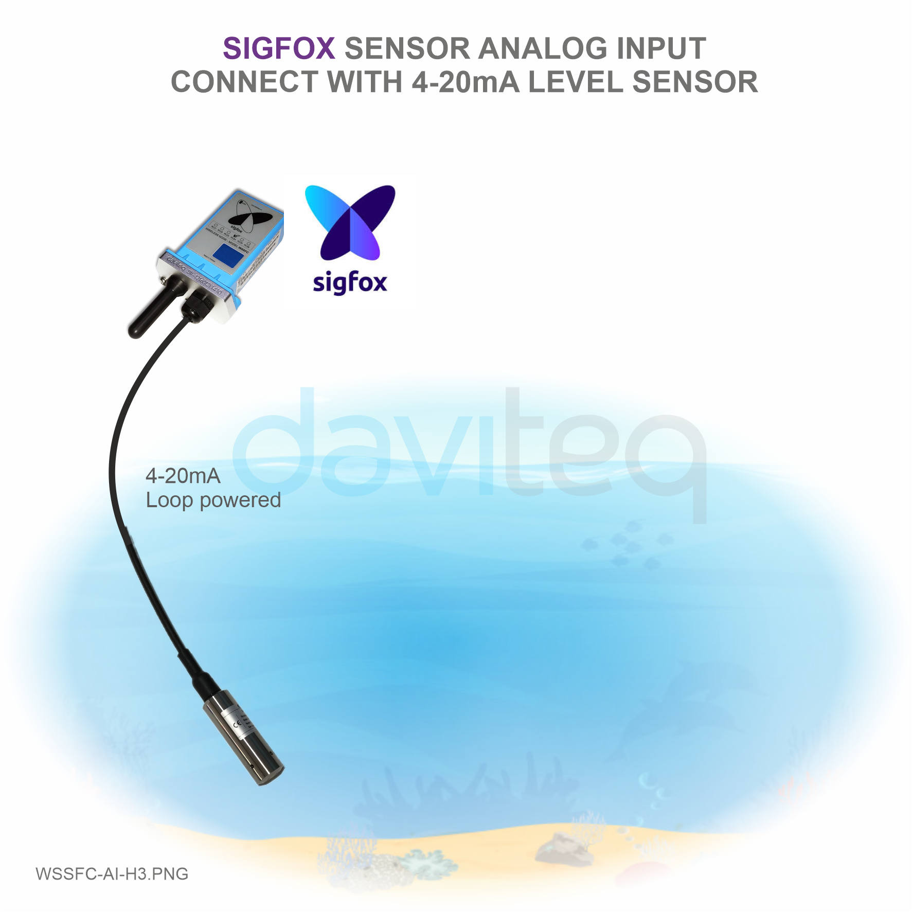
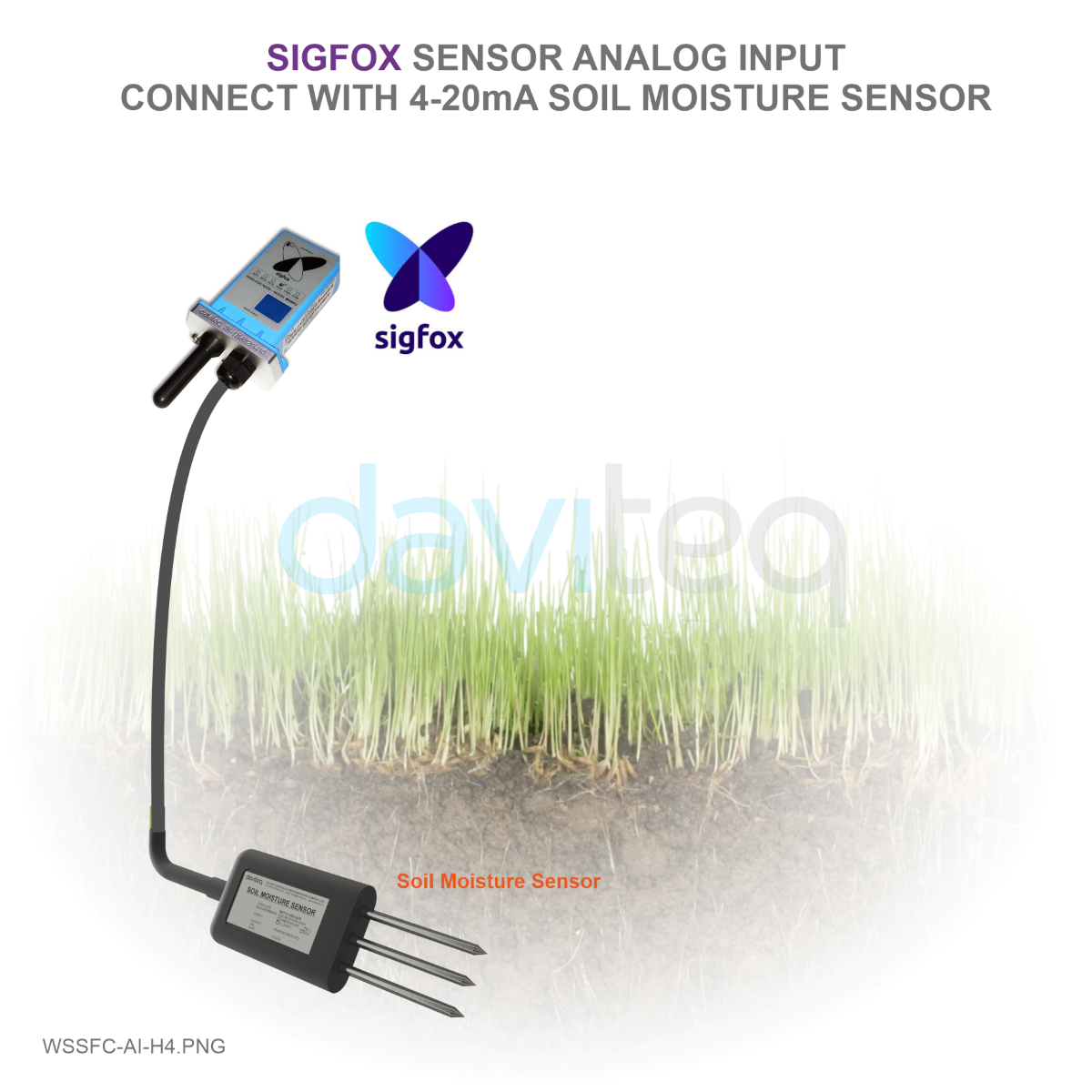
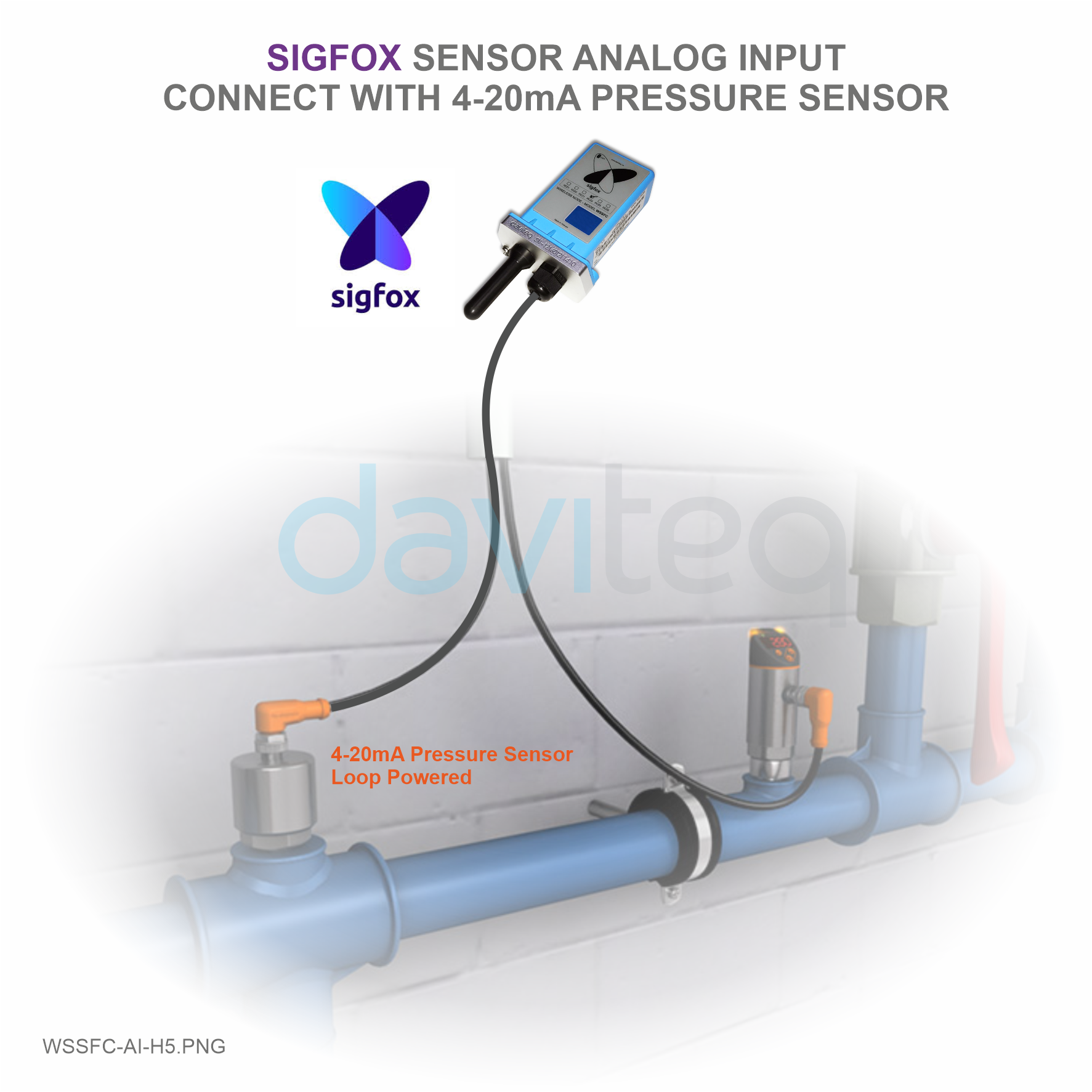
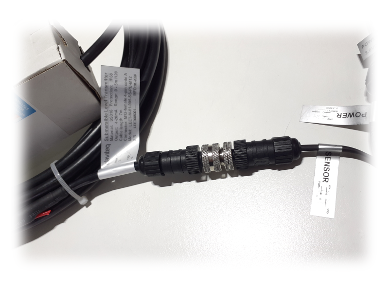
7.3.2 SENSOR Connector
Connect the sensor to WSSFC-AI as shown below
For example: Connect the WSSFC-AI sensor to the Submersible Liquid Level Transmitter via M12 Connector
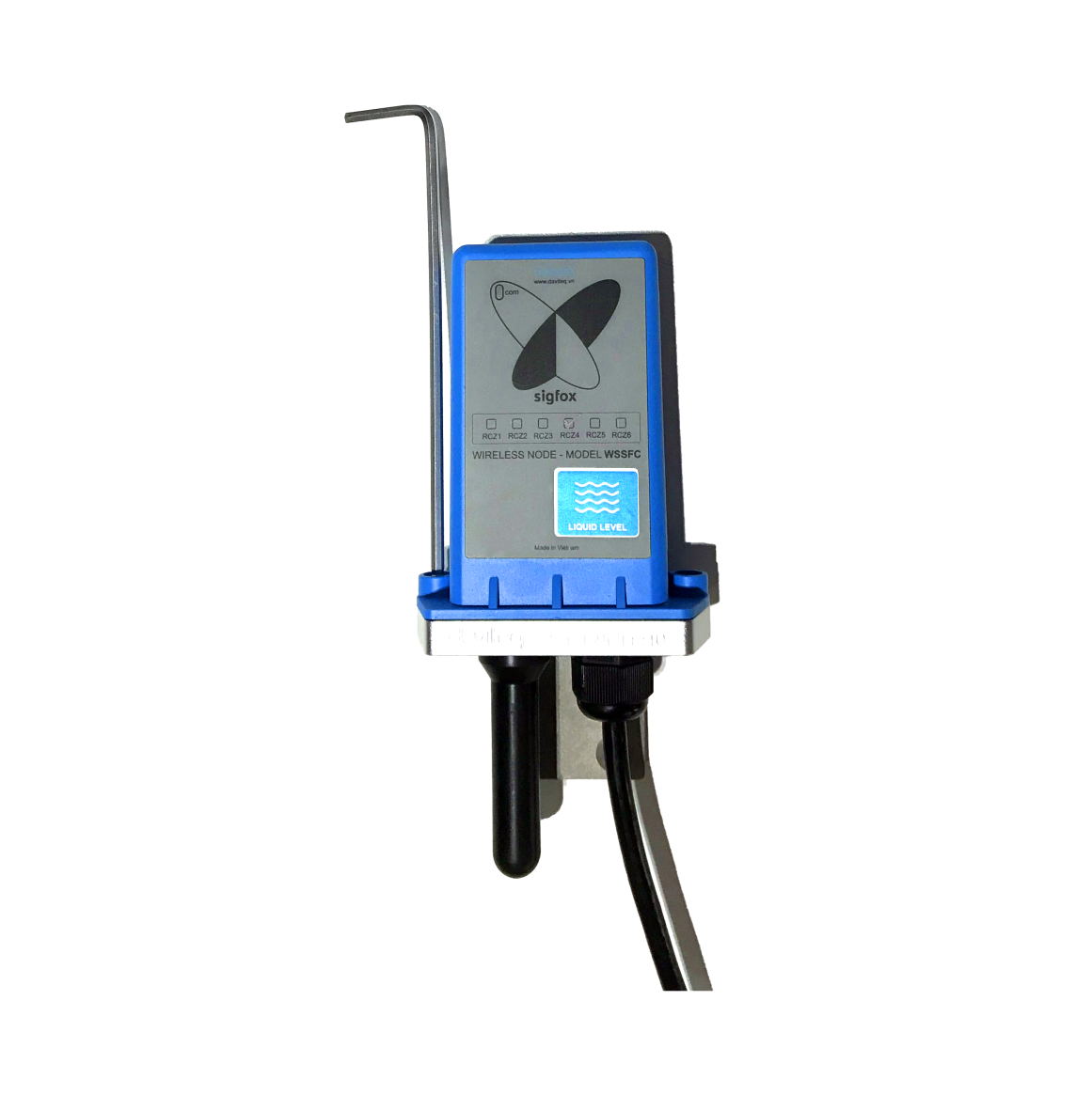
7.4 Power Supply & Battery installation
Steps for battery installation:
Step 1: Using L hex key to unscrew M4 screws at the side of housing
Step 2: Carefully pull out the top plastic housing in the vertical direction
Step 3: Insert the type C battery, please take note the poles of battery
ATTENTION:
REVERSED POLARITY OF BATTERIES IN 10 SECONDS CAN DAMAGE THE SENSOR CIRCUIT!!!
Step 4: Insert the top plastic housing and locking by L hex key
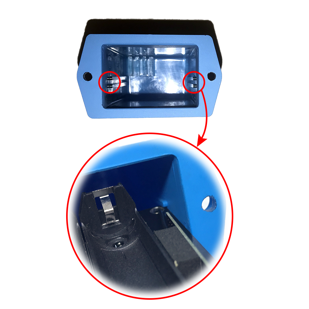
ATTENTION:
When reinstalling the cover, pay attention to put the PCB edge into the middle slot of the box inside as shown below)
8. Troubleshooting
| No. | Phenomena | Reason | Solutions |
| 1 | Node does not send RF to base station periodically, LED does not blink |
|
|
| 2 | Node does not send RF to base station according to the alarm, LED does not blink |
|
|
| 3 | Node does not send RF to base station when activated by the magnetic switch, LED does not blink |
|
|
| 4 | Node has blinked LED when sending RF but the base station cannot received |
|
|
| 5 | Node has sent RF but the LED does not blink |
|
|
| 6 | The value of the sensor is 0 |
|
|
9. Support contacts
|
Manufacturer
Daviteq Technologies Inc Email: info@daviteq.com | www.daviteq.com
|
Distributor in Australia and New Zealand
Templogger Pty Ltd Tel: 1800 LOGGER Email: contact@templogger.net |

No Comments