I. Configuration for iConnector
1.1 Offline configuration process
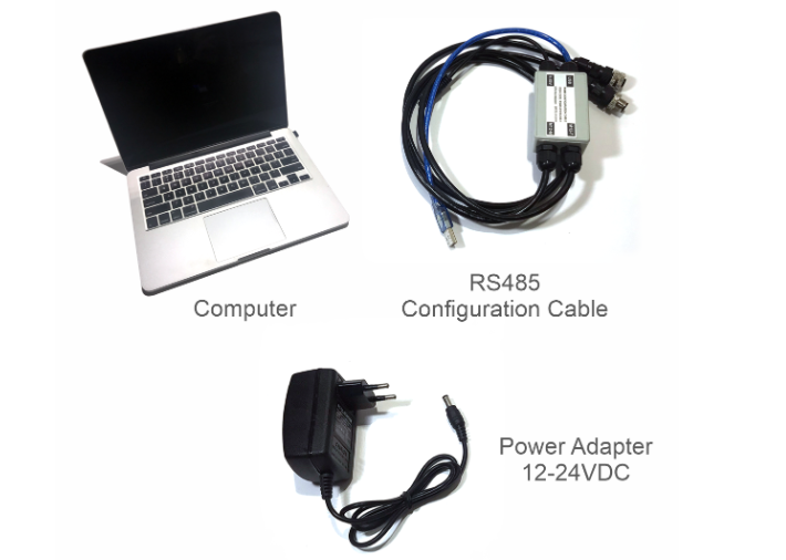
Step 1: Preparation
Prepare some required devices as below
01x A window PC
01x USB-RS485 Configuration Cable
01x Power adapter 12-24VDC
Download the Configuration software in the link
Step 2: Hardware connection
- Connect the USB-A to the PC
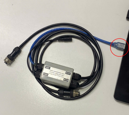
- Connect M12 female of the cable to the iConnector

- Power the iConnector on by connecting DC jack from Power Adapter
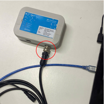
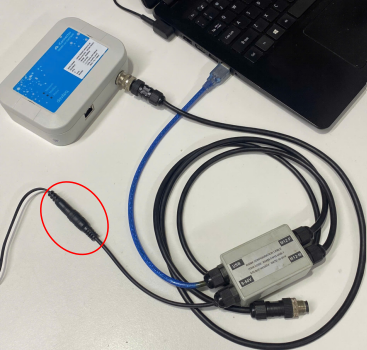
The above steps must be performed in order
Step 3: Configuration the iConnector via iConfig software
- Open the iConfig software, then choose Correct Port, BaudRate and Parity.
Port is based on the PC
BaudRate is 9600
Parity is NONE
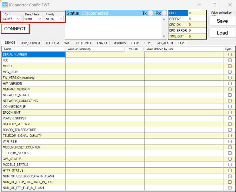

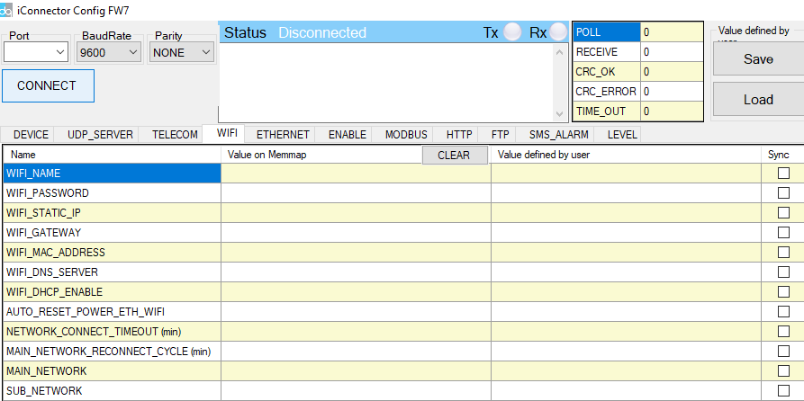
(1) There are 11 configuration tabs on the top banner. Click a tab name to navigate to the corresponding sheet.
(2) The first column displays the parameter names of the iConnector.
(3) The second column shows the current values of the corresponding parameters
(4) The third column is where users can input new configuration values.
(5) After entering the new configuration in the third column, users must tick the corresponding checkbox to apply it. The tick will disappear once the new configuration is successfully written to the iConnector. After that, the updated value will appear in the second column.
1.2 Get iConnector information for Globiots configurations
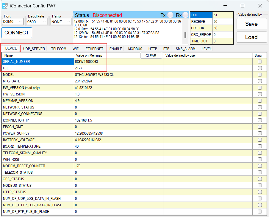
- Click tab Device, get basic information of the iConnector to register it into Daviteq Platform including Serial number & FCC. Note out this information for later iConnector registration on Globiots
1.3 Configuration network parameters for iConnector
* There are many parameters of iConnector to be configured before using.
* However, most of the parameters were configured by the manufacturer.
1.3.1 Configure Globiots server for iConnector
- Click tab UPD_SERVER, input the UDP_SERVER_HOST in the Value defined by user column, then click the check box "Sync" at that row to allow the data to be written to iConnector. Once written successfully, you will see the same data on the "Value" Column.
- Repeat these steps to configure other parameters: UPD_SERVER_PORT, TIME_ZONE configurations.
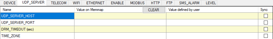
Above Globiots server configurations are usually pre-configured by manufacturer before delivery
1.3.2 Configure the network information for Ethernet iConnector
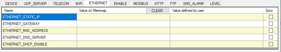
- Click tab Ethernet, input the ETHERNET_STATIC_IP in the Value defined by user column, then click the check box "Sync" at that row to allow the data to be written to iConnector. Once written successfully, you will see the same data on the "Value" Column.
- Repeat this step for ETHERNET_GATEWAY, ETHERNET_DNS_SERVER, ETHERNET_DHCP_ENABLE
- Then click tab WIFI and configure MAIN_NETWORK =2
| Name | Description |
| ETHERNET_STATIC_IP | Ethernet Static IP configuration for iConnector. Example: 192.168.1.30 |
| ETHERNET_GATEWAY | Configure gateway |
| ETHERNET_DNS_SERVER | Configure DNS Server |
| ETHERNET_DHCP_ENABLE |
0 (Off) / 1 (On) If DHCP = 0, it's mean Not using DHCP → Static IP |
Above configurations are applied for Ethernet iConnector
1.3.3 Configure the network information for WIFI iConnector
- Click tab WIFI, input the WIFI_NAME in the Value defined by user column, then click the check box "Sync" at that row to allow the data to be written to iConnector. Once written successfully, you will see the same data on the "Value" Column.
- Repeat this step for WIFI_PASSWORD, WIFI_STATIC_IP, WIFI_GATEWAY, WIFI_DNS_SERVER, WIFI_DHCP_CENABLE
- Configure MAIN_NETWORK = 1
| Name | Description |
| WIFI_NAME | WIFI name network |
| WIFI_PASSWORD | Password of WIFI network |
| WIFI_STATIC_IP | WIFI Static IP configuration for iConnector. Example: 192.168.1.30 |
| WIFI_GATEWAY | Configure gateway |
| WIFI_DNS_SERVER | Configure DNS Server |
| WIFI_DHCP_ENABLE |
0 (Off) / 1 (On) If DHCP = 0, it's mean Not using DHCP → Static IP |
- Repeat these steps to configure other parameters: APN_USERNAME and APN_PASSWORD configurations.
Above configurations are applied for WIFI iConnector
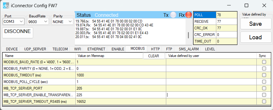
1.4 Configuration Modbus communication parameters for iConnector
Click Modbus tab, configure Modbus communication parameters for RS485 port ( baud rate, parity, stop bit, time out, poll cycle) to match up with Modbus slave device
1.5 Register iConnector on Globiots
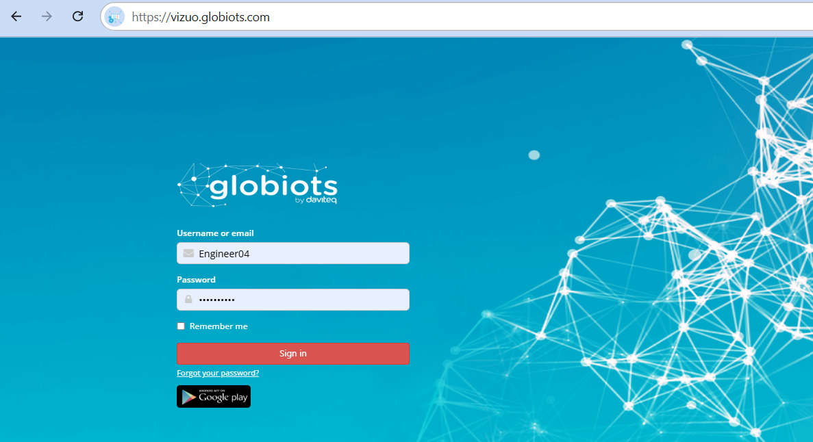
- Access to Vizuo Globiots via the link https://vizuo.globiots.com and login to the system with the username and password supplied Daviteq.
- Register the iConnector into Globiots
- RIGHT-CLICK on the corresponding site in the Organization Chart => New=>Device
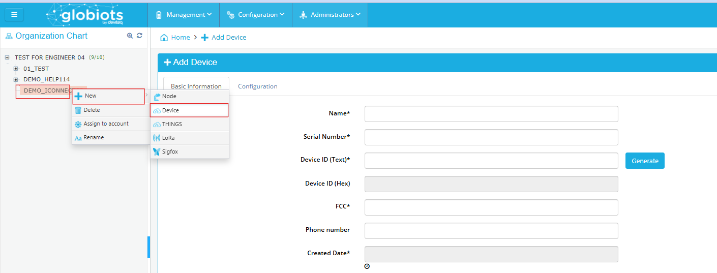
-
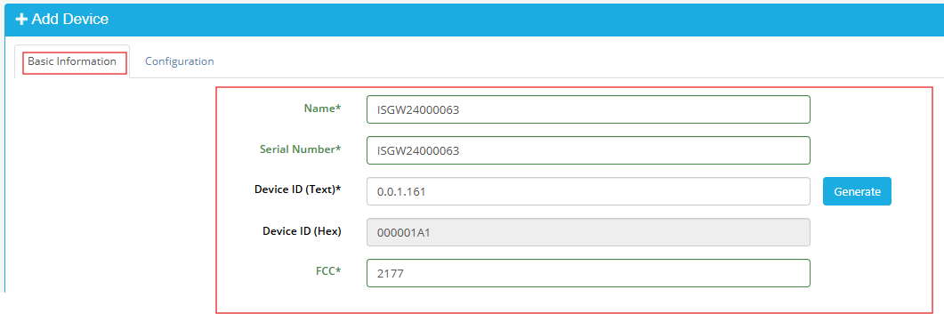
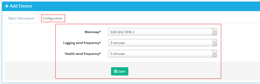
- There are some fields must be configured, including Name, Serial number, Device ID, FCC, Memmap, Logging send frequency, Health send frequency. After the fields were configured => Click Save button
Fields Description Name Optional name, must be 12 characters Serial number Serial number of iConnector
*Taken from step 1.2Device ID Click Generate button in the software FCC FCC of iConnector
*Taken from step 1.2Memmap Choose 4.1.4-9600-RD1 Logging send frequency Choose 5 minutes Health send frequency Choose 5 minutes
- There are some fields must be configured, including Name, Serial number, Device ID, FCC, Memmap, Logging send frequency, Health send frequency. After the fields were configured => Click Save button
1.6 Check iConnector connection on Globiots
- After configure successfully (step 1.1-1.4), the iConnector will connect to Globiots server automatically;
- The LED Network on iConnector will be 1Hz flashing
- Using the provided account of Globiots server, log in to the Globiots system to check the status of iConnector;
+ If connected, the iConnector icon on Organization Chart section will be Blue color;
+ If not connected, the icon is still Grey color;
The iConnector must be powered by configuration tool during this process
No Comments