USER GUIDE FOR ICONNECTOR WIFI
| STHC-ISGWF-WS433-CL-04 |
DEC-2021 |
This document is applied for the following products
| SKU | STHC | HW Ver. | 1.1 | FW Ver. | w1.5_17101 |
| Item Code |
STHC-ISGWF-WS433-CL-04 |
iConnector WIFI, RS485/MODBUSRTU with built-in wireless co-ordinator |
|||
1. Functions Change Log
| HW Ver. | FW Ver. | Release Date | Functions Change |
| 1.1 | w1.5_17101 | DEC-2021 |
2. Introduction
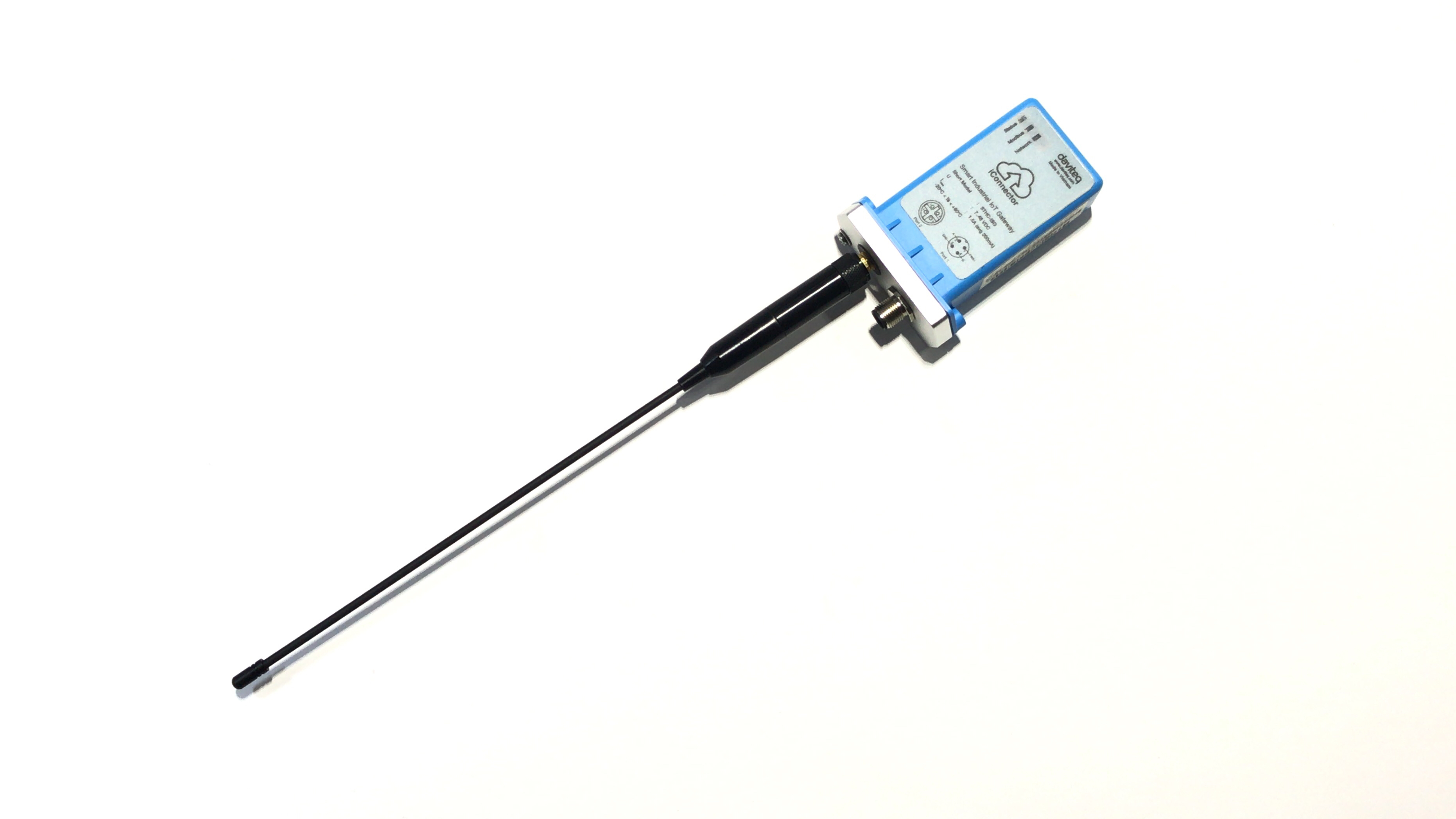
STHC is a Smart IoT Gateway, aka iConnector, a main component in any IoT application. iConnector has a role to connect the real World's things like sensors, meters, ,machines...to server system for data logging, data analytics, monitoring & controls...iConnector support multiple Industrial Fieldbus like Modbus, EthernetIP, Profinet, CClink, Wireless sensor network...It connects to server system via LAN/WAN as Ethernet, WiFi or Cellular.
3. Specification
| Host Communication | 802.11b/g/n, 2.4Ghz, internal Wifi antenna, integrated wireless co-ordinator |
| Host communication supports | TCP/IP, UDP/IP, FTP, HTTPS, SNMP... |
| Fieldbus communcation | ModbusRTU x 01 port, 31 slaves, max 19.2 kpbs |
| Vietnam Type Approval Cerification | QCVN 54:2011/BTTTT, QCVN 15:2015/BTTTT (DAVITEQ B00122019) |
| Power supply | 7..48VDC, avg 200mA, peak 1.5A |
| On-board memory & sensors | 2MB Flash, PCB temperature sensor |
| Electrical connectors | M12, 4-pin, coding A or 9mm Power Plug and USB port |
| Buzzer | Internal buzzer |
| Antenna | Internal Wifi antenna, standard external antenna 0 dbi, option 3dbi, 6dbi, 9dbi. |
| RF frequency band | Free license ISM 433.92Mhz (for others 868, 915, 920Mhz, refer related datasheets) |
| Security Standard | AES-128 |
| Data speed | Up to 50kbps |
| Operating Temperature/Humidity | -20 .. + 60 degC / 95%RH, non-condensing |
| Housing/Protection | Aluminum+Polycarbonate. All version is IP67 protection |
| Dimension | H130xW90xD40 for Ethernet/WiFi versions |
| Net weight | 350 grams Ethernet/WiFi versions |
4. Operation principle
4.1 LED meaning
4.1.1 LED status
| Status | Meaning |
| Fixed ON | iConnector has been supplied with external power |
| Blinking (4 seconds blink 1 time) | Without external power, iConnector is using battery. |
| Blinking (2 seconds blink 1 time) | Low battery warning (Used for type D battery version) |
4.1.2 LED modbus
| Status | Meaning |
| Fixed ON | Modbus connected |
| Blinking (1 seconds blink 2 time) | Connection errors (wrong configuration of baudrate, noise, …) |
| OFF | No modbus connection |
4.1.3 LED network
| Status | Meaning |
| Fixed ON | Connecting with Globiots |
| Blinking (1s change state) | Initializing wifi generator, waiting for configuration via phone or modbus tool (For iConnector wifi) |
| OFF | No connection with Globiots |
4.2 Memory Map
|
Address |
Size (bytes) |
Memory type |
Read/Write |
Description |
|
0-0x1FFF |
8096 |
FLASH |
R/W |
Save active configuration, do not allow log, realtime. |
|
0x2000-0x22FF |
768 |
RAM |
R |
Save data read from modbus slaves. |
|
0x2300-0x24FF |
512 |
RAM |
R |
The intrinsic data of iConnector |
|
0x3000-0x30FF |
256 |
RAM |
R/W |
|
|
0x5000-0x50FF |
256 |
FLASH |
R/W |
|
|
0x6000-0x6FFF |
4096 |
RAM |
R |
Save data read from modbus slaves |
- Data address area: 0x2000-0x22FF (768 bytes), and 0x6000-0x6FFF (4096 bytes).
- Controller address area: 0x3000-0x30FF (256 bytes, without flash storage), and 0x5000-0x50FF (256 bytes, with flash storage).
Address area 0x5000-0x50FF
- 256 bytes;
- Save in flash (when power is lost, will keep the same value);
- Allows reading, and writing from Globiots;
- Allow log (realtime);
- Allows Modbus write to Slaves;
- It is not allowed to store data read from Modbus Slaves.
NOTE:
Flash recorded about 100,000 times will be damaged so do not use this area to contain the value is changed several times.
4.3 Logged data
- Up to 20 different log cycles;
- 320 log parameters maximum for all log cycles.
- Up to 120 log parameters per log cycle.
4.4 Modbus
- Support modbus RTU.
- Address slave 1… 247.
- It is not allowed to set address slave = 0.
- Baudrate 4800/9600/19200.
- Parity none / odd / even.
- Up to 100 modbus instructions.
- The address area for storing read data: 0x2000-0x22FF (768 bytes), and 0x6000-0x6FFF (4096 bytes).
- Controller address area: 0x3000-0x30FF (256 bytes, without flash storage), and 0x5000-0x50FF (256 bytes, with flash storage).
4.5 Realtime
- Read up to 200 parameters.
- If all parameters are float (4 bytes) then read up to 140 parameters.
- The fastest realtime sending frequency is 1 second.
4.6 Alarm
- Up to 28 alarms.
- Supported data types:
|
PrmType |
Description |
# Byte |
Range |
|
1 |
BYTE |
1 |
0 to 255 |
|
2 |
UINT16 |
2 |
0 to 65,535 |
|
3 |
UINT32 |
4 |
0 to 4,294,967,295 |
|
4 |
FLOAT |
4 |
-/+3.40282347 * (10^+38) |
|
5 |
INT16 |
2 |
-32,768 to 32,767 |
|
6 |
INT32 |
4 |
-2,147,483,648 to 2,147,483,647 |
4.7 Event
- The event table is 1024 bytes.
- The number of events depends on the short length of the event configured.
- Supported data types:
|
PrmType |
Description |
# Byte |
Range |
|
1 |
BYTE |
1 |
0 to 255 |
|
2 |
UINT16 |
2 |
0 to 65,535 |
|
3 |
UINT32 |
4 |
0 to 4,294,967,295 |
|
4 |
FLOAT |
4 |
-/+3.40282347 * (10^+38) |
|
5 |
INT16 |
2 |
-32,768 to 32,767 |
|
6 |
INT32 |
4 |
-2,147,483,648 to 2,147,483,647 |
4.8 Health data
- Every 15 seconds send health pack 1 time.
5. Configure using the iConfig app on the phone
After supplying power the iConnector via M12 connector, only configure using the iConfig app within the first 5 minutes.
Use app on android phone then configure the Wifi Name and Password that iConnector Wifi will connect to.
Please refer to how to configure using iConfig app with the following link:
iConfig Mobile app for Android
6. Connect iConnector to Templogger Pro Server System
6.1 Login
Please visit the link to the login page: Templogger Pro - Login
If you do not have an account on the Templogger Pro Server System, please contact the Templogger Pro technical staff for assistance.

6.2 Add iConnector STHC to Templogger Pro Server System
To close or open “Organization Chart” panel, you can click  on left corner of screen Organization Chart page includes all Node and Device in system:
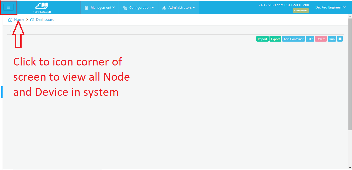
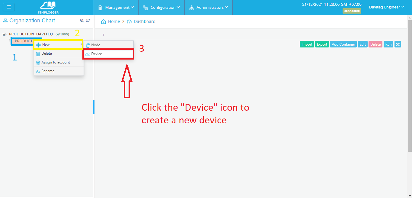
Right click on Node name, menu of Node displays:
• New: Create new Node, Device
• Delete: Delete Node
• Assign to account: Assign Node and sub-Node to account
• Rename: Change name of Node
To create a new Device:
(1) Select Node
(2) Right click and select “New”
(3) Click “Device” to create a new Device
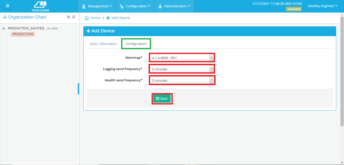
(4) A box appears:
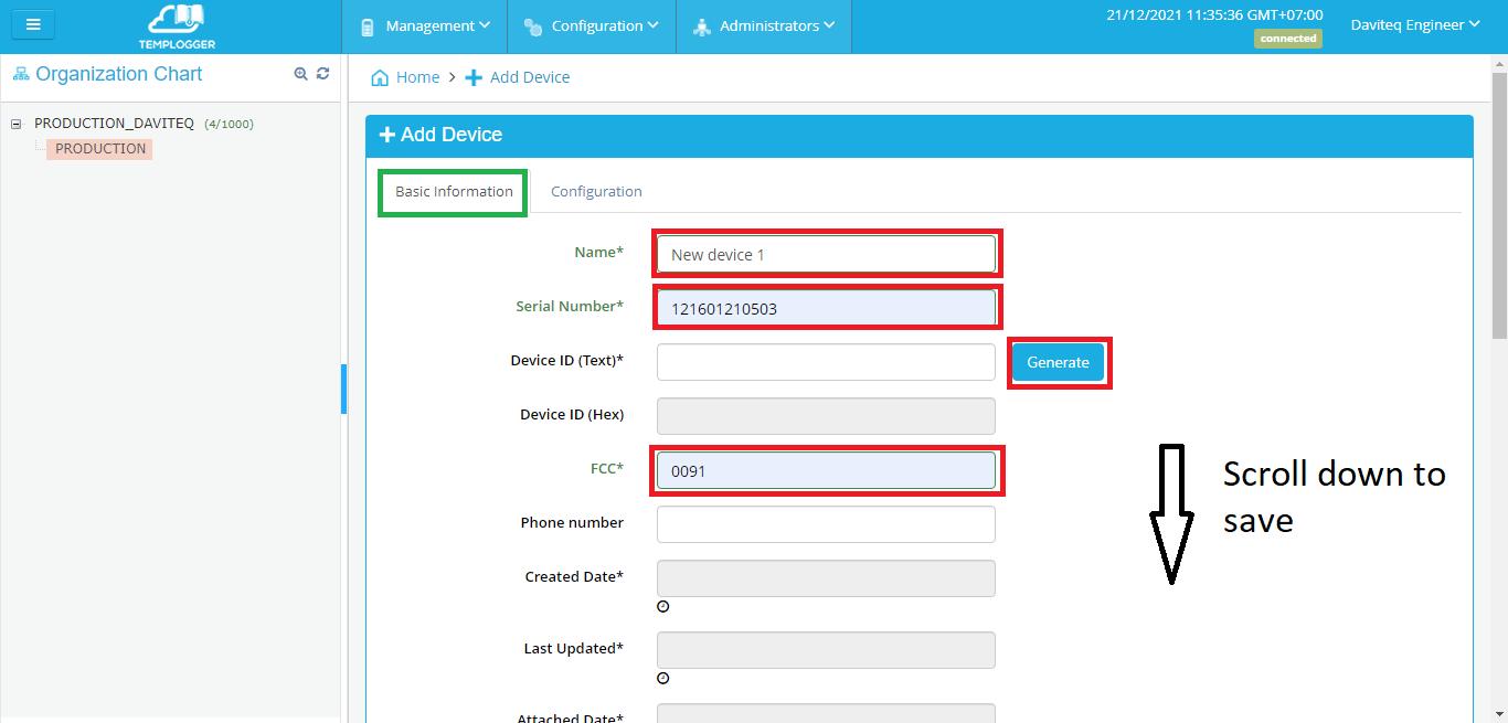
• Enter parameters of Device:
• Name: Name of Device (require 12 characters)
• Serial Number: provided by manufacturer (require 12 characters)
• Click “Generate” button to create Device ID or enter ID directly
• FCC: provided by manufacturer (require 4 characters)
• Click “Save” button to continue. A box appears:
Serial Number , FCC : Please contact the Templogger Pro technical staff for assistance.
(5) A box appears after save:
Select the same image and save. After save again at tab "Basic information".
Confirm the request and enter the account to create a new device.
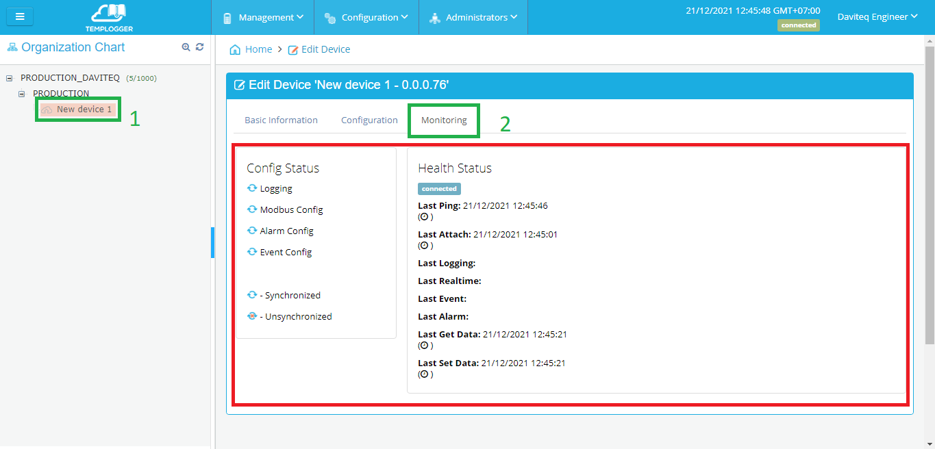
6.3 Check health a new Device
To check health a new Device:
(1) Select Node.
(2) Select Monitoring Tab.
• Health Status: display Connection status between iConnector and server ( Connected/Waiting for connect/Disconnected)
• Config Status: display synchronization status (Synchronized or Unsynchronized)
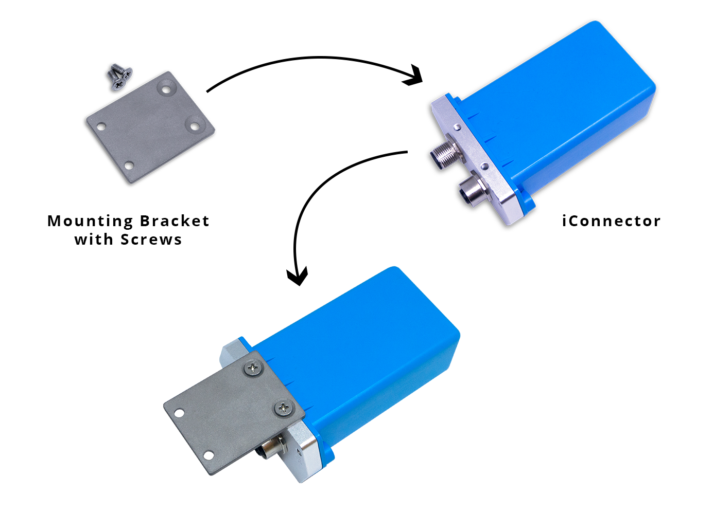
7. Installation
7.1 Installation location
Installed on a wall or in non-metal box. The bracket will be fixed on the wall or material with a planar surface with 2 x M4 screws;
ATTENTION:
DO NOT install the iConnector inside a completed metallic box or housing, because the RF signal can not pass through the metallic wall. The housing is made from Non-metallic materials like plastic, glass, wood, leather, concrete, cement…is acceptable.
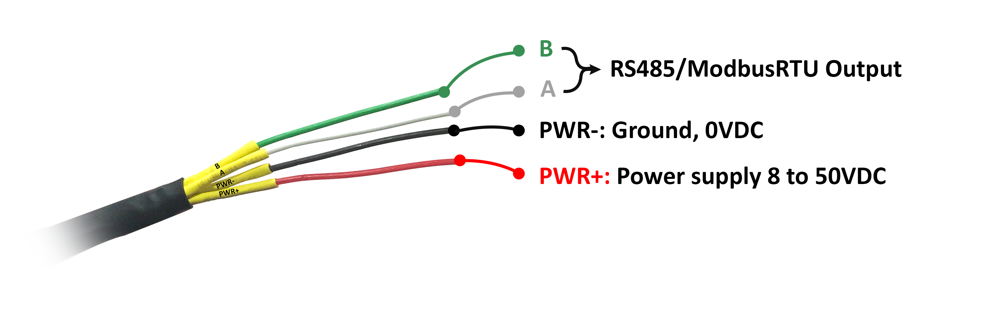
7.2 IO Wiring
7.2.1 Connect Power Supply and Modbus
- Connect PWR+ and PWR- to 7..48VDC power supply via M12 Male connector
- Connect A and B to RS485 connection.
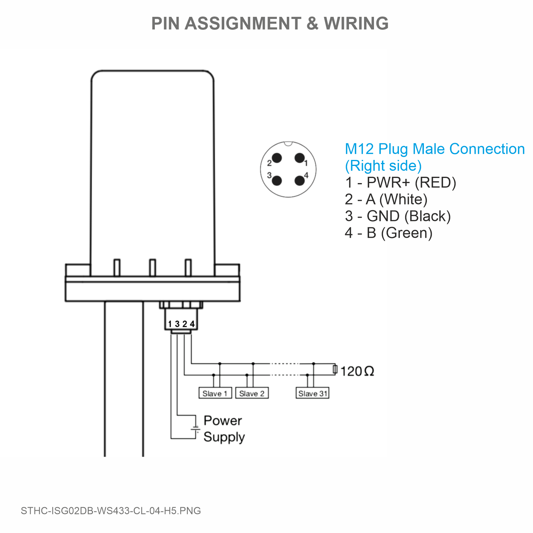
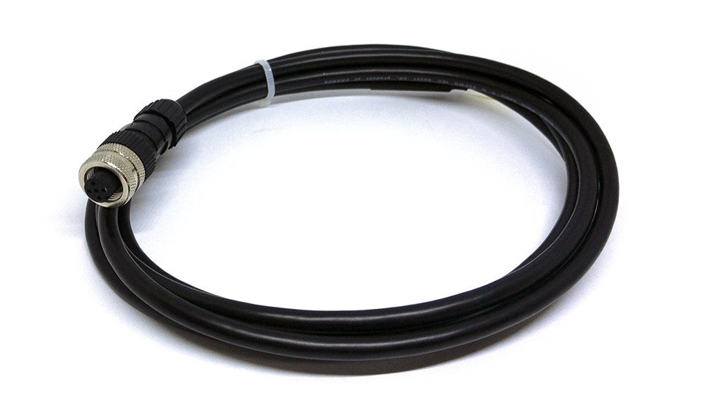
Use M12 female connection cable to connect to iConnector
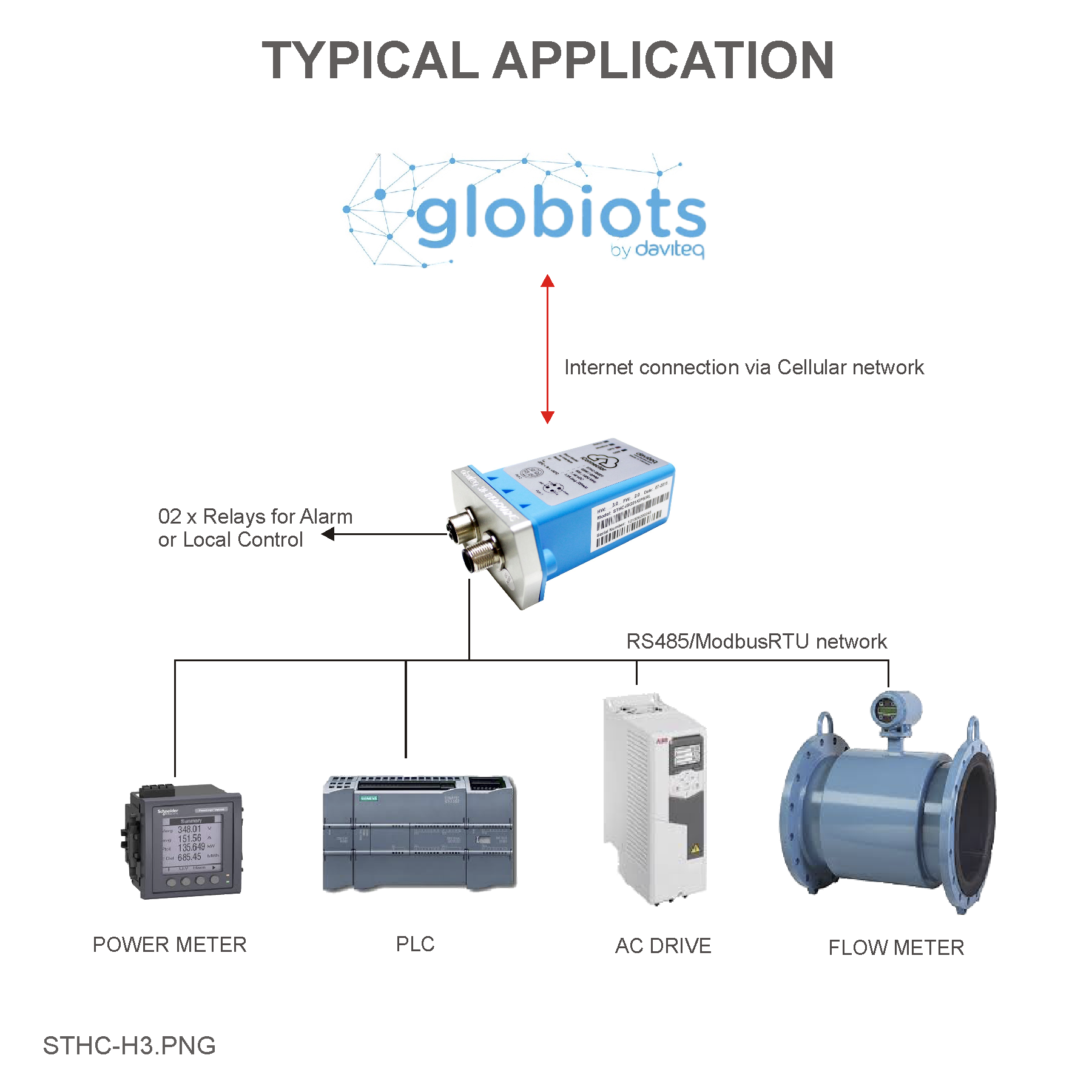
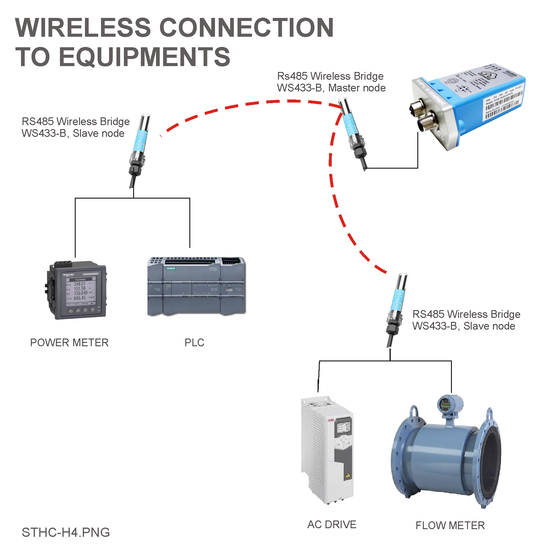
8. Example application
 |
 |
9. Troubleshooting
| No. | Phenomena | Reason | Solutions |
| 1 | Data does not go to server, N/A | iConnector lost connection with server |
|
| 2 |
|
|
|
| 3 | The data posted on Globiots is wrong, the phenomenon of value is changed abnormally continuously | Configuration parameter & modbus command is wrong | Check and correctly configure parameters & modbus commands |
| 4 |
|
Lost power iConnector | Check iConnector power supply |
| 5 | Led network does not light |
|
|
10. Support contacts
|
Manufacturer
Daviteq Technologies Inc Email: info@daviteq.com | www.daviteq.com
|
Distributor in Australia and New Zealand
Templogger Pty Ltd Tel: 1800 LOGGER Email: contact@templogger.net |

No Comments