USER GUIDE FOR ICONNECTOR 3G STHC-B-ISG02DB-03
| STHC-B-ISG02DB-03-MN-EN-01 |
Jul-2020 |
This document is applied for the following products
| SKU | STHC-B | HW Ver. | 1.1 | FW Ver. | 1.4 |
| Item Code | STHC-B-ISG02DB-03 |
Iconnector 3g Dualband, internal antenna, 1 x battery size D 3.6VDC and external DC power, 1 x pulse input, 1 x 4-20mA input with 15v supply to external sensor, Ip67, 1 x M12-M for power, 1 x M12-F for IO |
|||
1. Functions Change Log
| HW Ver. | FW Ver. | Release Date | Functions Change |
| 1.1 | 1.4 | Jun-2020 |
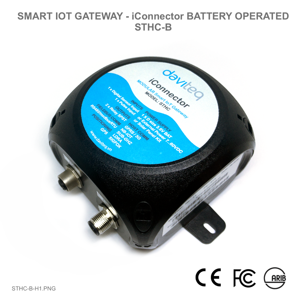
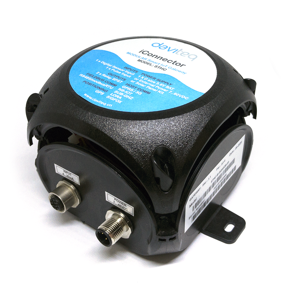
2. Introduction
STHC-B is same as STHC, is a Smart IoT Gateway, aka iConnector, a main component in any IoT application. However, STHC-B is operated by a Primary battery 3.6V, suitable for applications where no grid power like Water pipeline, water network...In addition, STHC-B is also powered by external power supply 7..48VDC or Solar panel system. STHC-B has built-in 1 Pulse input to read the Pulse from flow meter...and 01 Digital input can connect to Pressure sensor, Level, Temperature, Humidity... Data will be sent back to server for data logging, data analytics, monitoring & controls...With Ultra low power design, it can uses 01 battery size D for up to 05 years (depend on configuration of data logging and sending).
3. Specification
| Host Communication | GPRS Quadband/3G-Dual band/NB-IoT, internal antenna |
| Host communication supports | TCP/IP, UDP/IP, FTP, HTTPS, SNMP... |
| Vietnam Type Approval Cerification | QCVN 54:2011/BTTTT, QCVN 15:2015/BTTTT (DAVITEQ B00122019) |
| Analog Input | 1 x 4-20ma input with 15v supply to external sensor |
| Pulse Input | 1 x Pulse input with counting function, dry-contact, max 1Hz, auto-reset counter when reaching 9 digits |
| Digital Sensor Input | 1 x Digital sensor input for DULP sensor type (Digital Ultra Low Power ), M12 connector, IP67 |
| Battery Supply | 1 x D size battery holder, 3.6VDC |
| External Power Supply | 7..48VDC, avg 200mA, peak 1.5A |
| Back-up battery | Lithium Super Capacitor (to alert shortage of power supply) |
| On-board logging | 2MB Flash |
| SIM slot | 01 x micro-SIM |
| Operating Temperature | -20 .. + 85 degC (refer temperature working range of Battery being used) |
| Dimension | H110xW110xD70 |
| Housing | Poly-carbonate housing, IP67, wall mount pads |
| Net weight | < 250 g (excluded Battery and Sensor) |
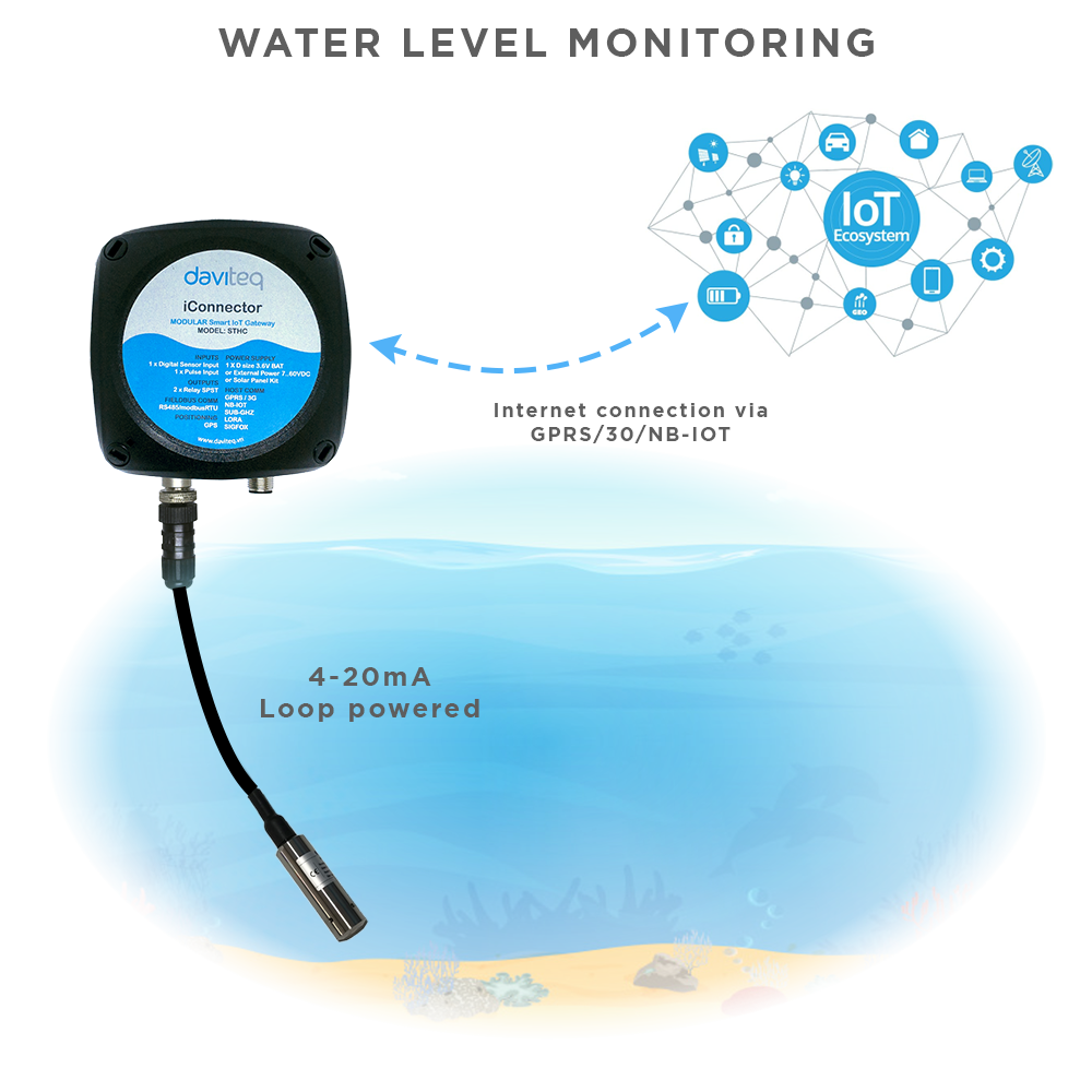
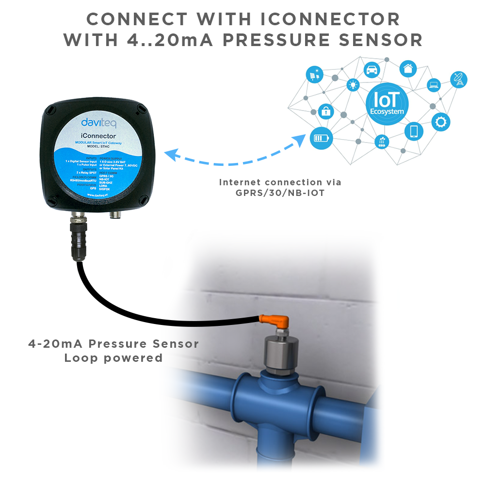
4. Applications
 |
 |
 |
 |
5. Operation principle
5.1 Process of measurement
When the sensor sampling interval is reached, for example, 2 minutes (Battery Mode), iConnector will wake up and turn ON the power to supply power to the external sensor to start measuring. Depending on the type and characteristics of the external sensor, it may take a certain time to complete the measurement.
For example, the measurement time is 200mS, after this time, iConnector will read the value of the sensor by I2C, it will switch the power OFF to the external sensor to save energy.
If we supply external power through M12 connector, iConnector will run realtime.
After reading the sensor value, the raw data is X, it can be scaled to any technical value by the following formula:
Y = aX + b
Where
X: the raw value from sensor
Y: the calculated value for parameter 1's value or parameter 2's value
a: constant
b: constant
So, if there is no user setting for a and b ==> Y = X
The Y value will be compared with Lo and Hi threshold.
5.2 Configuration via Memory map
We can configure online using the memmaps shown in the table below:
|
ADDRESS (in decimal) |
ADDRESS (in hex) |
LENGTH (in byte) |
TYPE | NAME | DESCRIPTION | UNIT | Server |
| 8960 | 2300 | 4 | float | power supply | External power supply voltage | volt | R |
| 8964 | 2304 | 4 | float | battery | Battery voltage | volt | R |
| 8982 | 2316 | 1 | byte | gsm signal quality | GSM signal strength | R | |
| 902 | 386 | 4 | uint32 | I2C: sample_rate (sec) |
sensor reading cycle, e.g: 60 seconds. |
sec | R/W |
| 906 | 38A | 2 | uint16 | I2C: calc_time (ms) | time of supplying power to the sensor before reading the I2C, e.g: 200 ms. | ms | R/W |
| 908 | 38C | 2 | uint16 | I2C: num_of_sample |
The number of ADC samples taken in a reading of sensor data, the more samples the longer the sensor reading time. For example: 8 samples with each sample have a reading time of 10ms, then the total sampling time is 80ms. |
||
| 910 | 38E | 4 | float | I2C: prm1_a |
The a constants after calculation according to the formula |
R/W | |
| 914 | 392 | 4 | float | I2C: prm1_b |
The b constants after calculation according to the formula |
R/W | |
| 918 | 396 | 4 | float | I2C: prm1_hi_cut |
Cut the upper threshold of I2C e.g: If prm1_scaled_value > prm1_hi_cut then prm1_scaled_value = prm1_hi_cut |
R/W | |
| 922 | 39A | 4 | float | I2C: prm1_lo_cut |
Cut the lower threshold of I2C e.g: If prm1_scaled_value < prm1_lo_cut then prm1_scaled_value = 0. |
R/W | |
| 9398 | 24B6 | 1 | uint8 | I2C: sensor type | Sensor type = 20 means that the I2C sensor reads 4-20mA | R/W | |
| 9399 | 24B7 | 1 | uint8 | I2C: error status | if error status = 0, it means the sensor reading is OK, else error status = 1 is faulty. | R/W | |
| 9400 | 24B8 | 4 | float | I2C: prm1_scaled_value |
The measured value has been scaled for the sensor Formula to calculate scale: prm1_scaled_value = prm1_raw_value * prm1_a + prm1_b |
R/W | |
| 9408 | 24C0 | 4 | float | I2C: prm1_raw_value |
Raw sensor value read from I2C |
R/W |
5.3 Offline configuration
5.3.1 Connection
First, you need to prepare

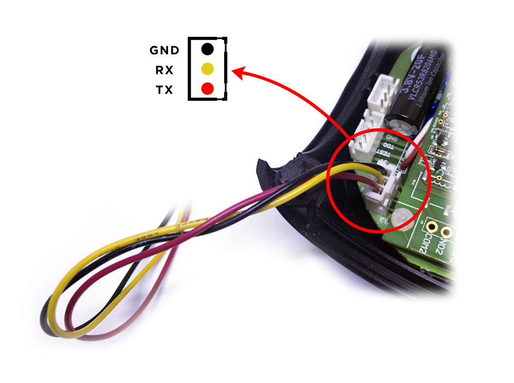
- Step 1: Open the cover of the iConnector
- Step 2:Connect the Configuration Cable to the UART Port in iConnector
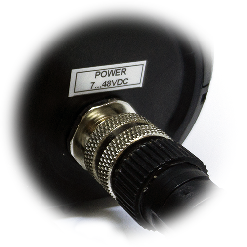
- Step 3: Power the iConnector via M12 male connector on iConnector

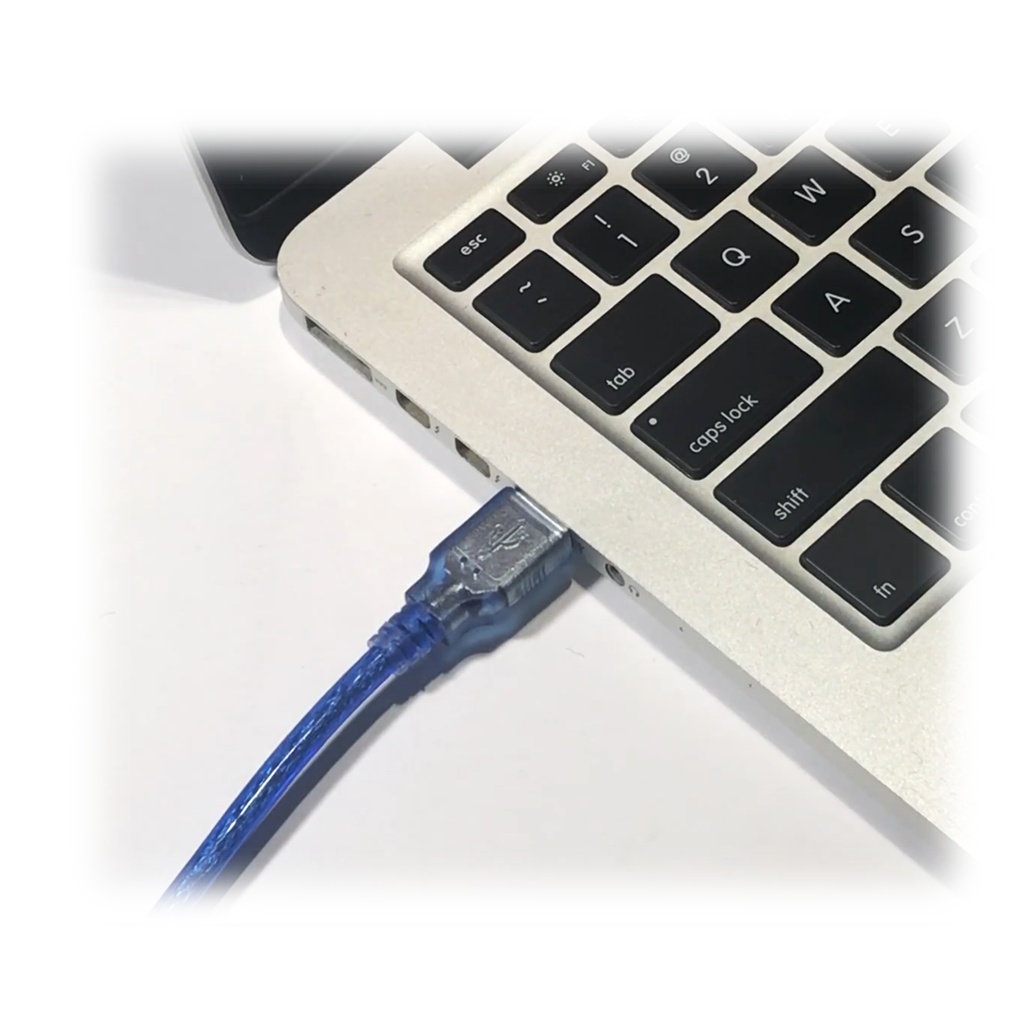
- Step 4: Connect the USB port of the Configuration Cable to the Computer
5.3.2 Configuration tool
- You can download Configuration Tool with the following link:
https://filerun.daviteq.com/wl/?id=s5QApxosVNZLbATxi0TtKVoJX4ms1PxD
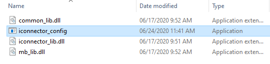
- Unzip file and run file application "iconnector_config"
- Choose COM Port (the Port which is USB cable plugged in)
- Set the BaudRate: 9600, Parity: none
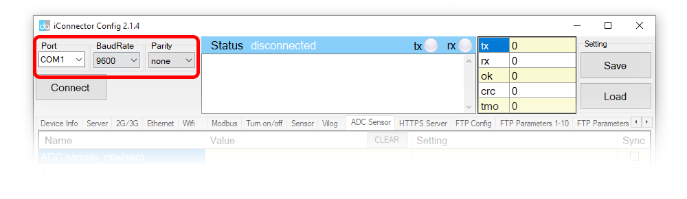
- Click “ Connect “ untill the Status displays “disconnected” to “connected“. It means the iConnector is being connected with computer;
- Configuration parameters:
-
- Write in the Setting column the data to be configured into iConnector
- Click Sync to synchronize data into iConnector
- After synchronizing the data into iConnector, if the data displayed in the Value column shows the corresponding data, the configuration is completed.
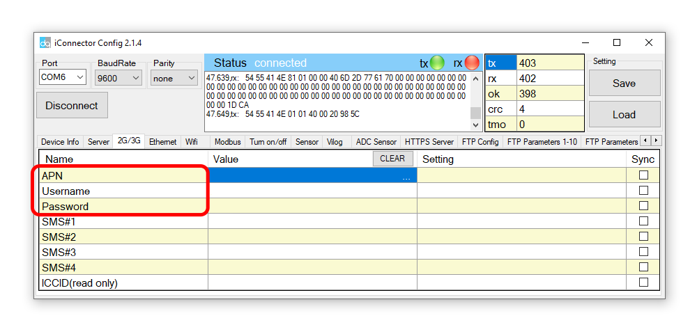
5.4 SIM configuration
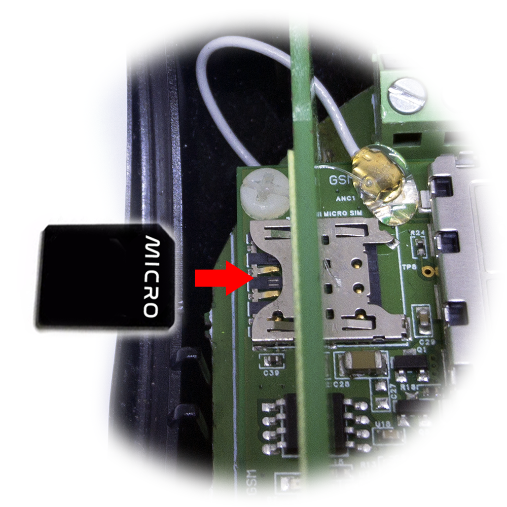
iConnector 3G uses micro-SIM and needs to be configured to use the data network
- Open iConnector cover and install the SIM card

- Based on the information of the mobile carrier that provides the SIM card, we configure data such as APN, username, password on the 2G/3G tab

5.5 Configure sensor parameters on the iConnector
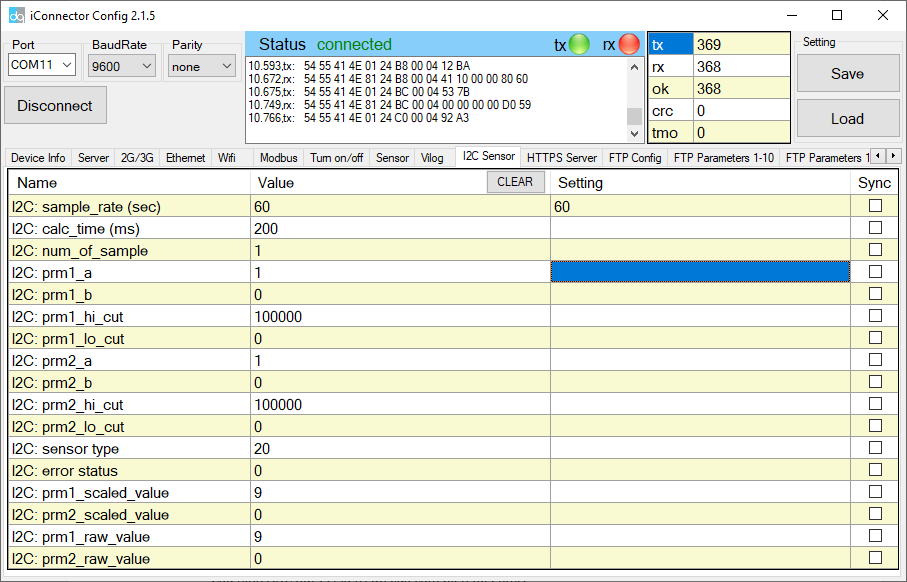
5.5.1 Configure I2C_Sensor tab
We configure the parameters of 4-20mA sensor in I2C Sensor tab:
| I2C: sample_rate (sec) |
sensor reading cycle, e.g: 60 seconds. |
| I2C: calc_time (ms) | time of supplying power to the sensor before reading the I2C, e.g: 200 ms. |
| I2C: num_of_sample |
The number of ADC samples taken in a reading of sensor data, the more samples the longer the sensor reading time. For example: 8 samples with each sample have a reading time of 10ms, then the total sampling time is 80ms. |
| I2C: prm1_a |
The a constants after calculation according to the formula |
| I2C: prm1_b |
The b constants after calculation according to the formula |
| I2C: prm1_hi_cut |
Cut the upper threshold of I2C e.g: If prm1_scaled_value > prm1_hi_cut then prm1_scaled_value = prm1_hi_cut |
| I2C: prm1_lo_cut |
Cut the lower threshold of I2C e.g: If prm1_scaled_value < prm1_lo_cut then prm1_scaled_value = 0. |
| I2C: sensor type | Sensor type = 20 means that the I2C sensor reads 4-20mA |
| I2C: error status | if error status = 0, it means the sensor reading is OK, else error status = 1 is faulty. |
| I2C: prm1_scaled_value |
The measured value has been scaled for the sensor Formula to calculate scale: prm1_scaled_value = prm1_raw_value * prm1_a + prm1_b |
| I2C: prm1_raw_value |
Raw sensor value read from I2C |
5.5.2 Operation mode of iConnector with different power sources
When iConnector only works with D type battery:
- 3G network will turn off, only when the 3G data sending cycle is turned on to send data, after sending it will turn off.
- Not sending a ping leads to iConnector not running realtime, unable to sync from the server.
- Unable to configure from iConfig software.
When iConnector is connected to 7-48VDC power source:
- 3G network is always on, running Ping and ready to receive realtime, synchronization, running full of features.
- Can be configured from iConfig software.
6. Installation
6.1 iConnector Installation
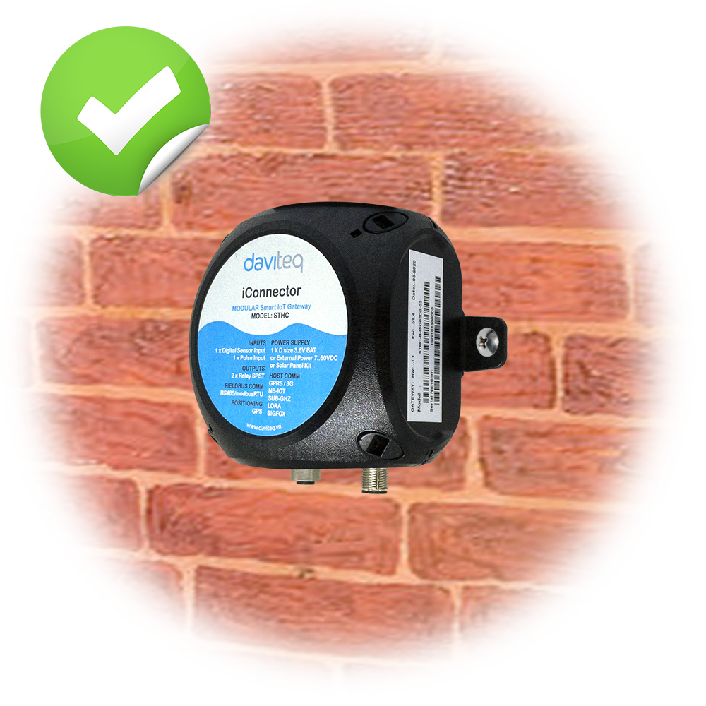
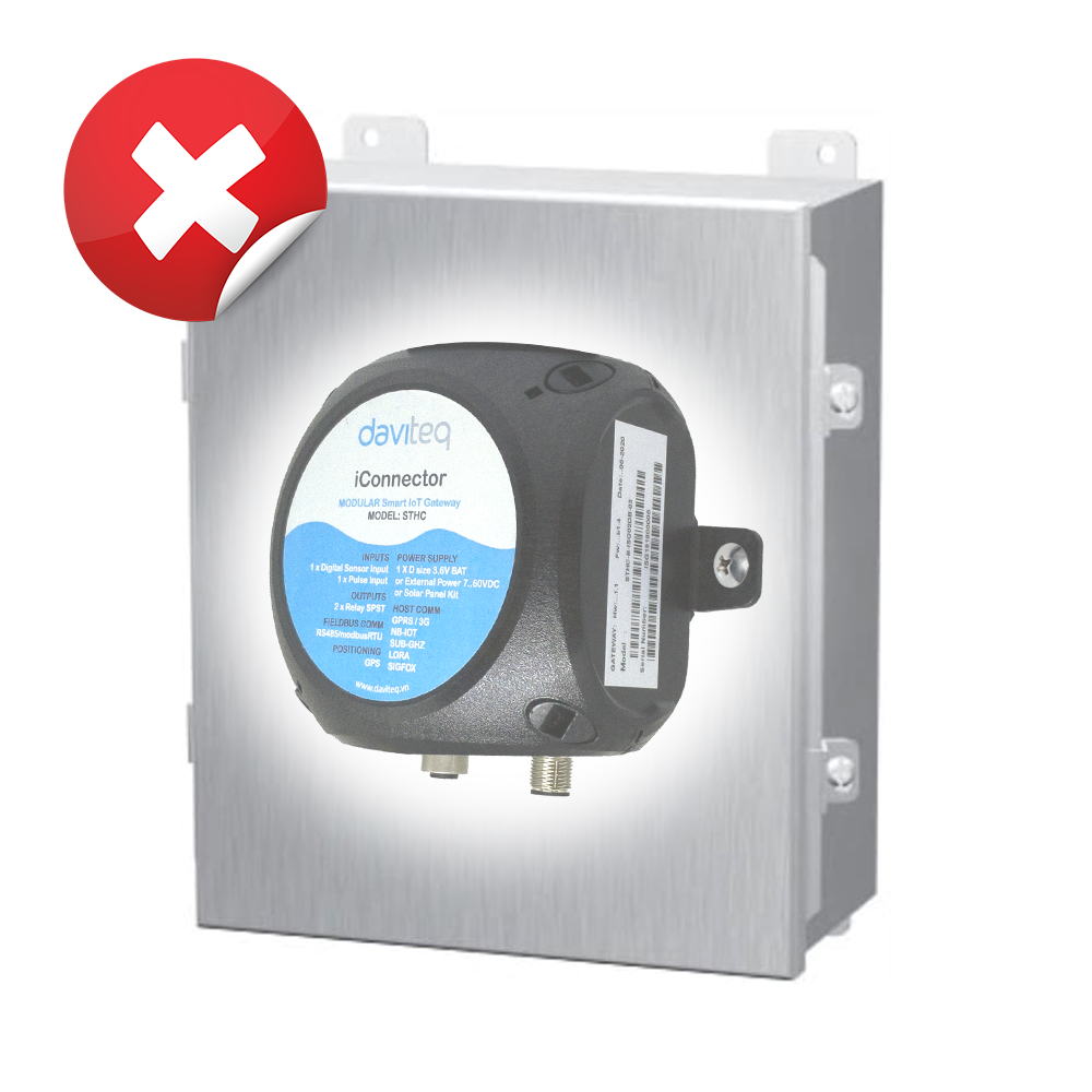
Installed on a wall or in non-metal box.
DO NOT install iConnector inside a complete metallic box or housing. The signal can not pass through metallic wall.
iConnector should be installed in a semi-metallic box.
Some non-metallic materials: plastic, glass, wood, leather, concrete, cement…
 |
 |
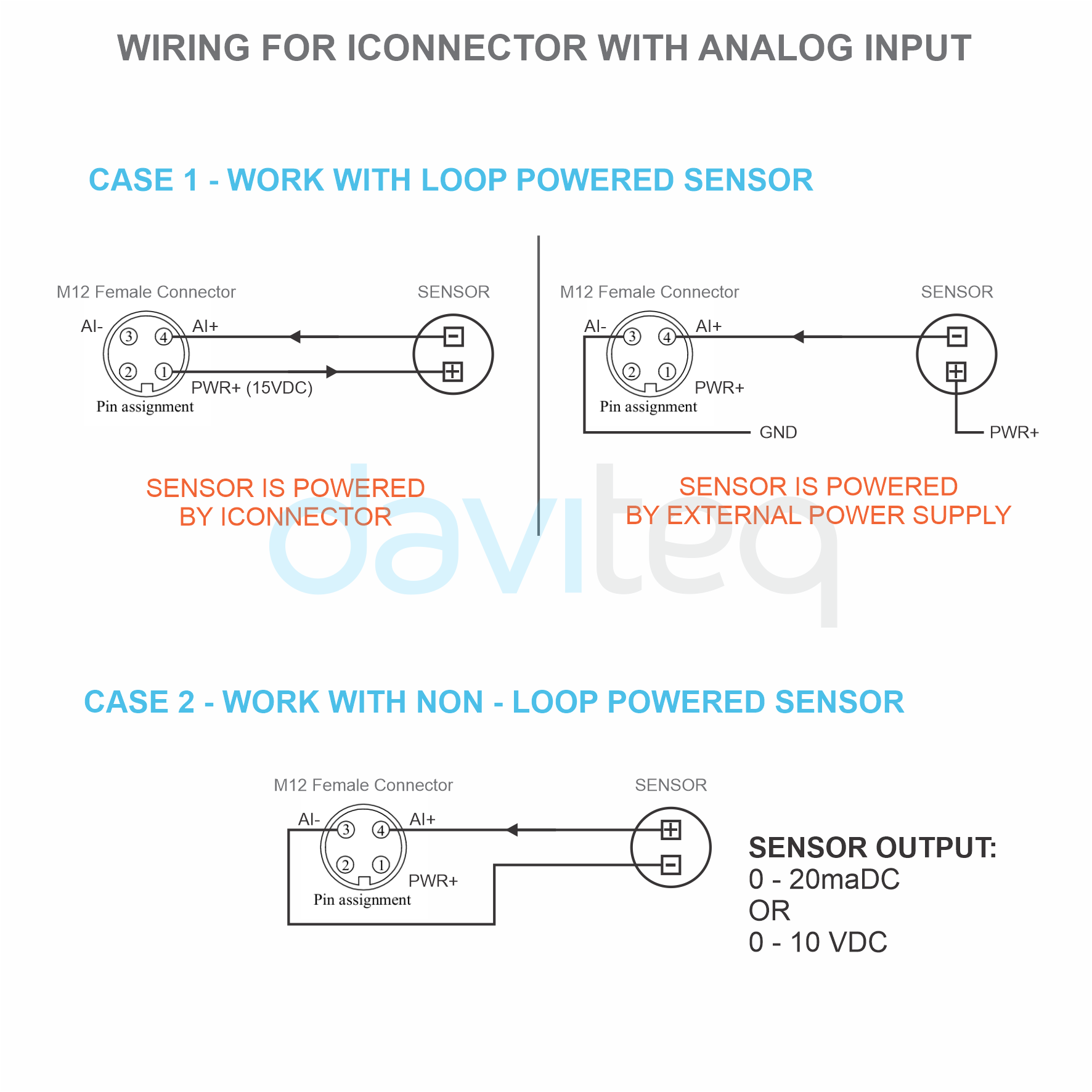
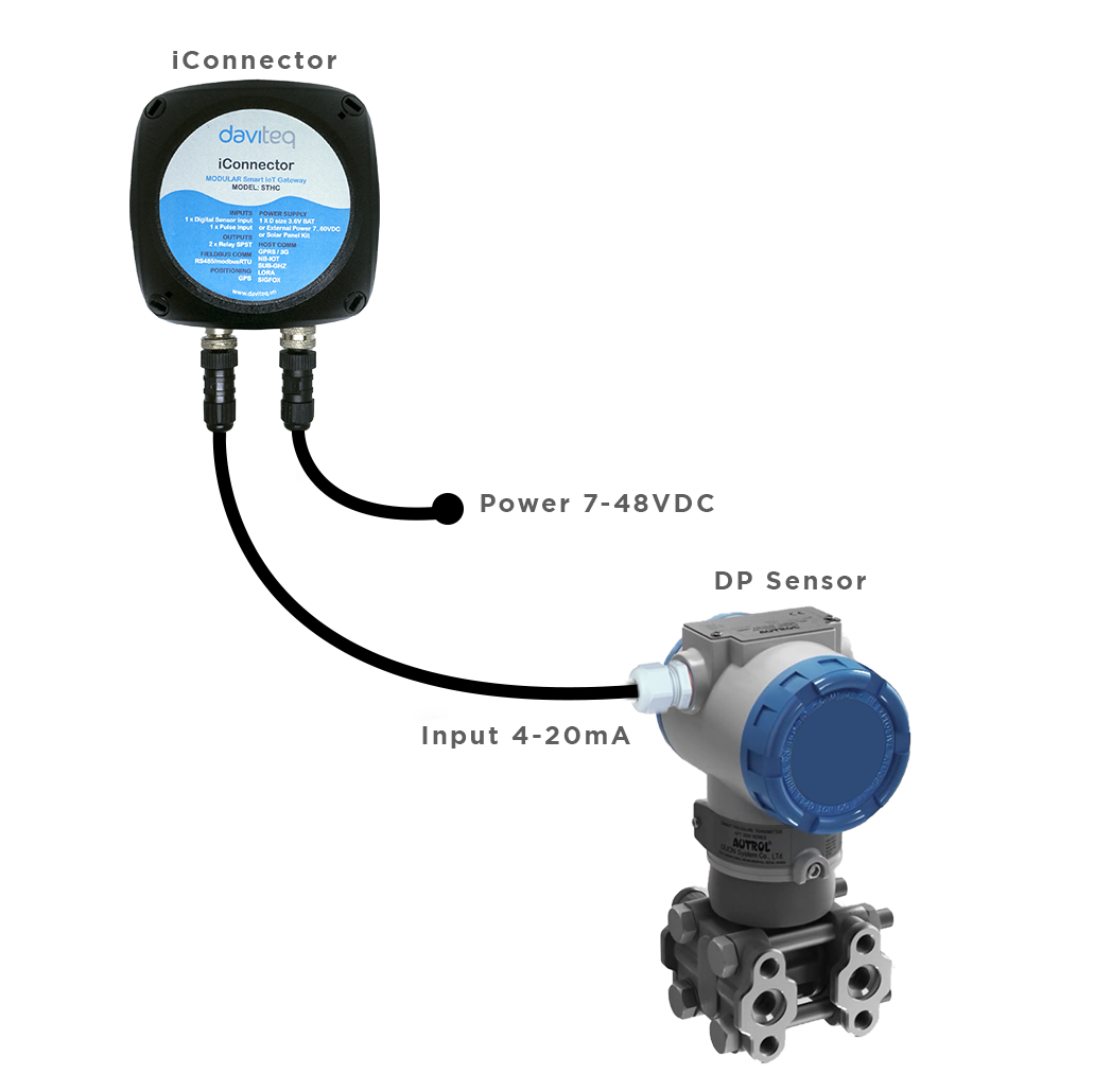
6.2 IO Wiring & Sensor installation
 |
 |
Install the sensor as shown below:
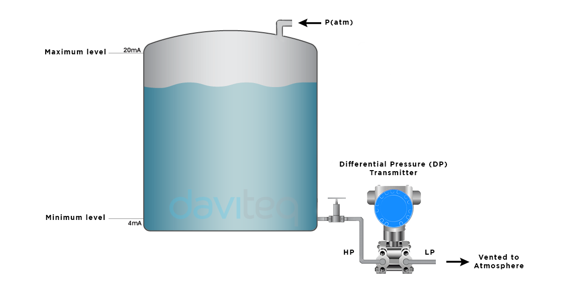
- Step 1: Open the back cover of the sensor
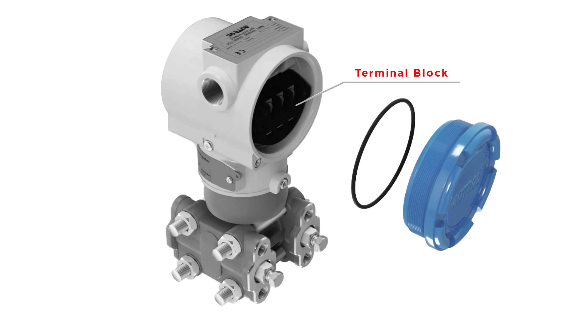
- Step 2:Wiring to sensors
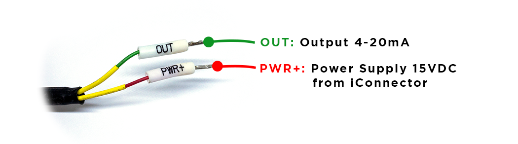
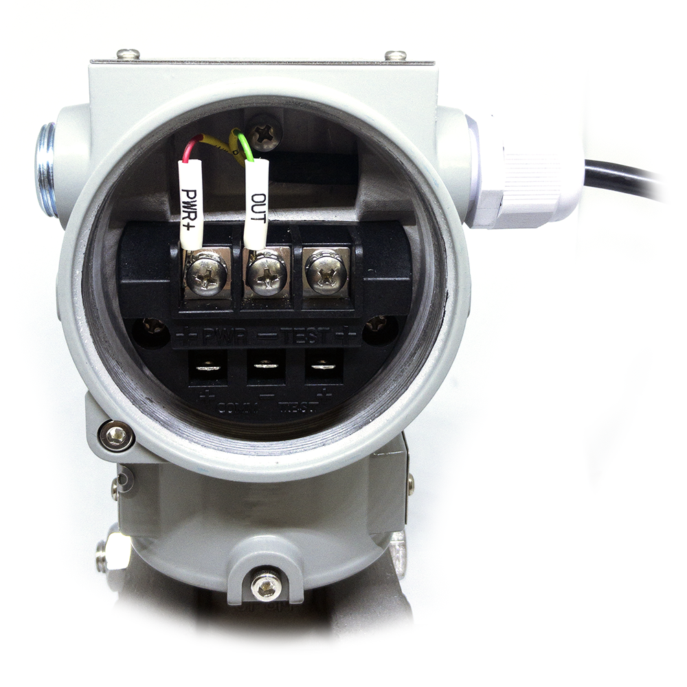
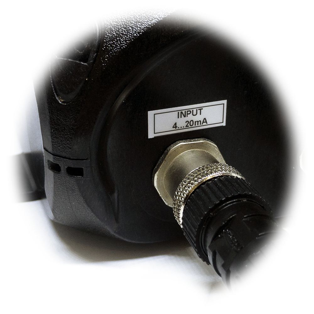
- Step 3: Connect Sensor to Input 4 .. 20mA port of iConnector via M12 connector
For more information about DP transmitter:
https://filerun.daviteq.com/wl/?id=lT9lfZuEQUQksWLhFgSoQrs28sEGY0Kt
6.3 Power Supply & Battery installation
6.3.1 Power Supply of iConnector
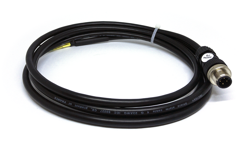
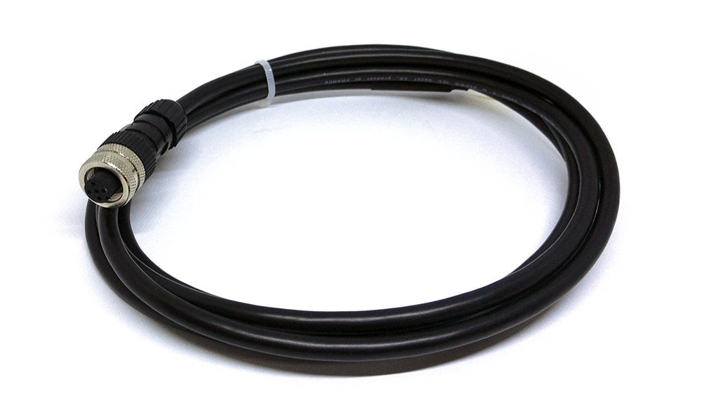
Connect 7 .. 48VDC power supply to iConnector via M12 Male connector
Use M12 female connection cable to connect to iConnector
6.3.2 Battery installation
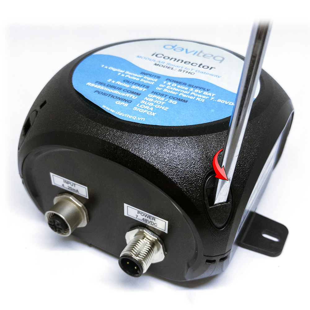
Steps for battery installation:
- Step 1: Using Flat Tip Screwdrivers to open the cover
- Step 2: Carefully pull out the top plastic housing
- Step 3: Insert the type D battery 3.6VDC, please take note the poles of battery
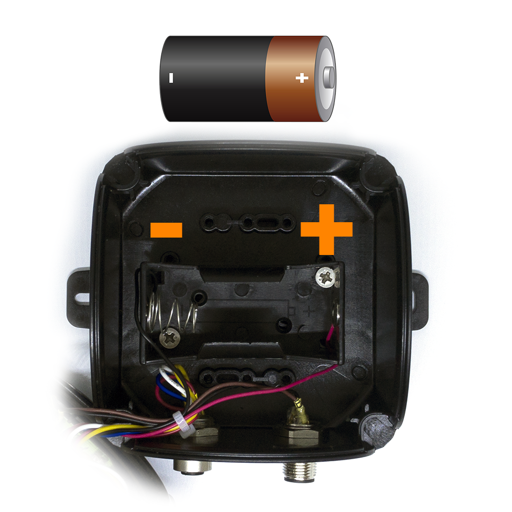
- Step 4: Insert the top plastic housing and locking by Flat Tip Screwdrivers
7. Troubleshooting
| No. | Phenomena | Reason | Solutions |
| 1 | The value of the sensor is 0 |
Sensor connecting 4-20mA is loose/not connected | Check sensor connection |
| 2 | The iConnector does not connected to the sever |
|
|
| 3 | The battery drains quickly | Turn On/Off tab configuration is incorrect | Check the configuration of the Turn On/Off tab |
No Comments