III. Globiots Configuration to read Slave Device Modbus Parameter
3.1 Configure Modbus Parameter on Globiots
Login Globiots with provided user and password
Click on Device, right-click, select Parameter
In List Parameters Page
• “Import Parameter”: click to Import Parameters from excel file. Excel file must have default structure.
• “Export Parameter”: click to export parameter to excel file.
• “Add parameter”: click to add a new parameter.
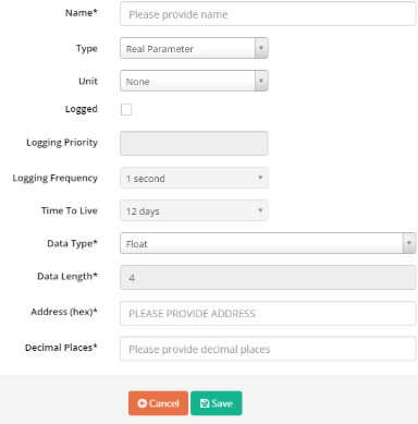
o Name: parameter name
o Type: Real Parameter or Virtual parameter
Real Parameter: Parameter from iConnector
Virtual Parameter: Parameter only in Server. Virtual parameter is create from formula of one or multi real parameter
If type is Virtual parameter, formula in Expression should be added
Mathematical Operators
|
Operator |
Description |
|
+ |
Additive operator / Unary plus |
|
- |
Subtraction operator / Unary minus |
|
* |
Multiplication operator, can be omitted in front of an open bracket |
|
/ |
Division operator |
|
% |
Remainder operator (Modulo) |
|
^ |
Power operator |
Boolean Operators
|
Operator |
Description |
|
= |
Equals |
|
== |
Equals |
|
!= |
Not equals |
|
<> |
Not equals |
|
< |
Less than |
|
<= |
Less than or equal to |
|
> |
Greater than |
|
>= |
Greater than or equal to |
|
&& |
Boolean and |
|
|| |
Boolean or |
Supported Functions
|
Function* |
Description |
|
NOT(expression) |
Boolean negation, 1 (means true) if the expression is not zero |
|
IF(condition,value_if_true,value_if_false) |
Returns one value if the condition evaluates to true or the other if it evaluates to false |
|
RANDOM() |
Produces a random number between 0 and 1 |
|
MIN(e1,e2, ...) |
Returns the smallest of the given expressions |
|
MAX(e1,e2, ...) |
Returns the biggest of the given expressions |
|
ABS(expression) |
Returns the absolute (non-negative) value of the expression |
|
ROUND(expression,precision) |
Rounds a value to a certain number of digits, uses the current rounding mode |
|
FLOOR(expression) |
Rounds the value down to the nearest integer |
|
CEILING(expression) |
Rounds the value up to the nearest integer |
|
LOG(expression) |
Returns the natural logarithm (base e) of an expression |
|
LOG10(expression) |
Returns the common logarithm (base 10) of an expression |
|
SQRT(expression) |
Returns the square root of an expression |
|
SIN(expression) |
Returns the trigonometric sine of an angle (in degrees) |
|
COS(expression) |
Returns the trigonometric cosine of an angle (in degrees) |
|
TAN(expression) |
Returns the trigonometric tangens of an angle (in degrees) |
|
COT(expression) |
Returns the trigonometric cotangens of an angle (in degrees) |
|
ASIN(expression) |
Returns the angle of asin (in degrees) |
|
ACOS(expression) |
Returns the angle of acos (in degrees) |
|
ATAN(expression) |
Returns the angle of atan (in degrees) |
|
ACOT(expression) |
Returns the angle of acot (in degrees) |
|
ATAN2(y,x) |
Returns the angle of atan2 (in degrees) |
|
SINH(expression) |
Returns the hyperbolic sine of a value |
|
COSH(expression) |
Returns the hyperbolic cosine of a value |
|
TANH(expression) |
Returns the hyperbolic tangens of a value |
|
COTH(expression) |
Returns the hyperbolic cotangens of a value |
|
SEC(expression) |
Returns the secant (in degrees) |
|
CSC(expression) |
Returns the cosecant (in degrees) |
|
SECH(expression) |
Returns the hyperbolic secant (in degrees) |
|
CSCH(expression) |
Returns the hyperbolic cosecant (in degrees) |
|
ASINH(expression) |
Returns the angle of hyperbolic sine (in degrees) |
|
ACOSH(expression) |
Returns the angle of hyperbolic cosine (in degrees) |
|
ATANH(expression) |
Returns the angle of hyperbolic tangens of a value |
|
RAD(expression) |
Converts an angle measured in degrees to an approximately equivalent angle measured in radians |
|
DEG(expression) |
Converts an angle measured in radians to an approximately equivalent angle measured in degrees |
Supported Constants
|
Constant |
Description |
|
e |
The value of e, exact to 70 digits |
|
PI |
The value of PI, exact to 100 digits |
|
TRUE |
The value one |
|
FALSE |
The value zero |
|
NULL |
The null value |
Note: Virtual parameter can't use for event.
Example 1: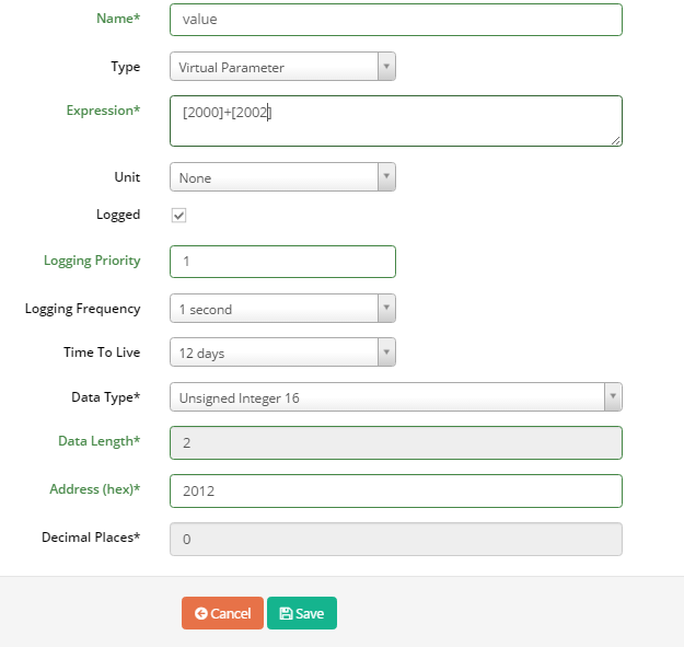 Value of Virtual Parameter have address at 2012 is calculated as follow [2012] = [2000] + [2002. ]In which address 2000 and 2002 are two real parameters
Example 2:
IF [2000]>10 then [2005]=1
IF [2000]<=10 then [2005]=2
Example 3:
IF [2000]=1 And [2005]=2 then [2010]=5
IF [2000]=!1 And [2005]=!2 then [2010]=[2007]+10
Example 4:
IF [2000]>10 then [200A]=1
IF [2000]<10 And [2010]=1 then [200A]=5
IF [2000]<10 And [2010]=!1 then [200A]=10
o Unit: Unit of parameter
o Logged: Tick to permit saving value of parameter into database
o Logging Priority: enter any value
o Logging Frequency: select frequency to log data from meter/sensor/device/instrument into iConnector memory
o Time to live: select how long data will be stored in database
o Data Type: Type of parameter
o Data Length: Length of data type, byte unit, display automatically with data type. If data type is String, data length should be input
o Address: Address in iConnector memory map to store value of parameter
o Decimal Places: number of decimal after the comma.
• Save: click to finish
• “Delete All”: click to delete selected parameters
• Edit: click to edit this parameter
• Delete: delete parameter
Note: After Configure Parameter, you must synchronize (refer to 5.11 Synchronize Device for more details)
3.2 Configure Modbus Command
- Select Device, right-click, select Modbus Command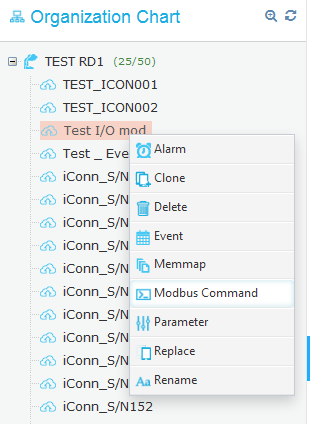
- Modbus Configuration page displays as below: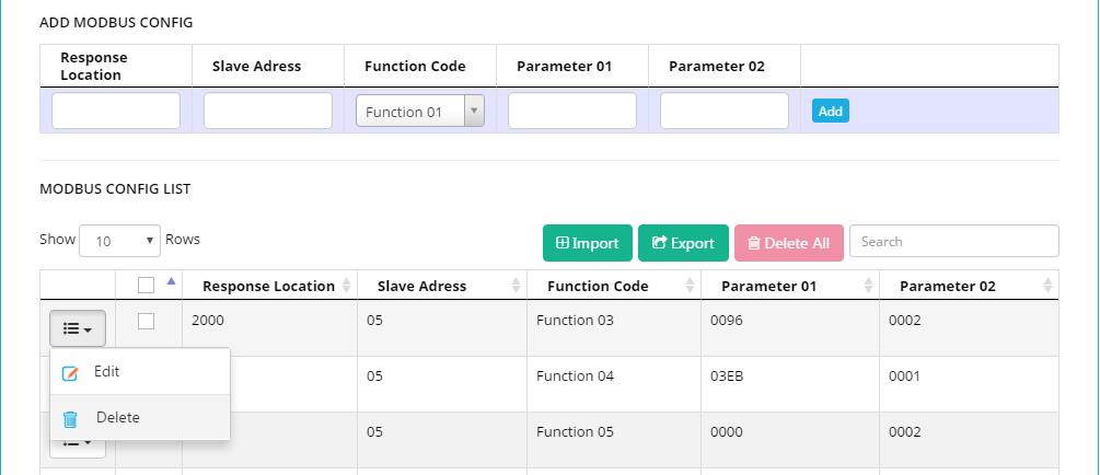
• MODBUS CONFIG LIST (1)
o Button “Edit”: click to edit Modbus Command. Modbus Command will display in (2) to edit
o Button “Delete”: click to delete Modbus Command.
o Button “Import”: click to import Modbus Command list from excel file
o Button “Export”: click to export Modbus Command list to excel file
o Button “Delete All”: click to delete all Modbus Command
• ADD MODBUS CONFIG (2)
o Response Location: Address of parameter in iConnector
o Slave ID: Modbus ID of meter/sensor/device/instrument which connect to iConnector through RS485 port
o Function Code: Function Code of Modbus Command. Function Code consist of read function and write function. In user manual of meter/sensor/device/instrument should mention supported function code.
o Parameter 01: Starting address of parameter in memory map of meter/sensor/device/instrument
o Parameter 02: Number of registers of parameter in memory map of meter/sensor/device/instrument
o Button “Add”: Click to add new Modbus Command
o Button “Update”: After click “Edit” button in (1), “update” will display. After editing Modbus command and click “Update” to save change.
Note:
Response Location in iConnector for read Modbus data :0x2000 -> 0x21FF
Response Location in iConnector for write Modbus data: 0x3000 -> 0x307F
After configuring, Modbus Command should be synchronized to iConnector (refer to 5.11 Synchronize Device for more details)
Example:
Configure modbus command for reading parameter Voltage, data type: float, from address 0000 on power meter (ID=32) and store at address 2000 (hex) on iConnector, using function 04 of modbus command. The configuration as follow:
Response Location = 2000
Slave address = ID=32 (decimal) =20 (Hexa)
Parameter 01 = Start Address = 0000
Parameter 02 = Number of register of parameter. Data type = float (4 bytes) = 02 register
3.3 Synchronize Modbus Parameter configurations and Modbus Command configurations to iConnector
Right click Device name, select Sync, and tick all type of configuration to synchronize to iConnector, click Sync, enter password to confirm permission
After successful synchronization, Text Synchronized should appear on 4 line of dialog box. If iConnector disconnected, message should appear to inform that synchronization will implement once iConnector connect to server.
No Comments