USER GUIDE FOR ICONNECTOR 3G INTEGRATED WIRELESS CO-ORDINATOR STHC-ISG02DB-WS433-CL-04
| STHC-ISG02DB-WS433-CL-04-MN-EN-01 |
FEB-2020 |
This document is applied for the following products
| SKU |
STHC-ISG02DB | HW Ver. | 3.3 | FW Ver. | 3.4 |
| WS433-CL-04 | HW Ver. | 2.3 | FW Ver. | 1.9.3 | |
| Item Code |
STHC-ISG02DB-WS433-CL-04 | iConnector 3G Dual Band*, internal GSM antenna, integrated wireless co-ordinator with 0 dbi external antenna, M12 male connector, RS485 ModbusRTU | |||
1. Functions Change Log
| HW Ver. | FW Ver. | Release Date | Functions Change | |
| Gateway | 3.3 |
3.4
|
NOV-2019 |
|
| Co-odinator | 2.3 | 1.9.3 | NOV-2019 |
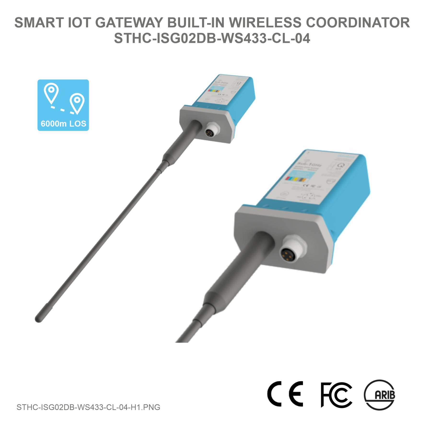
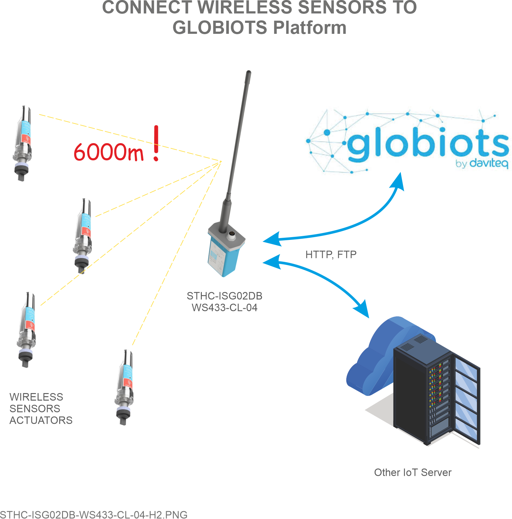
2. Introduction
STHC is a Smart IoT Gateway, aka iConnector, a main component in any IoT application. iConnector has a role to connect the real World's things like sensors, meters, ,machines...to server system for data logging, data analytics, monitoring & controls... This iConnector is build-in a wireless co-ordinator in a wireless sensor network, a high-performance type to facilitate remote configuration and diagnostics, as well as remote monitoring and control via any IIoT platform. It is able to configure the parameters for all end nodes in the network. By the Sub-Ghz technology from Texas Instruments, it is easy to establish multiple networks in same area without interference or channel conflict. One co-ordinator can handle maximum of 40 end nodes in its network. LOS transmission distance up to 6000m. The installation and configuration is very simple. Setting up a wireless sensor network has never been this easy.
3. Specification
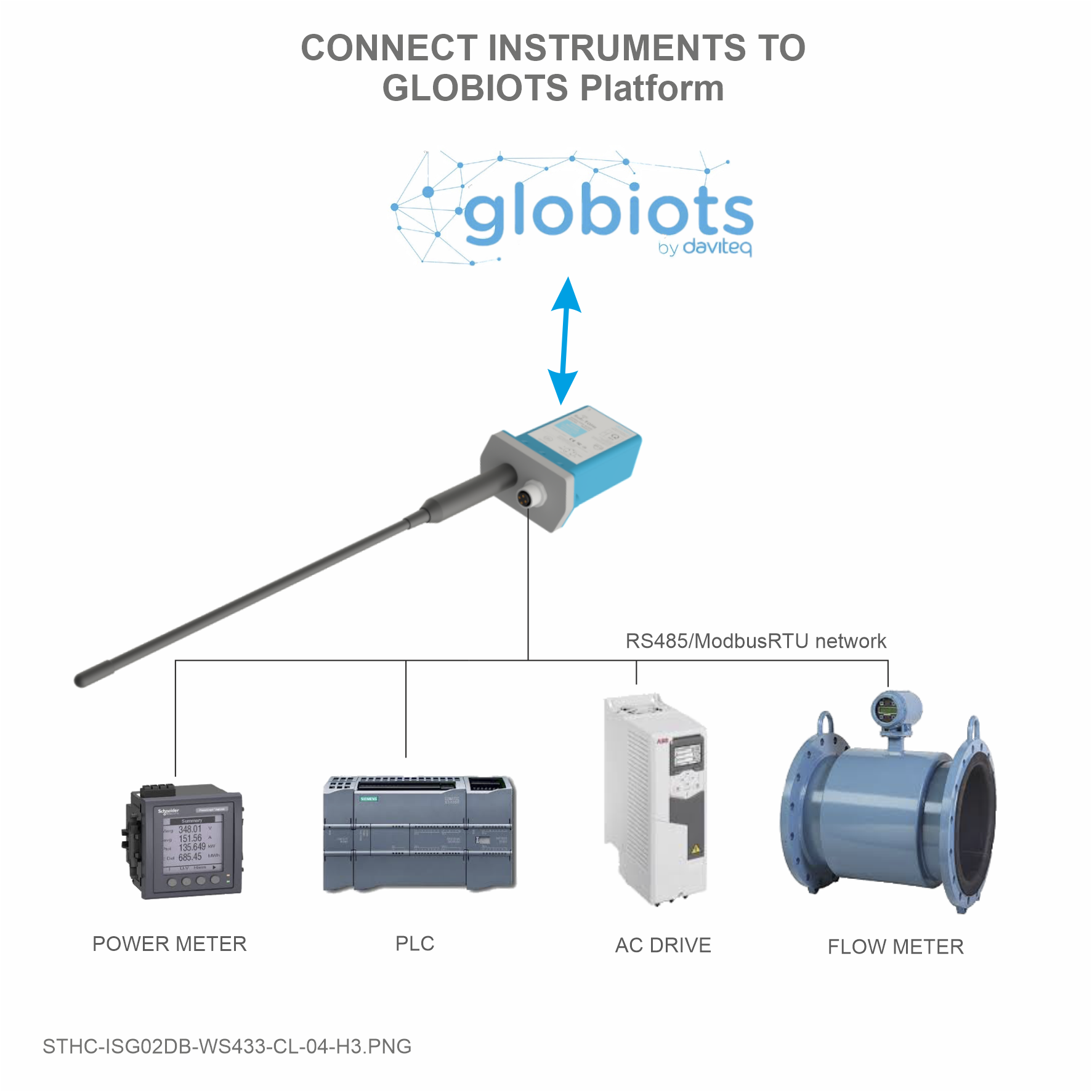
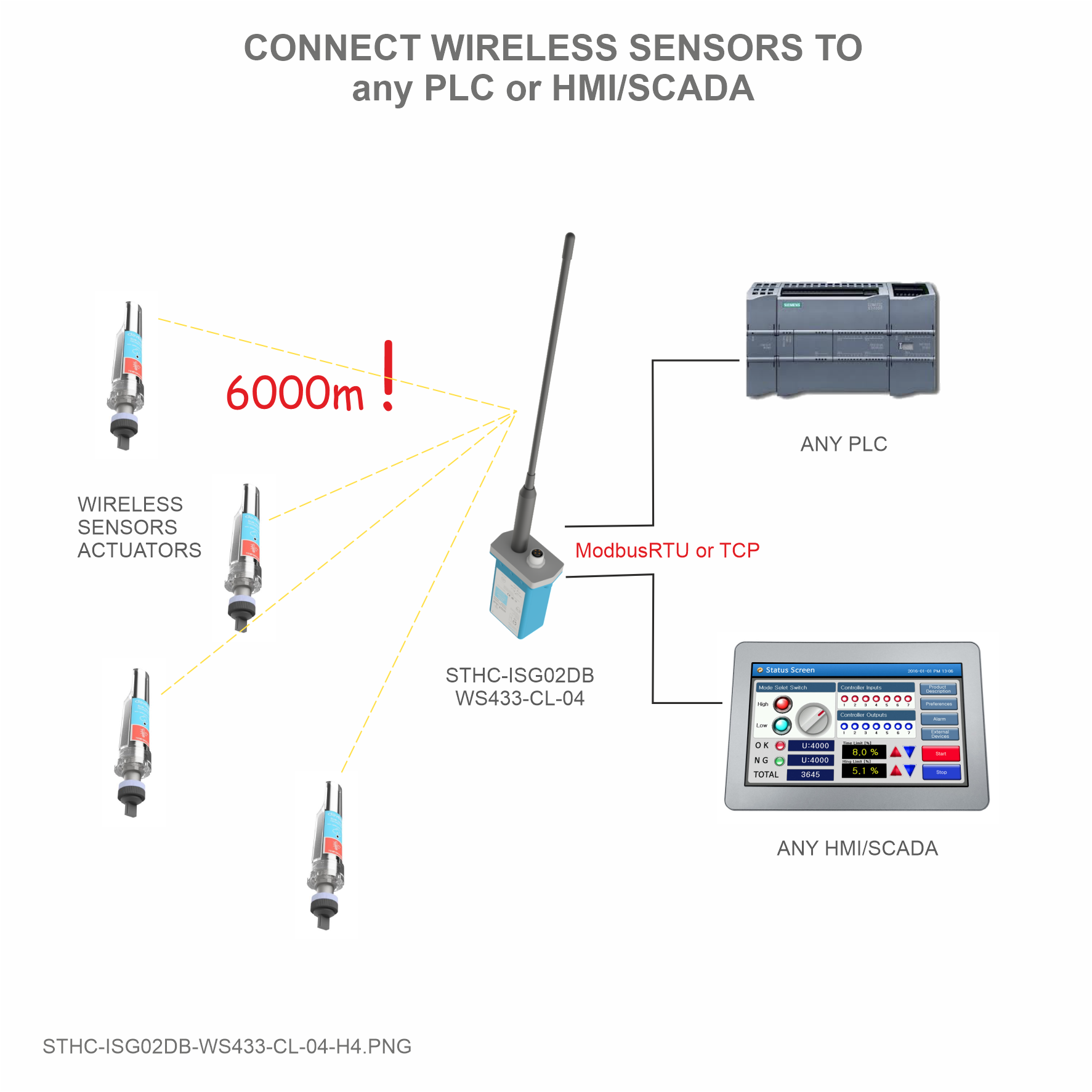
| Host Communication Cellular type | Dual band (2100/900)/3G, internal GSM antenna, integrated wireless co-ordinator |
| Fieldbus communcation | ModbusRTU x 01 port |
| Data speed | Up to 50kbps |
| Tranmission distance | LOS 6000m @ 50 kpbs (antenna height is 4m minimum) |
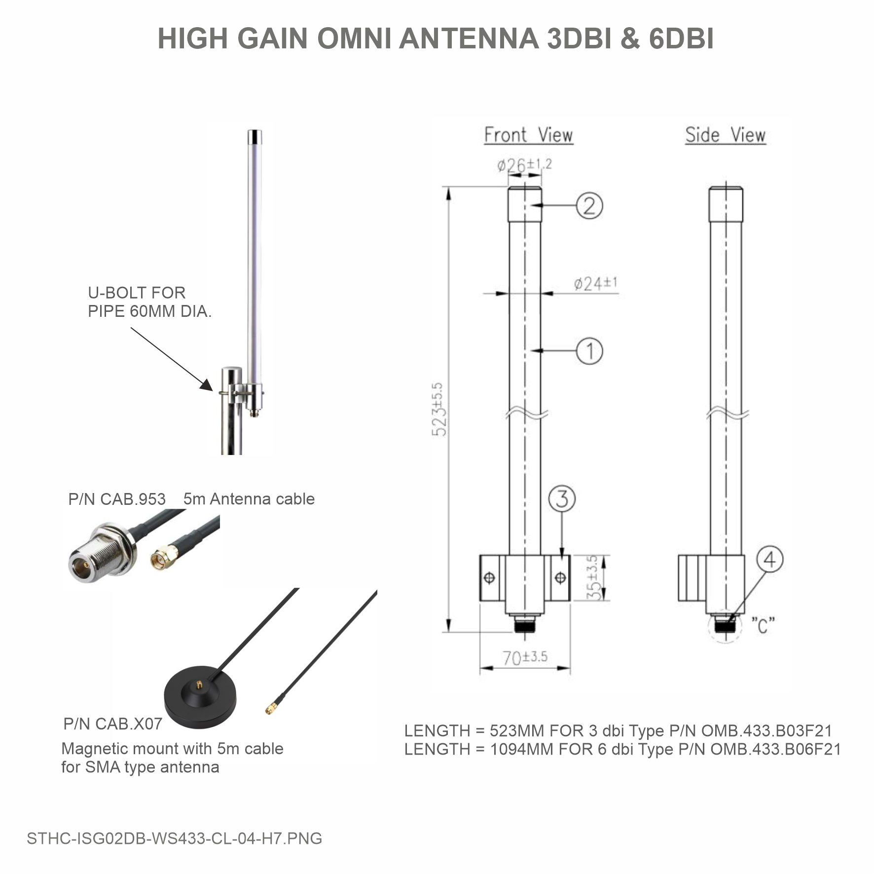
| Antenna | Standard external antenna 0 dbi, option 3dbi, 6dbi, 9dbi |
| Power supply | 7..48VDC, avg 200mA, peak 1.5A |
| On-board memory & sensors | 2MB Flash, PCB temperature sensor |
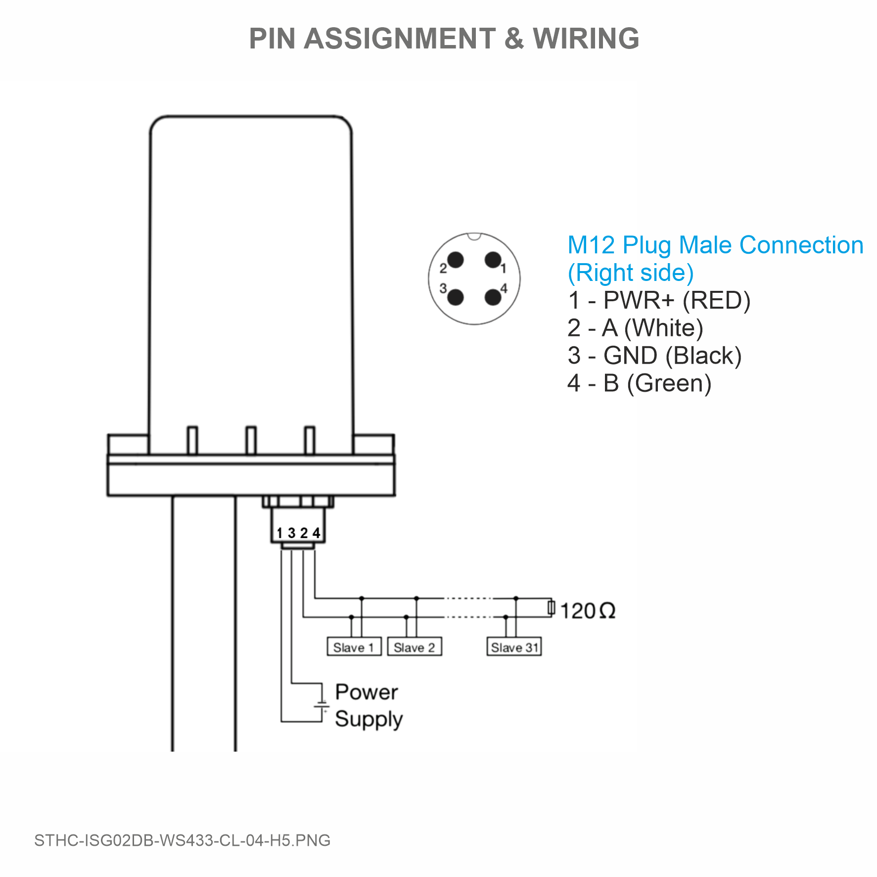
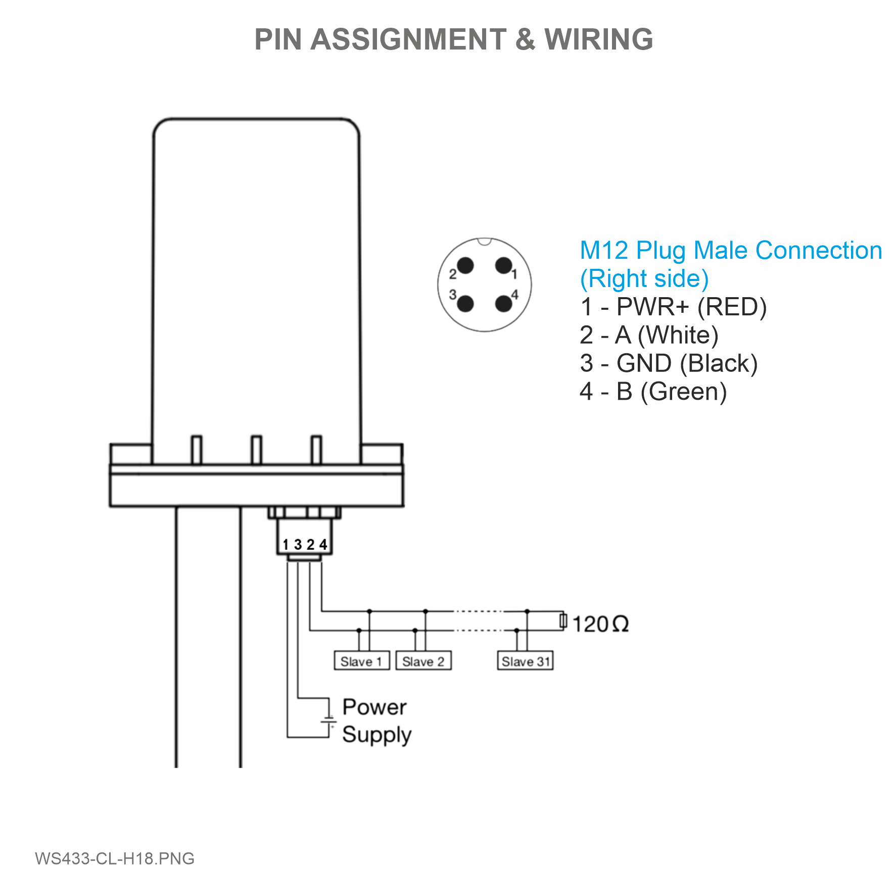
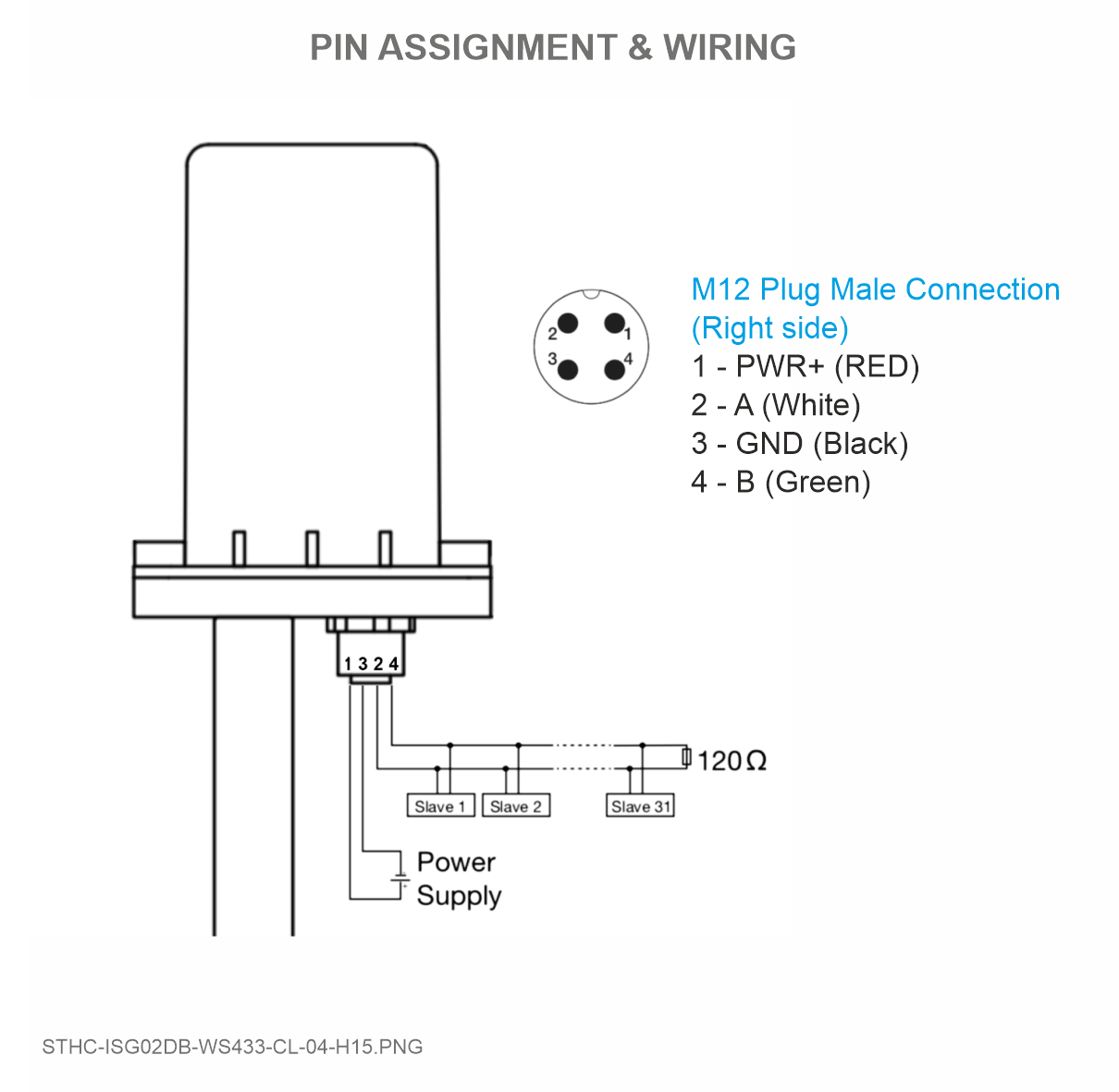
| Electrical connector | M12-female, 4-pin A-coding |
| Buzzer | Internal buzzer |
| Back-up battery | Lithium Super Capacitor |
| RF frequency band | Free license ISM 433.92Mhz (for others 868, 915, 920Mhz, refer related datasheets) |
| Ready to comply | ETSI EN 300 220, EN 303 204 (Europe) FCC CFR47 Part15 (US), ARIB STD-T108 (Japan)** |
| Vietnam Type Approval Certification | QCVN 73:2013/BTTTT, QCVN 96:2015/BTTTT (DAVITEQ B00122019) |
| Security Standard | AES-128 |
| Operating temperature | -40oC..+85oC |
| SIM slot | 01 x micro-SIM |
| Housing | Aluminum + Polycarbonate, IP67 |
| Included accessories | Mounting bracket for wall mount |
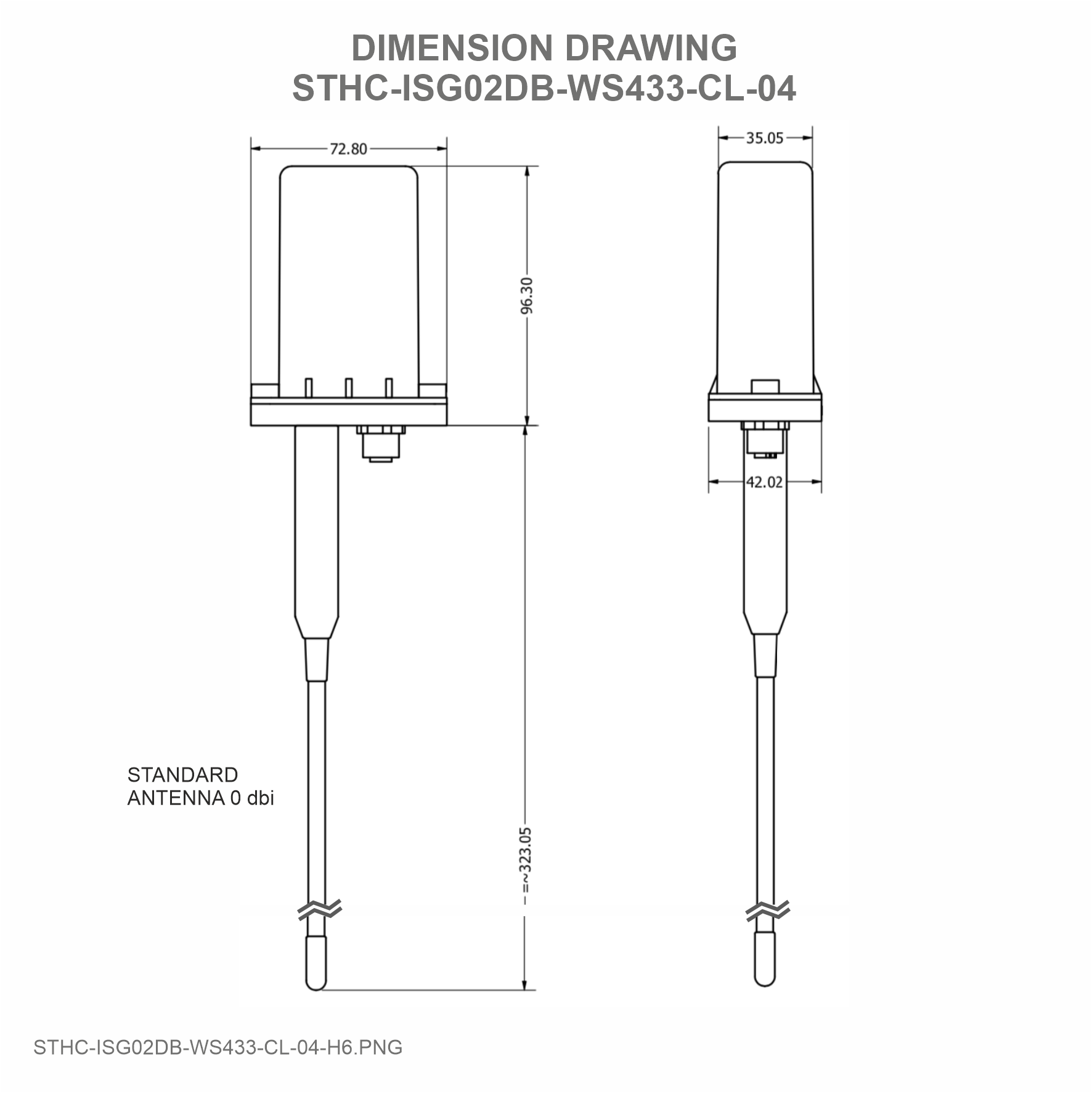
| Product dimension | H106 x W73x D42 mm (excluded antenna) |
| Net weight | 190 grams |
| Box dimension | W160 x D150 x H100 mm |
| Gross weight | < 300g |
4. Product Pictures
|
 |
 |
 |
 |
 |
 |
 |
5. Operation Principle
After the power supply will have 5 minutes to add nodes (value enb_auto_add_sensors = 1 in 5 minutes then = 0), push button function and hall sensor are only available in the first 5 minutes
- Press and hold the push button or bring the magnet near the Hall sensor for 2s => see the LED blink once or the buzzer will ring 1 Beep => release the push button or take the magnet to set Data rate RF 50kbps
- Press and hold the push button or bring the magnet near the Hall sensor for 5s => see the LED blink twice or the buzzer beep 2 Beep => release the push button or take the magnet to set Data rate RF 625bps
- Press and hold the push button or bring the magnet near the Hall sensor for 10s => see the LED blinking 3 times or the buzzer buzzes 3 Beep => release the push button or take the magnet to perform the User factory reset (User factory reset = reset frequency number, RF transmit power, data rate, Node ID of 40 WS, Modbus operating parameters, compare time for data status)
- If it takes more than 30 seconds, the button will be deactivated
5.1 Add Sensor Node
Add Sensor Node ID automatically
 |
|
-
Step 1: After supplying power the iConnector via M12 connector, the Node ID must be registered within the first 5 minutes, up to 40 WS.
Step 2: Bring the wireless sensor closer to the iConnector's antenna then take off the wireless sensor battery, wait for 5s then insert the battery again. If:
- Buzzer plays 1 peep sound, LED blink 1 time, that means registering Node ID on iConnector successfully.
- Buzzer plays 2 peep sounds, LED blink 2 times, that this Node ID is already registered.
If you do not hear the "Peep" sound, please disconnect the power the iConnector, wait a few minute and try again.
Node id added in this way will be written to the smallest node_id_n address which is = 0.
Set Rssi_threshold (see RF MODE CONFIG (in the Modbus Memmap of WS433-CL), default -25): The case if Co-ordinator is on high position and need to add node sensor. We set the sensor as close as possible and set the Rssi_threshold to -80, -90 or -100 to increase the sensitivity to allow iConnector can add sensors at a longer distance. After that, perform 2 steps of adding sensors and then reset Rssi_threshold = -25.
Enb_auto_add_sensors configuration (see RF MODE CONFIG (in the Modbus Memmap of WS433-CL)): In case you do not want to turn off the power iConnector, you can set Enb_auto_add_sensors = 1, this way we have 5 minutes to add nodes (add up to 40 nodes) . After 5 minutes Enb_auto_add_sensors will automatically = 0.
Configuration
- Protocol: Modbus RTU
- Address: 1 - 247
- Baud rate: 9600 , 19200
- Parity: none, even, odd
- Stop bits: 1
Memmap resgisters
You can download Modbus Memmap of WS433-CL-FW_V2.0 with the following link:
https://filerun.daviteq.com/wl/?id=BKEaUzdArkoc0Hc7nfpRShdPVToVrqQZ
5.2 Check after configuring the iConnector
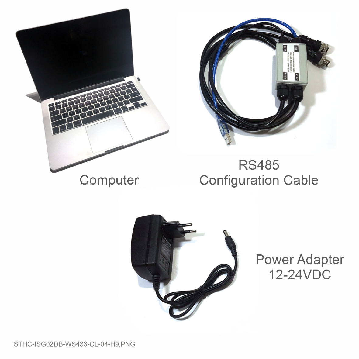
First, you need to prepare
Step 1: Open Modbus tool on PC
- You can download Daviteq Modbus Configuration Tool Version 1.4 with the following link:
https://filerun.daviteq.com/wl/?id=qK0PGNbY1g1fuxTqbFW9SXtEvCw7bpc6
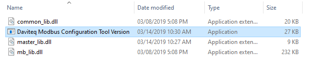
- Unzip TOOLS-SW-EN-02.zip and run file application "Daviteq Modbus Configuration Tool Version"
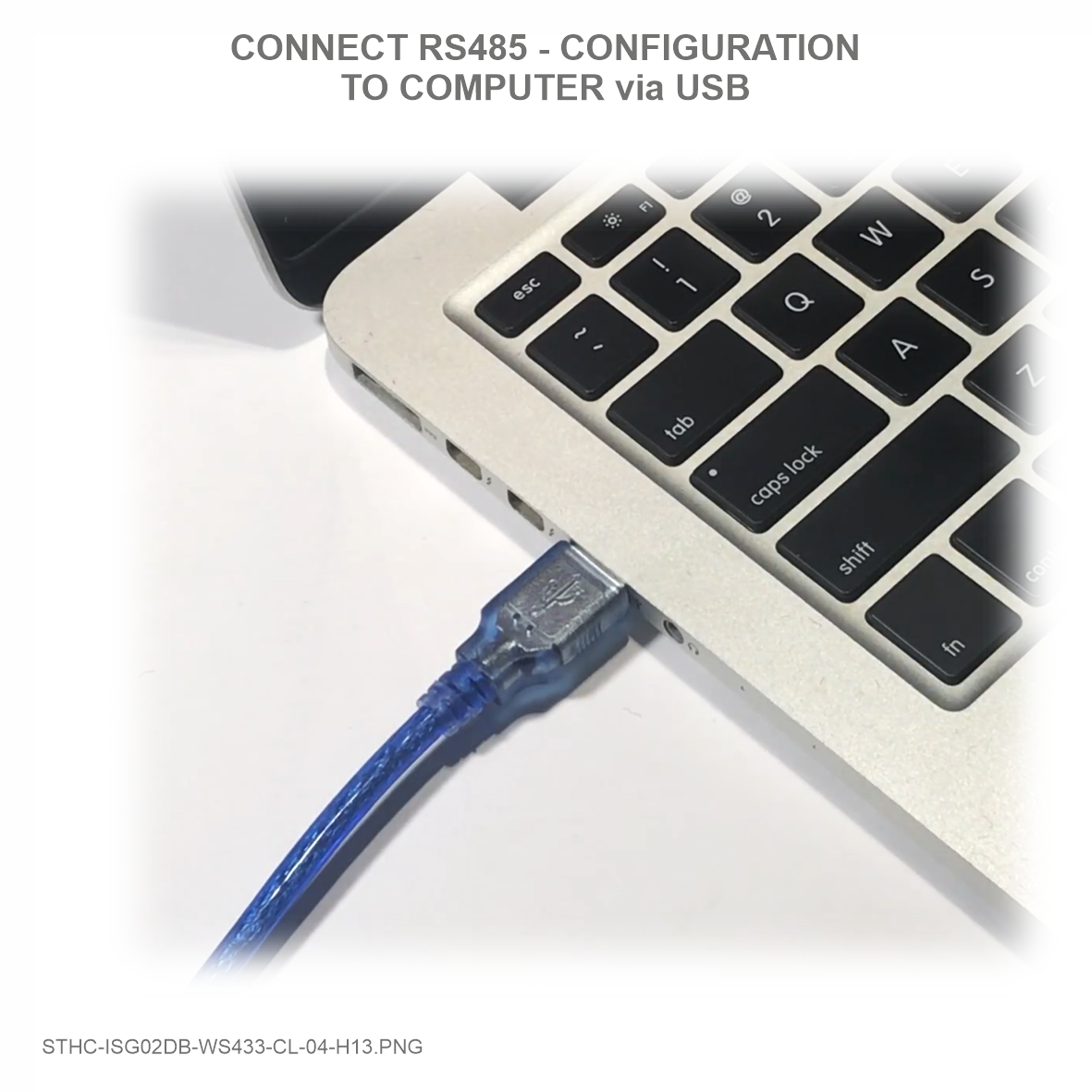
- Choose COM Port (the Port which is USB cable plugged in)
- Set the BaudRate: 9600, Parity: none
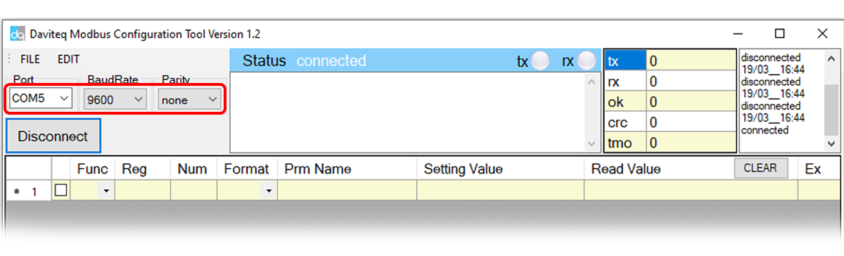
- Click “ Connect “ untill the Status displays “disconnected” to “connected“. It means the WS433-CL-04 is being connected with computer;
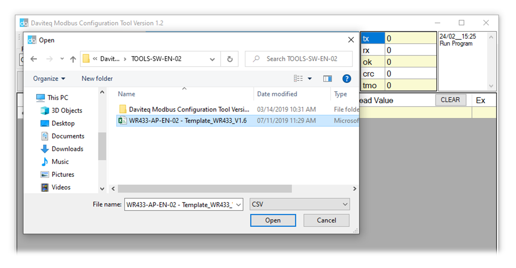
- Next, we need to import the configuration file for WS433-CL-04 by importing the csv file: Go to MENU: FILE / Import New / => select the file with name Template_WR433_V1.6.csv. This file is attached in the zip file.
Step 2: Check information of sensor after adding S/N of each sensor
5.3 SIM configuration
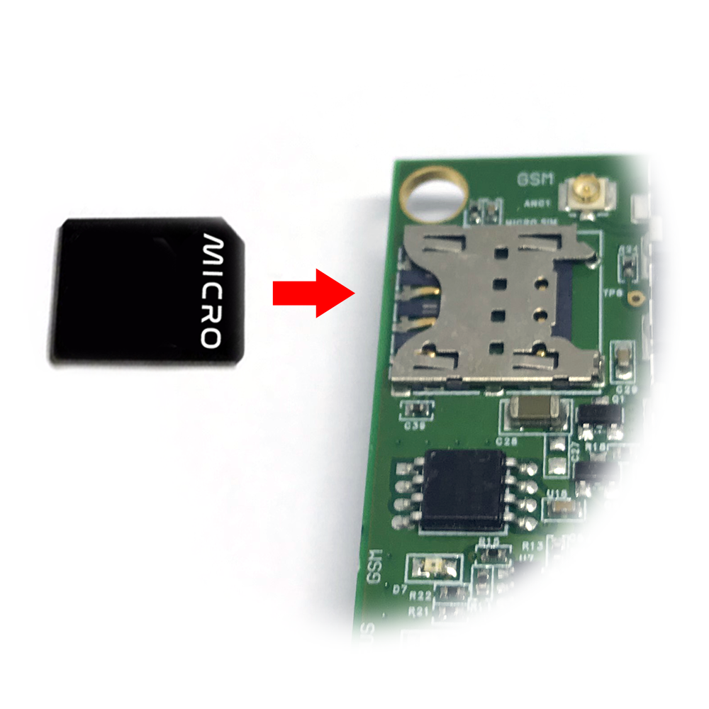
iConnector 3G uses micro-SIM and needs to be configured to use the data network
- Open iConnector cover and install the SIM card

- Based on the information of the mobile carrier that provides the SIM card, we configure data such as APN, username, password on the 2G/3G tab

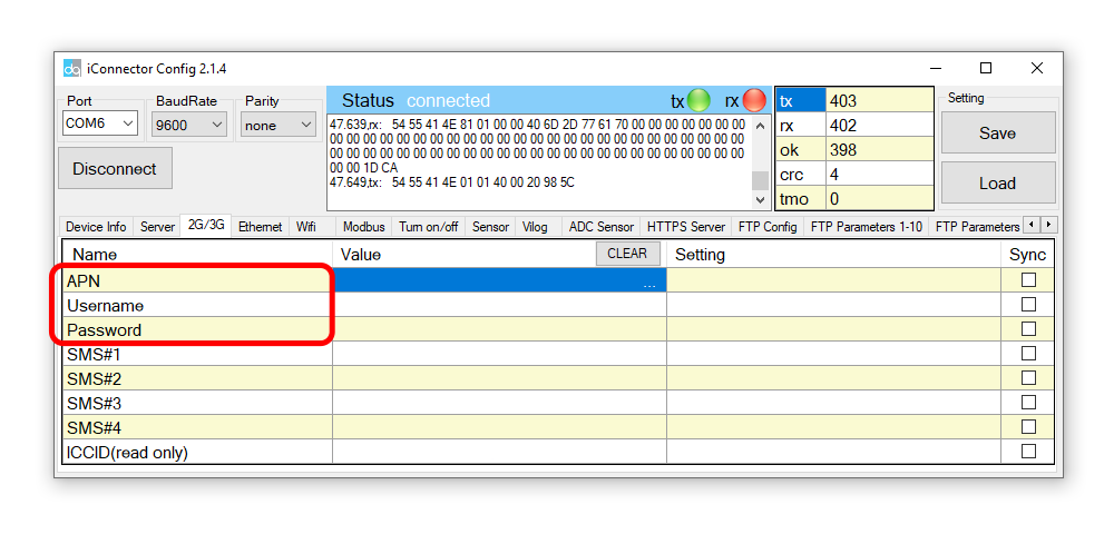
How to use iConnector config tool (Click Here)
5.4 Reset sensor and iConnector sensor node
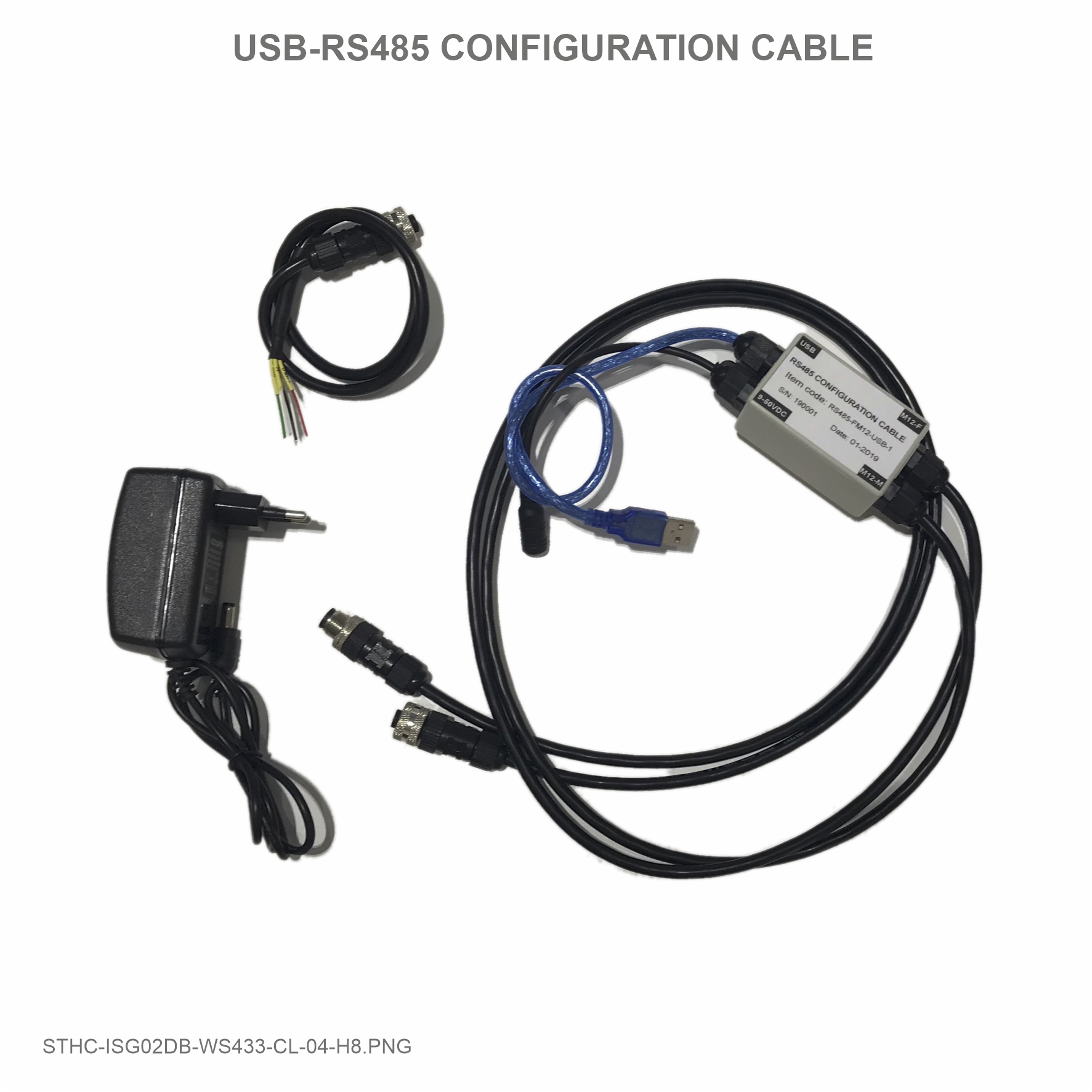
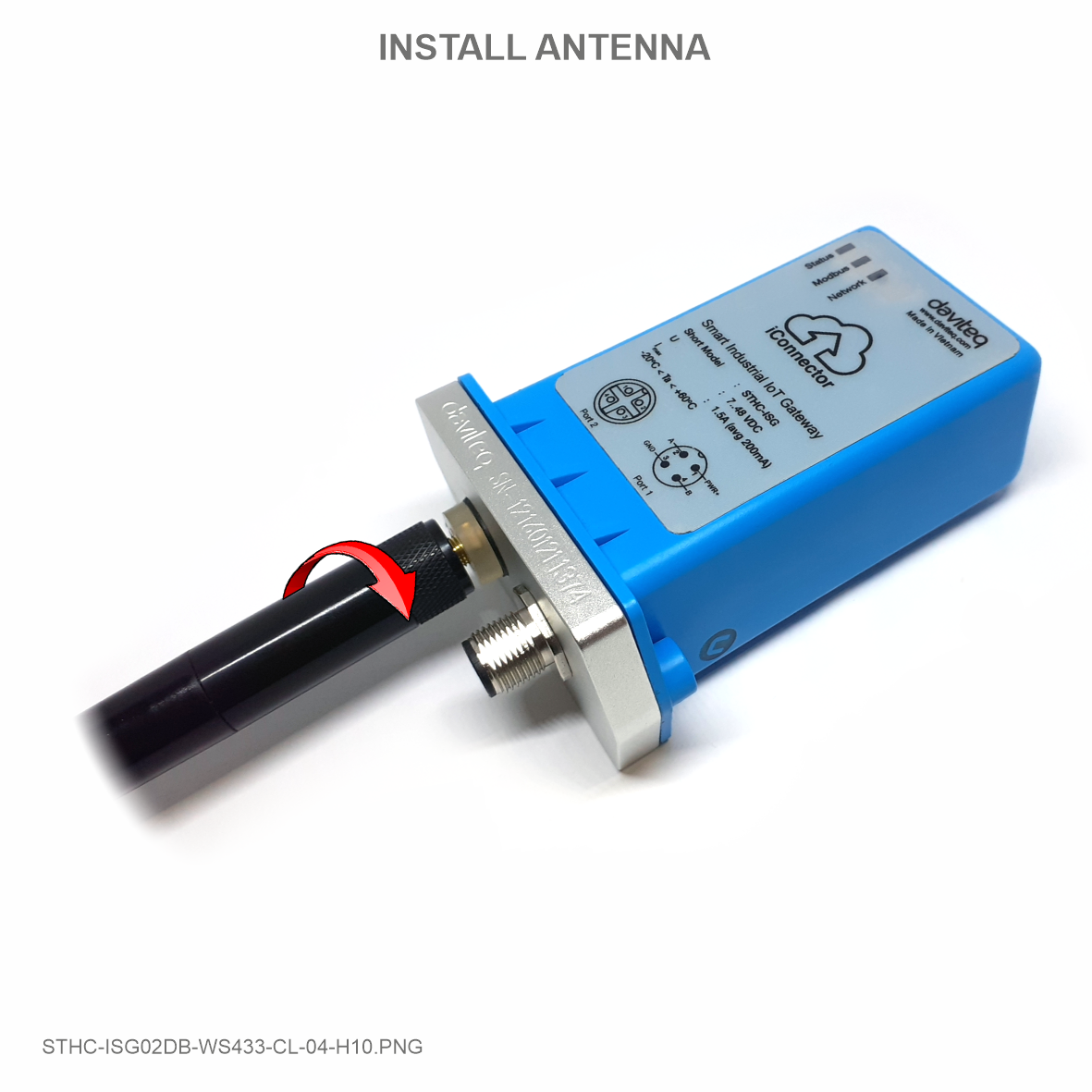
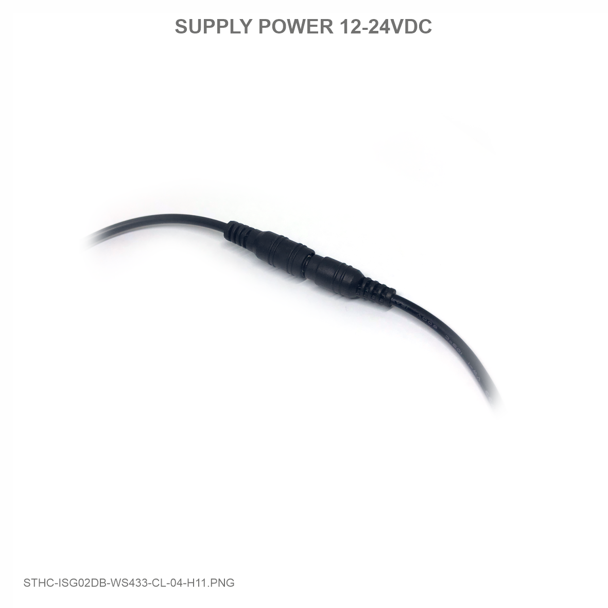
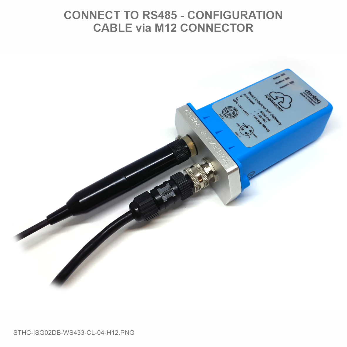
Step 1: Connect Antenna, RS485 - configuration cable and power supply co-ordinator
|
 |
 |
 |
Step 2: Put the magnet closer to the icon on iConnector until you hear "peep" 3 times to reset (2 times for 625 kps option)
Step 3: Take off the sensor cover and press the button until you see LED flashes 3 times to reset (2 times for 625 kps option)
6. Installation
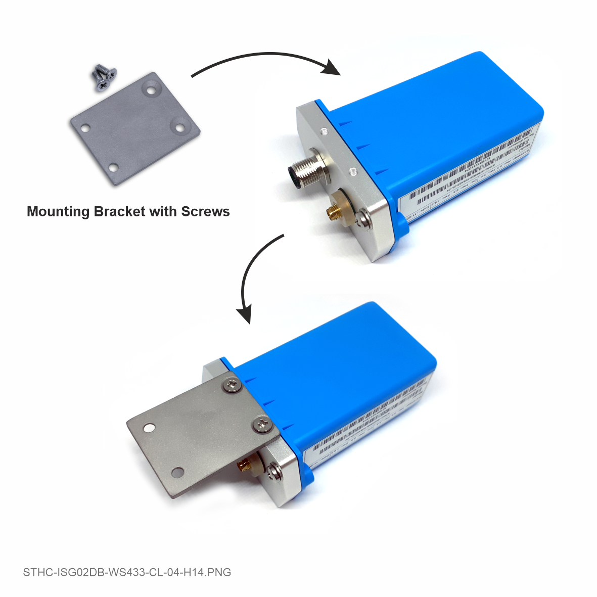
6.1 Mounting bracket installation
The mounting bracket is made from hard metallic material. Following to these steps as the below picture
6.2 Installation location
To maximize the distance of transmission, the ideal condition is Line-of-sight (LOS) between the two modules. In real life, there is no LOS condition. However, the two modules still communicate each other, but the distance will be reduced significantly.
Therefore, to maximize the transmission distance, please pay attention to the following conditions:
- DO NOT install the wireless module inside a complete metallic box or housing. The signal can not pass through metallic wall;
- This wireless module would be installed a semi-metallic box, because the RF signal can pass through the non-metal wall/are;
- The best case is to install the wireless module inside or Non-metallic box;
Some non-metallic materials: plastic, glass, wood, leather, concrete, cement…
6.3 IO Wiring & Sensor installation
 |
|
|
|
7. Troubleshooting
| No. | Phenomena | Reason | Solutions |
| 1 | Cannot read modbus |
|
|
| 2 | Failed to add auto sensor |
|
|
| 3 | Read modbus normal health values but read the data of the node, all are 0 |
|
|
| 4 | The node's data has no data of prm1 and prm2 |
|
|
| 5 | Status led of iConnector doesn’t light |
|
|
| 6 | Mobus led of iConnector doesn’t light |
|
|
| 7 | Network led of iConnector doesn’t light |
|
|
8. Support contacts
|
Manufacturer
Daviteq Technologies Inc Email: info@daviteq.com | www.daviteq.com
|
Distributor in Australia and New Zealand
Templogger Pty Ltd Tel: 1800 LOGGER Email: contact@templogger.net |

No Comments