USER GUIDE FOR ICONNECTOR CELLULAR CAT M1, NB1, 2G, GLOBAL BAND STHC-ISGM1-NB1-2G-NC
| STHC-ISGM1-NB1-2G-01-MN-EN-01 |
SEP-2020 |
This document is applied for the following products
| SKU | STHC | HW Ver. | 3.3 | FW Ver. | IoT_N1.0 |
| Item Code |
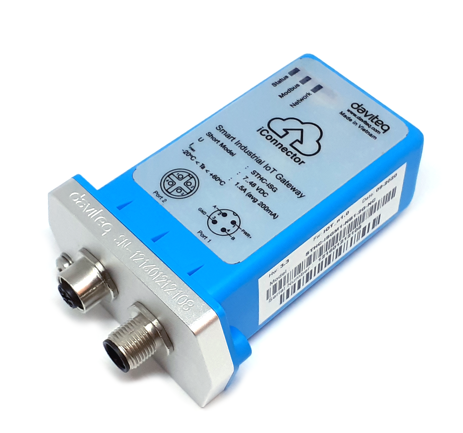
STHC-ISGM1-NB1-2G-NC |
iConnector CAT M1, NB1, 2G, Global Band, internal antenna, with 02 relays |
|||
1. Functions Change Log
| HW Ver. | FW Ver. | Release Date | Functions Change |
| 3.3 | IoT_N1.0 | SEP-2020 |
2. Introduction
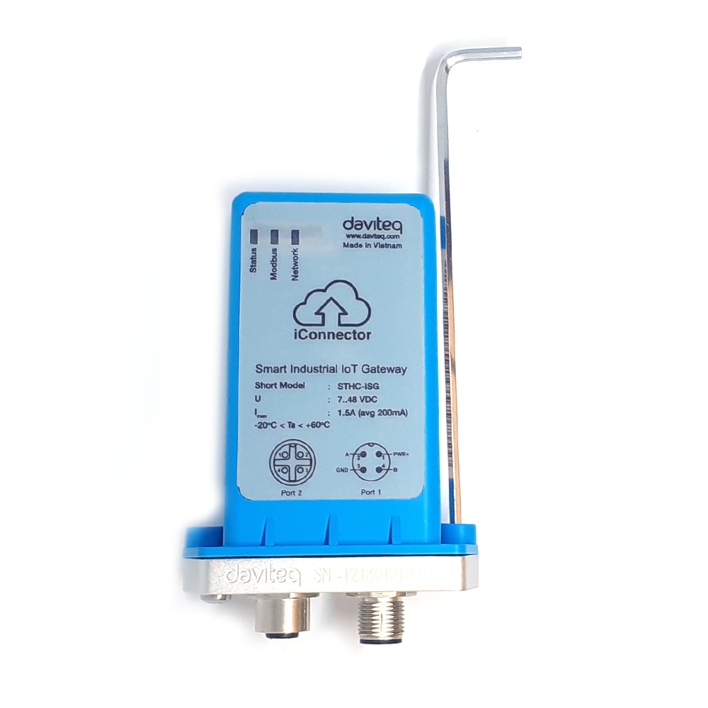
STHC is a Smart IoT Gateway, aka iConnector, a main component in any IoT application. iConnector has a role to connect the real World's things like sensors, meters, ,machines...to server system for data logging, data analytics, monitoring & controls...iConnector support multiple Industrial Fieldbus like Modbus, EthernetIP, Profinet, CClink, Wireless sensor network...It connects to server system via LAN/WAN as Ethernet, WiFi or Cellular.
3. Specification
| Host Communication | CAT M1, NB1, 2G, Global Band, internal antenna |
| Host communication supports | TCP/IP, UDP/IP, FTP, HTTPS, SNMP... |
| Fieldbus communcation | ModbusRTU x 01 port, 31 slaves, max 19.2 kpbs |
| Vietnam Type Approval Cerification | QCVN 54:2011/BTTTT, QCVN 15:2015/BTTTT (DAVITEQ B00122019) |
| Optional | Integrated wireless co-ordinator with external antenna or internal antenna |
| Optional | Internal buzzer (to replace Relay 1) |
| Power supply | 7..48VDC, avg 200mA, peak 1.5A |
| Battery | Lithium Battery 3.7VDC |
| On-board memory & sensors | 2MB Flash, PCB temperature sensor |
| Electrical connectors | M12, 4-pin, coding A or 9mm Power Plug and USB port |
| SIM slot | 01 x micro-SIM (cellular versions only) |
| Included accessories | mounting bracket for wall mount (cellular version only) |
| Operating Temperature/Humidity | -20 .. + 60 degC / 95%RH, non-condensing |
| Housing/Protection | Aluminum+Polycarbonate for Cellular version, anti-UV plastic for Ethernet/WiFi version. All version is IP67 protection |
| Dimension | H106xW73xD42 for Cellular version, H130xW90xD40 for Ethernet/WiFi versions |
| Net weight | 190 grams for Cellular version, 350 grams Ethernet/WiFi versions |
| Relay outputs | 02 x relay SPST NO contact, 125VAC@0.3A or 24VDC@1A |
4. Operation principle
4.1 Modbus communication
4.1.1 Configuration
- Protocol: Modbus RTU
- Address: 1 - 247
- Baud rate: 4800, 9600, 19200
- Parity: none, even, odd
- Stop bits: 1
4.1.2 Configuration via Memory map
We can configure online using the memmaps shown in the table below:
Note: R: Read, W: Write
IConnector health configuration area:
|
ADDRESS (in decimal) |
ADDRESS (in hex) |
LENGTH (in byte) |
TYPE | NAME | DESCRIPTION | UNIT | Server |
| 8960 | 2300 | 4 | float | power supply | External power supply voltage | volt | R |
| 8964 | 2304 | 4 | float | battery | Battery voltage | volt | R |
| 8982 | 2316 | 1 | byte | gsm signal quality | GSM signal strength | R |
Configuration area 0x7F80:
|
ADDRESS (in decimal) |
ADDRESS (in hex) |
LENGTH (in byte) |
TYPE |
NAME |
VALUE (Recommended) |
DESCRIPTION |
Server |
|
32640 |
7F80 |
20 |
string |
CAT-M1 Band |
|
|
R/W |
|
32660 |
7F94 |
20 |
string |
NB1 Band |
|
|
R/W |
|
32680 |
7FA8 |
1 |
byte |
RAT1 |
|
0: Configuration running Cat-M1 only, not using RAT2, RAT31: Cat-M12: NB13: GPRS |
R/W |
|
32681 |
7FA9 |
1 |
byte |
RAT2 |
|
0: Not using RAT2, RAT31: Cat-M12: NB13: GPRS |
R/W |
|
32682 |
7FAA |
1 |
byte |
RAT3 |
|
0: Not using RAT31: Cat-M12: NB13: GPRS |
R/W |
|
32683 |
7FAB |
1 |
byte |
apply_new_LTE |
|
write 1 to apply new LTE config |
R/W |
|
32684 |
7FAC |
1 |
byte |
attach_network_times |
10 |
|
R/W |
|
32685 |
7FAD |
1 |
byte |
|
|
|
R/W |
|
32686 |
7FAE |
2 |
uint16 |
time_RAT1 |
|
Every time_RAT1 minutes will try to reconnect to RAT1 if it is currently running at RAT2 or RAT3 |
R/W |
|
32688 |
7FB0 |
2 |
uint16 |
time_FOTA |
0 |
|
R/W |
Configuration Relay:
|
ADDRESS (in decimal) |
ADDRESS (in hex) |
LENGTH (in byte) |
TYPE | NAME | DESCRIPTION | UNIT | Server |
| 12416 | 3080 | 1 | byte | relay 1 | 0: OFF, 1: ON | R/W | |
| 12417 | 3081 | 1 | byte | relay 2 | 0: OFF, 1: ON | R/W |
Configuration modem, SIM:
|
ADDRESS (in decimal) |
ADDRESS (in hex) |
LENGTH (in byte) |
TYPE | NAME | DESCRIPTION | UNIT | Server |
|
160 |
A0 |
20 |
string |
modem hl serial |
R |
||
|
180 |
B4 |
20 |
string |
imei |
identification text for determination of the individual ME |
R |
|
|
200 |
C8 |
20 |
string |
imsi |
International Mobile Subscriber Identity |
R |
|
|
220 |
DC |
20 |
string |
iccid |
SIM Card Identification |
R |
|
|
240 |
F0 |
16 |
string |
modem hl fw ver |
R |
||
|
9056 |
2360 |
10 |
string |
Model identifier |
R |
||
|
9066 |
236A |
22 |
string |
Active LTE Band |
R |
4.2 Offline configuration
First, you need to prepare
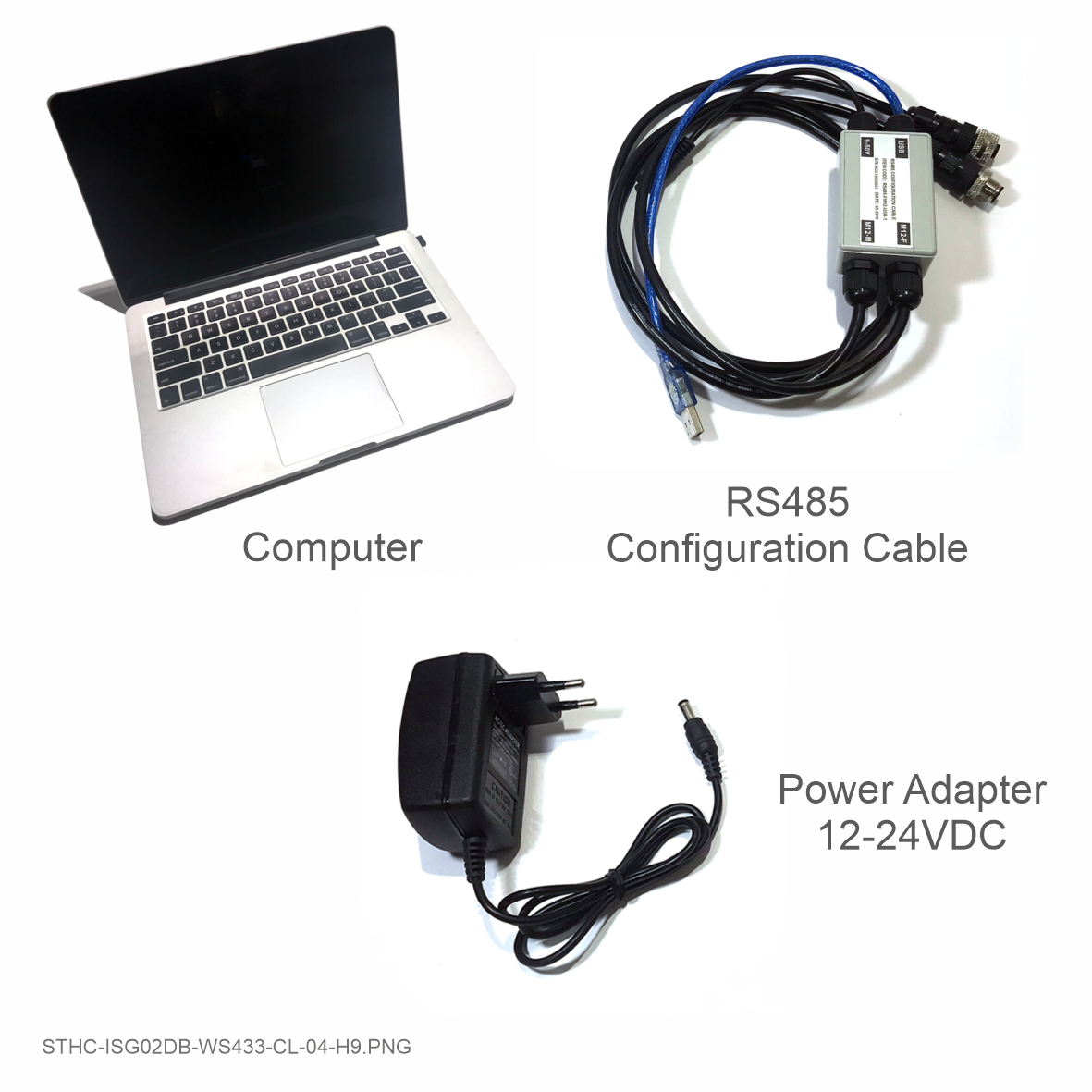
Step 1: Connect iConnector to RS485 - configuration cable via and power supply iConnector
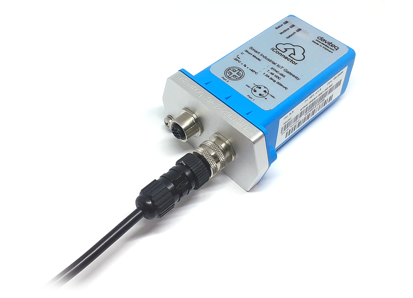 |
|
 |
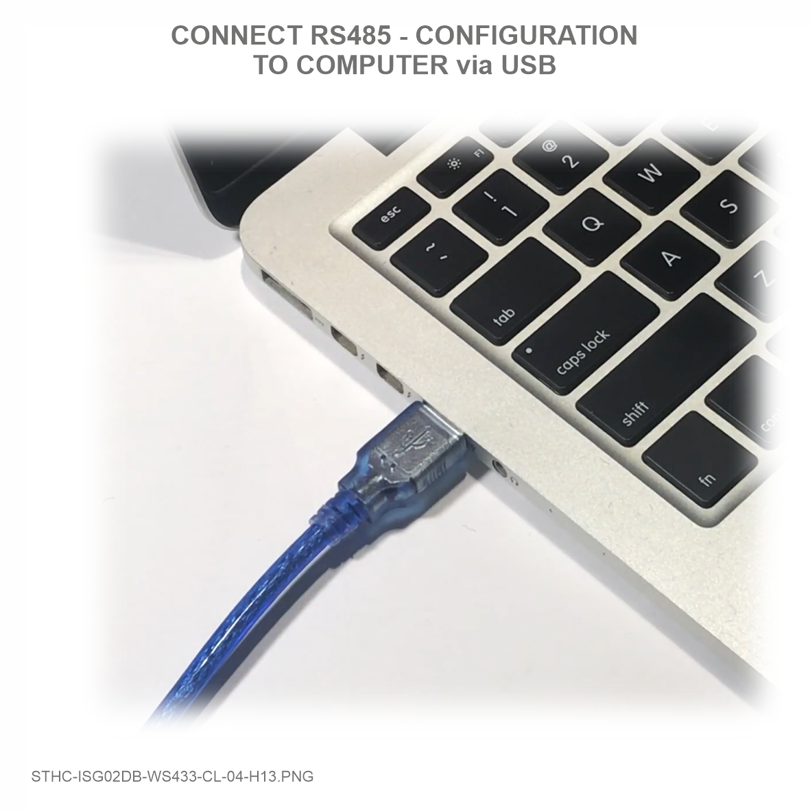 |
Step 2: Open Modbus tool on PC
You can download iConnector Configuration Tool with the following link:
https://filerun.daviteq.com/wl/?id=lNjzZbDo7Jwyr1x8DAD3x620tNK5u8lF
How to use the Modbus configuration software
Step 3: Open Modbus tool on PC
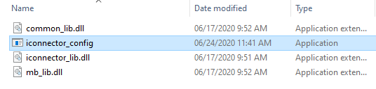
Unzip file and run file application "iconnector_config"
- Choose COM Port (the Port which is USB cable plugged in)
- Set the BaudRate: 9600, Parity: none
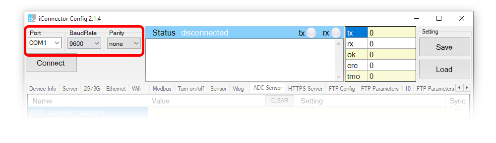
• Write in the Setting column the data to be configured into iConnector;
• Click Sync to synchronize data into iConnector;
• After synchronizing the data into iConnector, if the data displayed in the Value column shows the corresponding data, the configuration is completed.
SIM CARD CONFIGURATION
Based on the information of the mobile carrier that provides the SIM card, we configure data such as APN, username, password on the 2G/3G tab.
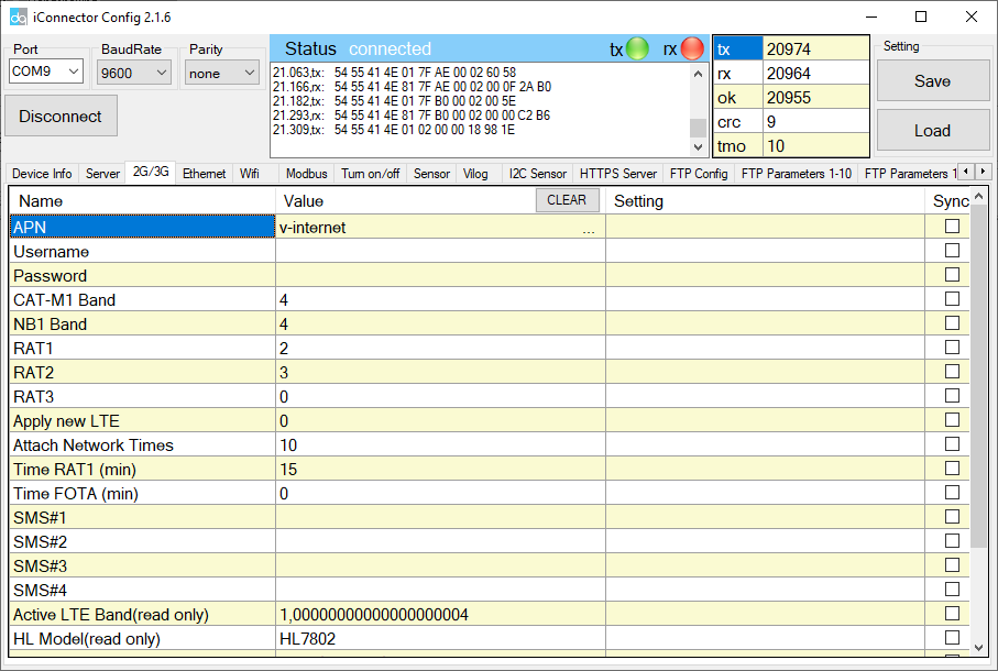
4.2.1 Configure CAT-M1 Band and NB1 Band
<bnd bitmap> Band bitmap in hexadecimal format without the 0x prefix.
This is the logical representation of 1 << (BandNumber - 1).
(Currently only used for RAT CAT-M1 and NB-1.)
|
0000 00000000 00000000 |
Not available |
|
0000 00000000 00000001 |
LTE Band 1 (2000 MHz) |
|
0000 00000000 00000002 |
LTE Band 2 (1900 MHz) |
|
0000 00000000 00000004 |
LTE Band 3 (1800 MHz) |
|
0000 00000000 00000008 |
LTE Band 4 (1700 MHz) |
|
0000 00000000 00000010 |
LTE Band 5 (850 MHz) |
|
0000 00000000 00000080 |
LTE Band 8 (900MHz) |
|
0000 00000000 00000100 |
LTE Band 9 (1900MHz) |
|
0000 00000000 00000200 |
LTE Band 10 (2100MHz) |
|
0000 00000000 00000800 |
LTE Band 12 (700 MHz) |
|
0000 00000000 00001000 |
LTE Band 13 (700 MHz) |
|
0000 00000000 00010000 |
LTE Band 17 (700 MHz) |
|
0000 00000000 00020000 |
LTE Band 18 (800MHz) |
|
0000 00000000 00040000 |
LTE Band 19 (800MHz) |
|
0000 00000000 00080000 |
LTE Band 20 (800MHz) |
|
0000 00000000 01000000 |
LTE Band 25 (1900MHz) |
|
0000 00000000 02000000 |
LTE Band 26 (800 MHz) |
|
0000 00000000 04000000 |
LTE Band 27 (800 MHz) |
|
0000 00000000 08000000 |
LTE Band 28 (700MHz) |
|
0002 00000000 00000000 |
LTE Band 66 (1800MHz) |
configure multiple bands, add them up according to hexadecimal.
For example: Configure band 2, 3, 4, 5, then add (0x02 + 0x04 + 0x08 + 0x10) = 0x1E
=> Band configuration is 1E (the leading zeros can be removed)
4.2.2 RAT1 configuration
|
0 |
Configuration running Cat-M1 only, not using RAT2, RAT3 |
|
1 |
Cat-M1 |
|
2 |
NB1 |
|
3 |
GPRS |
4.2.3 RAT2 configuration
|
0 |
Not using RAT2, RAT3 |
|
1 |
Cat-M1 |
|
2 |
NB1 |
|
3 |
GPRS |
4.2.4 RAT3 configuration
|
0 |
Not using RAT3 |
|
1 |
Cat-M1 |
|
2 |
NB1 |
|
3 |
GPRS |
4.2.5 Configure Apply new LTE
- After configuring we write down 1 to apply the new configuration, go back to RAT1. After execution, ICT will automatically reset to 0.
4.2.6 Configure Attach Network Times
- Number of attempts to connect to 1 RAT before switching to the next RAT when connection failed;
- RAT1 => RAT2 => RAT3 => RAT1;
- One connection attempt takes about 10-20 seconds.
4.2.7 Configure Time RAT1 (min)
- Every minute of time_RAT1 will try to reconnect with RAT1 if it is currently running in RAT2 or RAT3. Minimum 15 minutes.
4.2.8 Configure Time FOTA (min)
- After time_FOTA minutes will connect to the server of Sierra Wireless 1 time to check for FW updates or not;
- Write 0 to turn off FOTA.
→ Use to update the new FW for the HL7802 modem.
4.3 Operational principle of RAT1, RAT2, RAT3
When the ICT is started, it will connect to RAT1 first. If the connection is successful, it will run at RAT1.
- If the ICT connecting to RAT1 fails, it will try to reconnect (Attach Network Times) times.
- If not, it will be transferred to RAT2.
- If successfully connected to RAT2 it will run at RAT2.
- If the ICT connecting to RAT2 fails, it will try to reconnect (Attach Network Times) times.
- If not, it will be transferred to RAT3.
- If successfully connected to RAT3 it will run at RAT3.
- If the ICT connection to RAT3 fails, it will try to reconnect (Attach Network Times) times.
- If not, it will be transferred to RAT1.
- If successfully connected to RAT1 it will run at RAT1.
- Every time_RAT1 minutes will try to reconnect to RAT1 if it is currently running at RAT2 or RAT3.
- Write 1 to Apply new LTE then ICT will try to reconnect to RAT1 immediately (if it is currently running at RAT2 or RAT3).
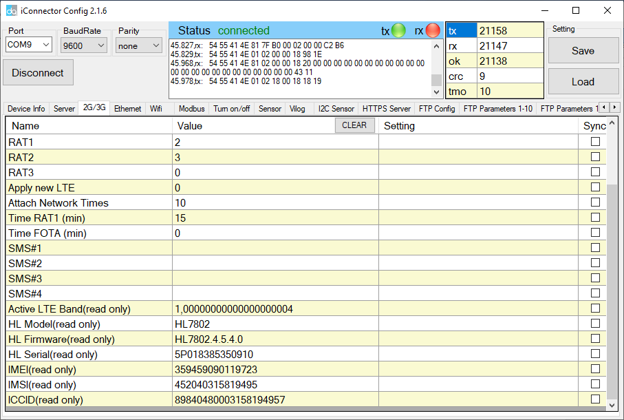
4.4 The information of modem, sim
Memmaps information of modem, sim in the table below:
|
ADDRESS (in decimal) |
ADDRESS (in hex) |
LENGTH (in byte) |
TYPE | NAME | DESCRIPTION | UNIT | Server |
|
160 |
A0 |
20 |
string |
modem hl serial |
R |
||
|
180 |
B4 |
20 |
string |
imei |
identification text for determination of the individual ME |
R |
|
|
200 |
C8 |
20 |
string |
imsi |
International Mobile Subscriber Identity |
R |
|
|
220 |
DC |
20 |
string |
iccid |
SIM Card Identification |
R |
|
|
240 |
F0 |
16 |
string |
modem hl fw ver |
R |
||
|
9056 |
2360 |
10 |
string |
Model identifier |
R |
||
|
9066 |
236A |
22 |
string |
Active LTE Band |
R |
Active LTE Band:
Active LTE Band: see which RAT is running, which band.
• Number 1 at the beginning of the sequence is NB1.
• Number 4 is band 3 (1800 MHz).
NOTE:
The display of RAT differs from the configuration of Cat-M1, NB1, GPRS as 0, 1, 2; NOT 1, 2, 3.
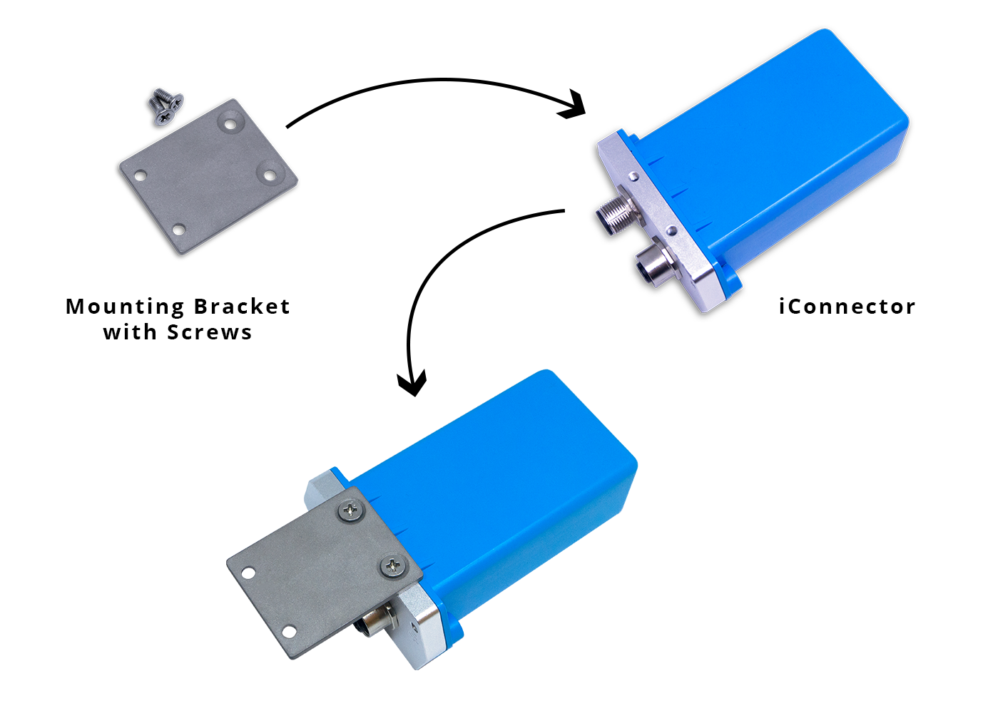
5. Installation
5.1 Installation location
Installed on a wall or in non-metal box. The bracket will be fixed on the wall or material with a planar surface with 2 x M4 screws;
ATTENTION:
DO NOT install the iConnector inside a completed metallic box or housing, because the RF signal can not pass through the metallic wall. The housing is made from Non-metallic materials like plastic, glass, wood, leather, concrete, cement…is acceptable.
5.2 IO Wiring
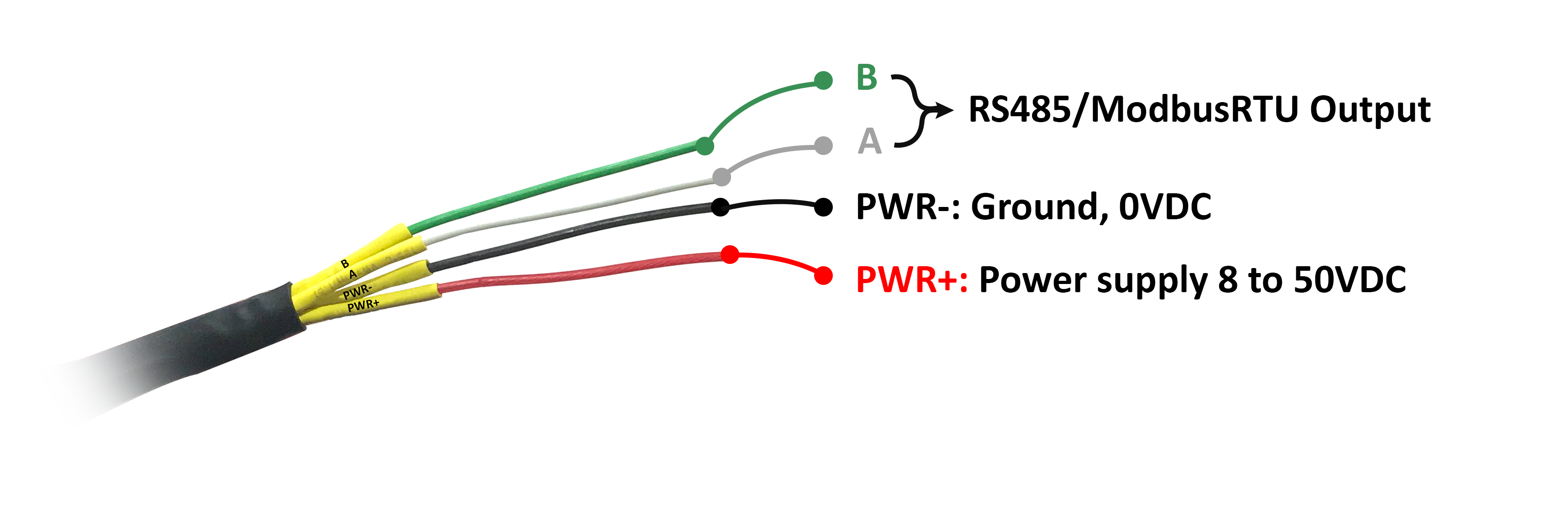
5.2.1 Connect Power Supply and Modbus
- Connect PWR+ and PWR- to 7..48VDC power supply via M12 Male connector
- Connect A and B to RS485 connection.
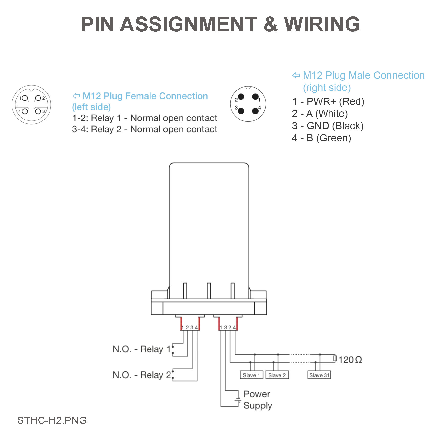
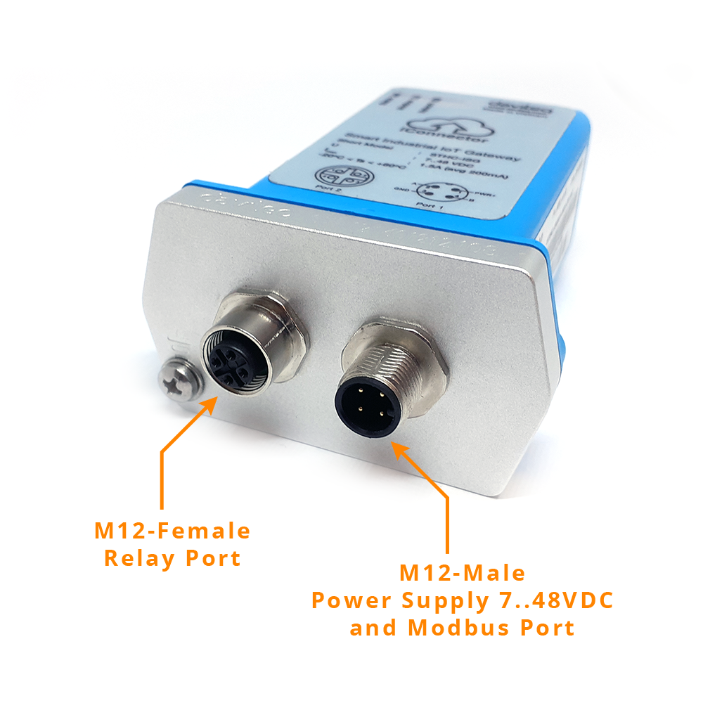
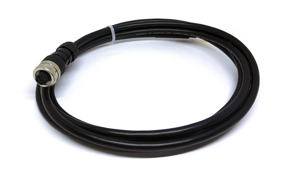
Use M12 female connection cable to connect to iConnector
5.3 Battery installation
Steps for battery installation:
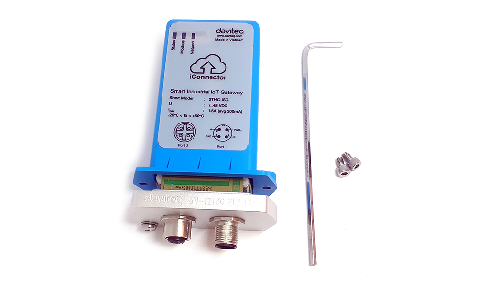
Step 1: Using L hex key to unscrew M4 screws at the side of housing
Step 2: Carefully pull out the top plastic housing in the vertical direction
Step 3:Attach the battery connector of the lithium battery and the circuit board together
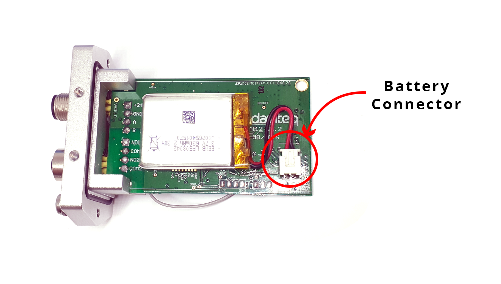
Step 4: Insert the top plastic housing and locking by L hex key
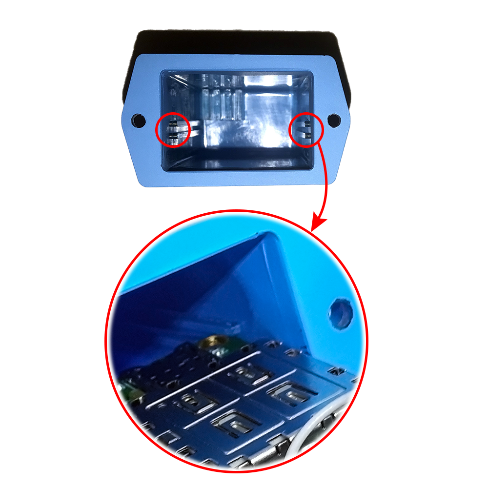
(NOTE: When reinstalling the cover, pay attention to put the PCB edge into the middle slot of the box inside as shown below)
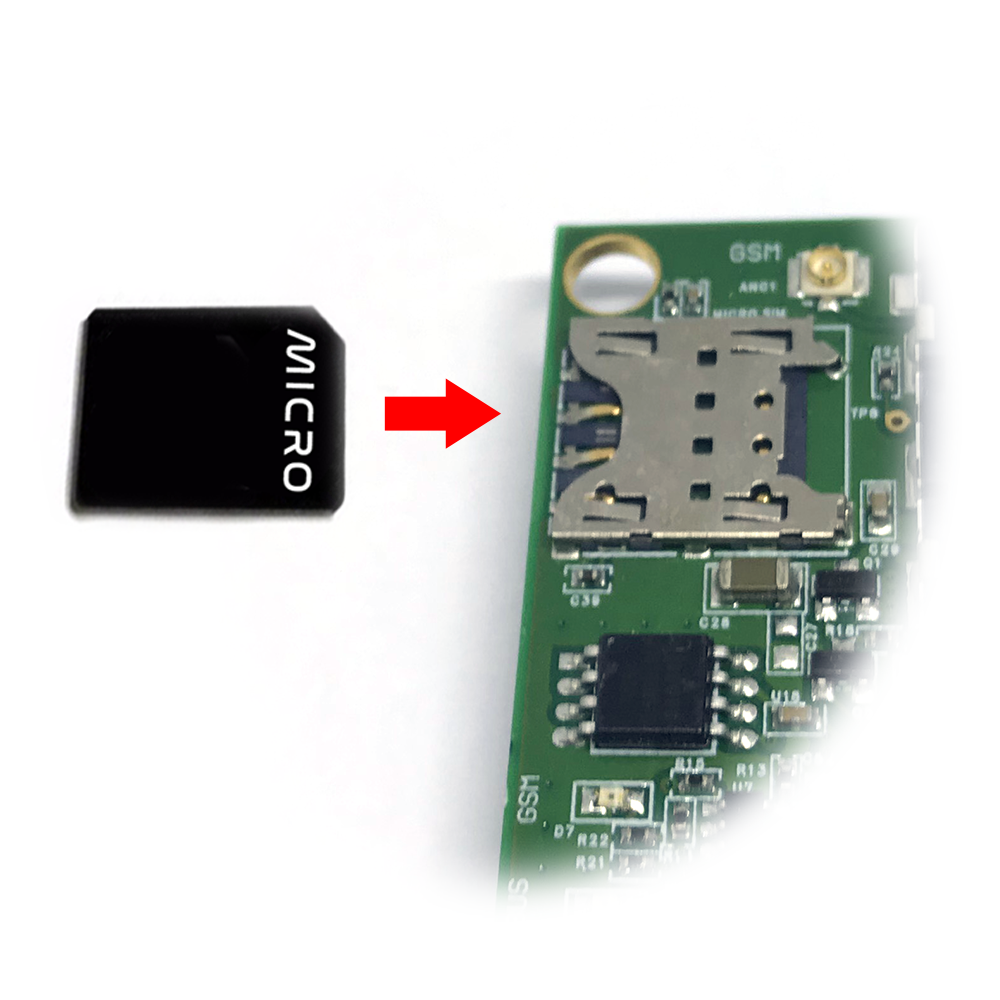
5.4 Insert SIM card
- Open iConnector cover with hex key and install the SIM card;
- Please insert the SIM in the direction printed on the label.
6. Example application
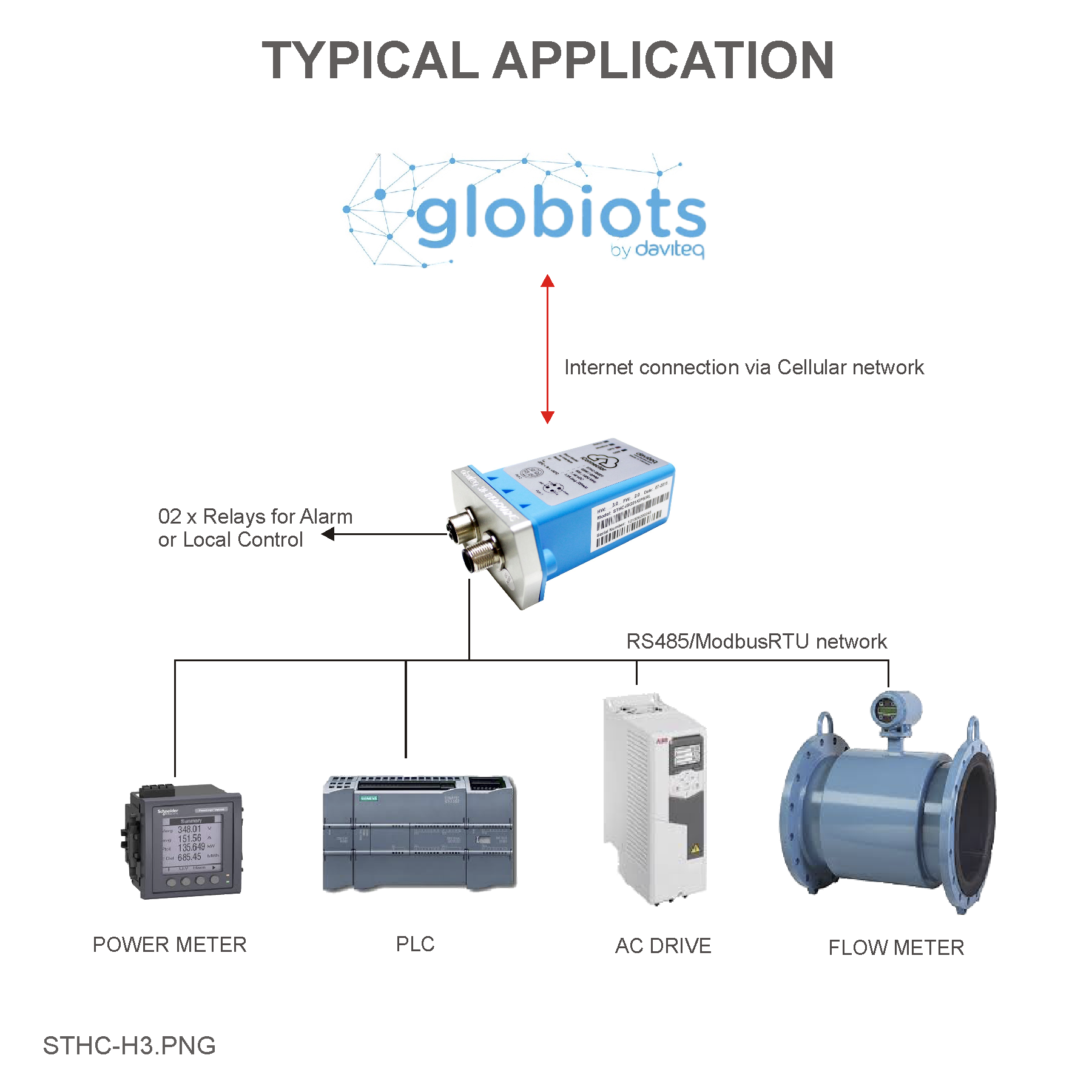 |
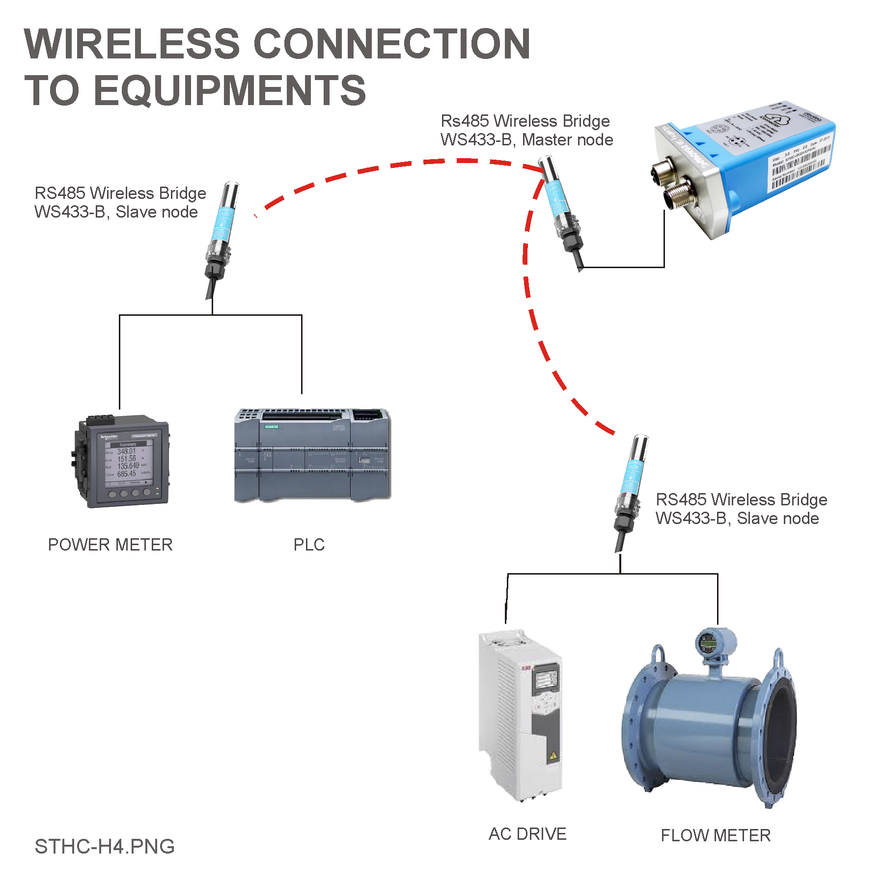 |
7. Troubleshooting
| No. | Phenomena | Reason | Solutions |
| 1 | Data does not go to server, N/A | iConnector lost connection with server |
|
| 2 |
|
|
|
| 3 | The data posted on Globiots is wrong, the phenomenon of value is changed abnormally continuously | Configuration parameter & modbus command is wrong | Check and correctly configure parameters & modbus commands |
| 4 |
|
Lost power iConnector | Check iConnector power supply |
| 5 | Led network does not light |
|
|
8. Support contacts
|
Manufacturer
Daviteq Technologies Inc Email: info@daviteq.com | www.daviteq.com
|
Distributor in Australia and New Zealand
Templogger Pty Ltd Tel: 1800 LOGGER Email: contact@templogger.net |

No Comments