Manual for Indoor LoRaWAN Gateway - GWIND
.png)
Thank you very much for choosing Daviteq Wireless Sensors. We are the leading wireless sensor manufacturer in the World. We have a wide range of wireless sensors which support different connectivity like LoRaWAN, Sigfox, Sub-GHz, NB-IoT...Please find out more information at this link.
This manual is applied to the following products
| Item code | HW Version | Firmware Version | Remarks |
| GWIND-9 | 1.0 | 1.0 |
To use this product, please refer step by step to the below instructions.
1. Quick Guide
Reading time: 10 minutes
Finish this part so you can understand and put the sensor in operation with the default configuration from the factory.
1.1 What is the GWIND ?
GWIND is a LoRaWAN Gateway designed for indoor installation, used in projects such as Smart Factory, Smart Agriculture, Smart Building, Smart Residential Area, Smart City... It supports simultaneously 8 connection channels to help receive a large number of packets from surrounding LoRaWAN sensors. The connection distance to the LoRaWAN sensors is up to 10 Km (depending on the environment and sensor types). It supports common communications such as Ethernet, LTE, WiFi. LoRa frequency support 863~870 MHz / 902~928 MHz.
This LoRaWAN Gateway is widely used in applications such as reading water meters, electricity meters, gas meter, environmental monitoring, smart farms, smart factories...
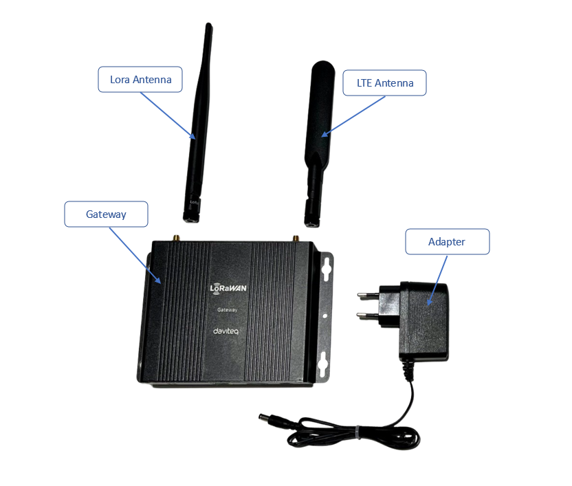
1.2 What's in the package?
The package includes:
01 x LoraWAN Gateway
01 x Lora Antenna
01 x LTE Antenna
01 x Adapter
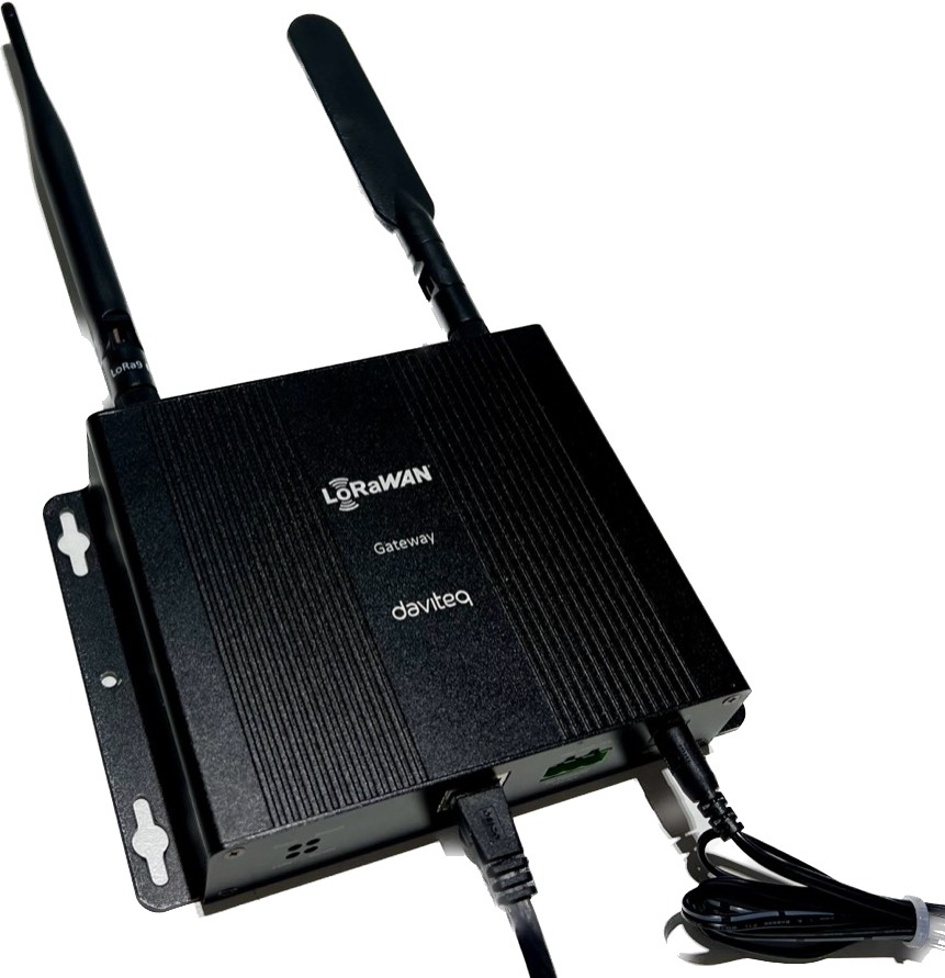
1.3 Product Overview
1.3.1 I/O Ports
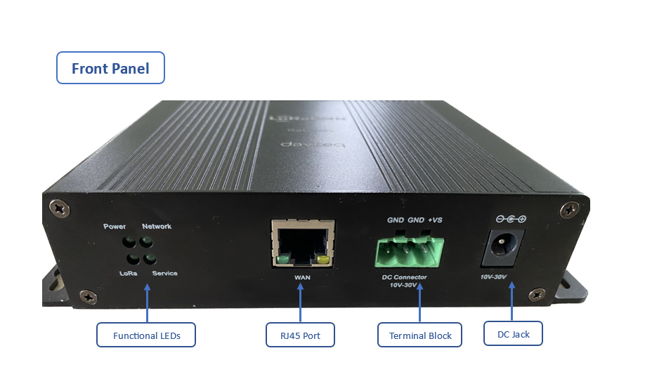

1.3.2 LED Functions
| LED Functions | Constant | Flashing | Off |
| Power | Power On | Booting /OTA | OFF |
| Internet | Internet Available | Checking Internet | RFU |
| Service | LNS Connected | RFU | LNS Not Connected |
| LoRa | LoRa Working | Initializing | LoRa Not Working |
1.3.3 Reset Button
- Reboot:
By pressing and holding the RESET Button, the Power LED will start flashing. The “reboot” procedure will be triggered when the RESET Button is released while the Power LED light is
flashing. - Restore to Default:
By pressing and holding the RESET Button, the Power LED will start flashing. The “restore to default” procedure will be triggered when the RESET Button released after the Power LED
light becomes constant.
1.4 Installation
Startup the LoraWAN Gateway through the following steps
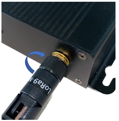
Step 1: Install the antennas of the LoRaWAN Gateway
Install the antennas in the correct position. Make sure the antennas and Gateway are tightly connected.
Step 2: Insert the SIM card into the LoRaWAN Gateway
Remove the plastic plate in the SIM socket, then insert the SIM card into the socket with correct SIM direction.
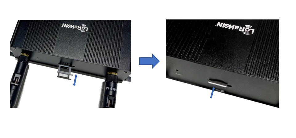
Pay attention to the direction of the SIM
Note: If the gateway use only Ethernet port to connect to Network Sever, skip step 2
Step 3: Connect the Ethernet cable and power up the Gateway
Connect the Ethernet cable into RJ45 port. After that, Connect the power adapter provided to the DC jack In. The gateway will automatically turn on after powering up.
1.5 Configure the LoRaWAN Gateway
1.5.1 GUI Access
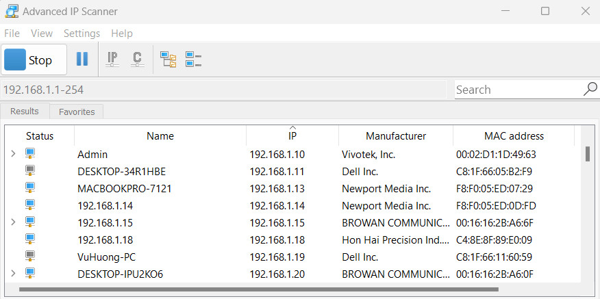
Default mode of Daviteq Gateway is DHCP. Once gateway is turned on through plugging in the DC adapter, it will automatically link to available servers. Gateway’s IP address can be found from the DHCP server. Access Gateway Web UI via the DHCP IP on browser. The default username is “admin”, and the password can be found on the back label.
To access the GUI, follow these steps:
Step 1: Use a computer to connect to the network that the gateway is connected. The computer can connect to that network via WiFi or Ethernet.
Step 2: Use the IP scanning software to find the IP address of the gateway based on its Mac address that can be found on the back label.
Access this link to get a free IP scanning software on the internet
Step 3: Enter the IP address of the gateway in the web browser to access the configuration interface.
For example, If the IP address of the Gateway is 192.168.1.15 , you should enter exactly that information in web browser, then the GUI will be displayed.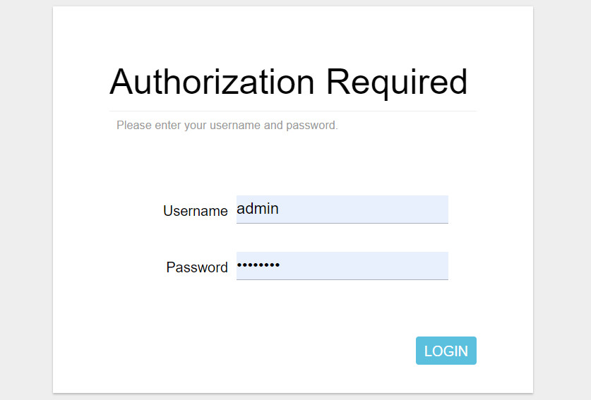
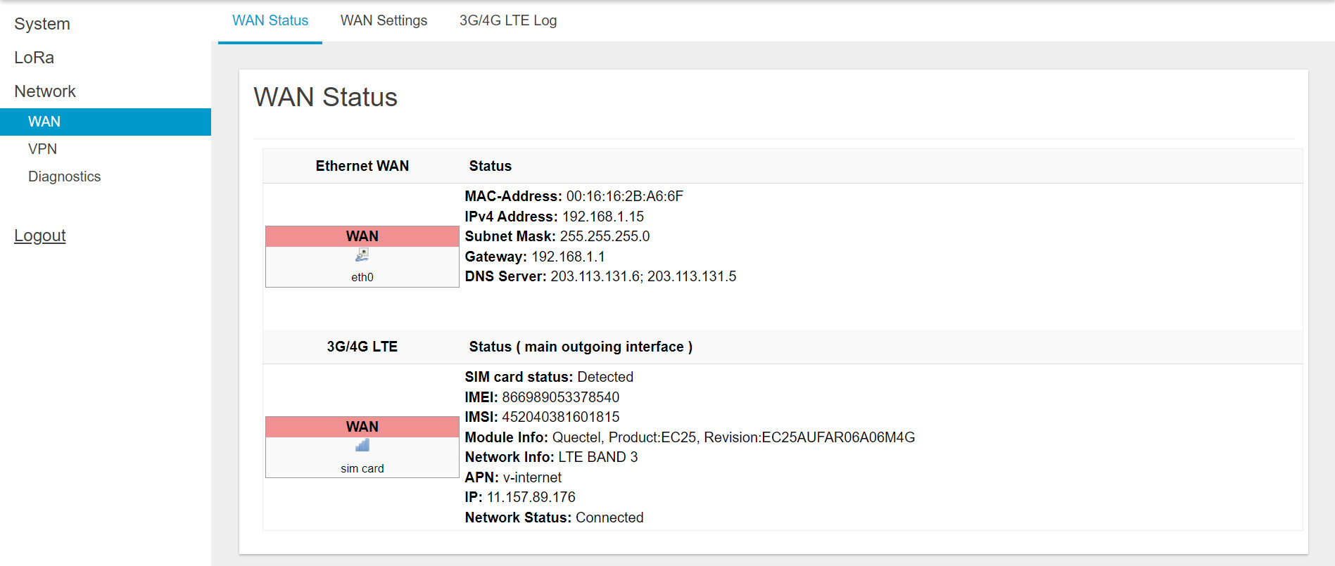
1.5.2 WAN configuration
The purpose of this category is to view current WAN settings. This category is further divided into three sectors: WAN Status, Wan Settings and 3G/4G LTE Log.
- WAN Status
The current network status will be shown on this page.
- WAN Settings
Daviteq Gateway supports three WAN Modes: Ethernet WAN, 3G/4G LTE and Dual WAN (Ethernet+3G/4G). Default mode of Daviteq Gateway is Dual WAN.
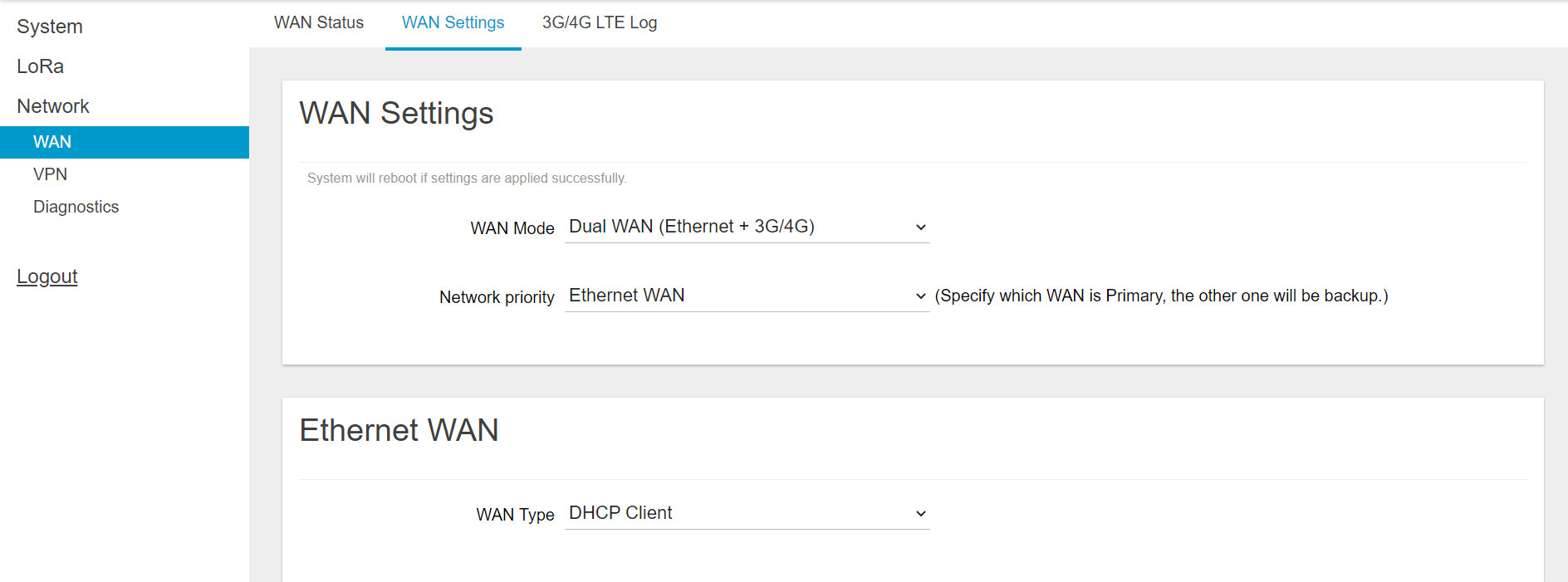
Note: Configure “APN” information according to mobile service provider requirements.
1.5.3 Lora Settings
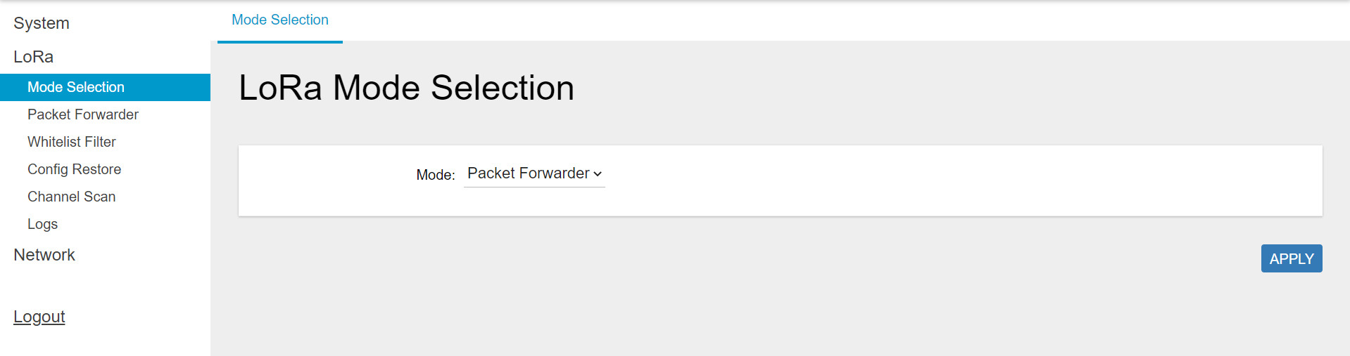
- Mode selection
At the field, choose the "Packet Forwarder" option and click the "APPLY" button to Enable the Packet Forwarder mode. After applying the setting, the "Packet Forwarder" field can be found on the left menu.
- Packet Forwarder configuration
Select Packet Forwarder in the left menu, then choose Gateway Info. This page is for setting up the LoRa configuration including Gateway ID, Server Address, Server Uplink Port, Server Downlink Port, Keep-Alive Interval, Statistics Display Interval, and Push Timeout.
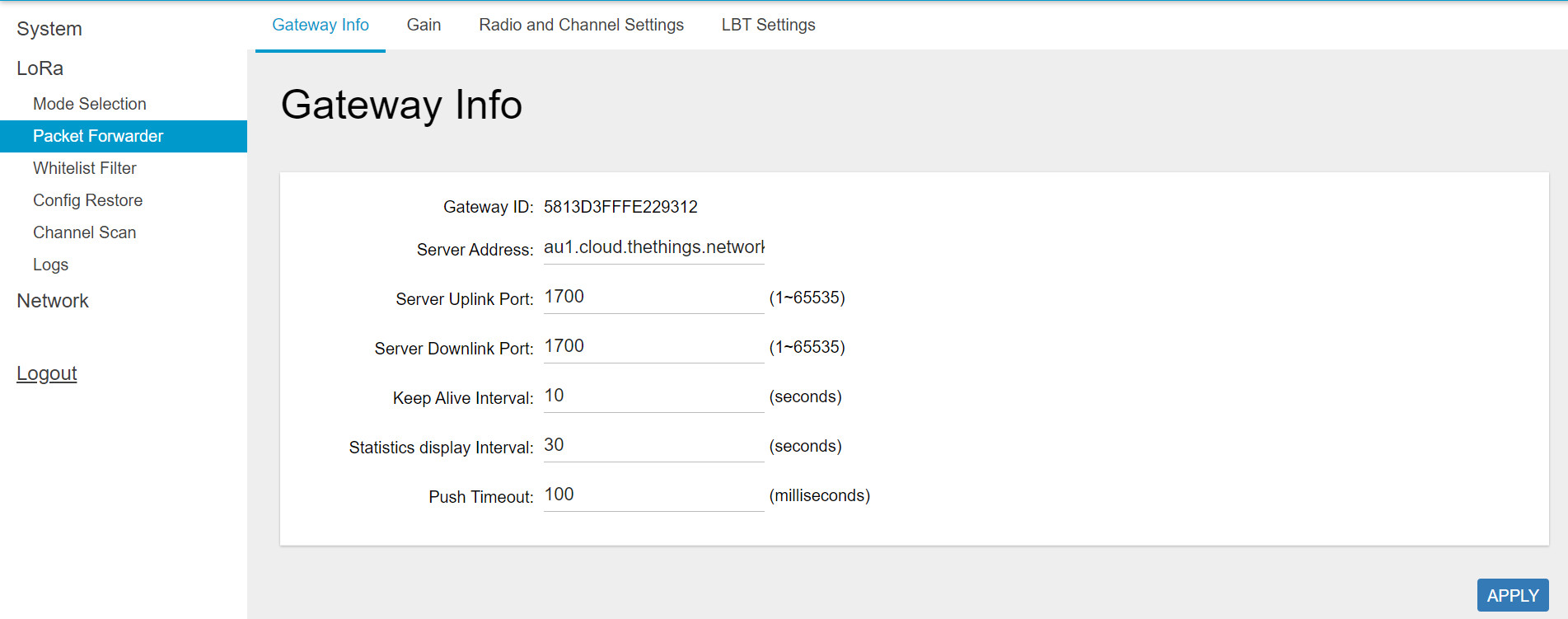
Need to properly configure the Server Address, Server Uplink Port, and Server Downlink Port fields. These information depend on the Network server.
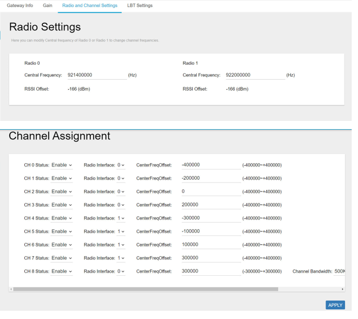
- Radio and Channel Settings
This page is for configuring the radio 0 and radio 1 configurations of Lora, including Central Frequency, Channel Status, and Center frequency offset. The frequencies and channels are regulated by the lora-alliance, region and the network server. Below is an example of the configuration of the frequency AS923-2.
1.6 Add the LoraWAN Gateway to Network Server
To give an example, please follow the instructions in this link to add LoraWAN gateway to The things Stack network server.
2. Product specification
|
LoRaWAN Specification |
LoRaWAN 1.0.3 |
|
Frequency Band |
Select 863~870 MHz / 902~928 MHz |
|
Number of Channels |
Up to 8 concurrent channels for LoRa transmission |
|
LoRa Transmit Power |
0.5W (up to 27 dBm) |
|
LoRa Receive Sensitivity |
Down to -142 dBm (conducted) |
|
LoRa Software |
Standard and LRR Actility |
|
Operating Temperature |
-10°C ~ 55°C |
|
Storage Temperature |
-20°C ~ 60°C |
|
Power Supply |
DC 12 V/1.5 A-Power Adaptor / DC 10~30 V 3-Pin Connector Power supply / Passive PoE 10~30 V |
|
4G LTE |
LTE Cat 4 or Cat M1/NB2 |
|
Interfaces |
1 WAN RJ45 10/100Mbps (w/ passive PoE capability), 1 SIM card slot (2FF), 1 DC jack in / 1 terminal block |
|
Antenna Type |
1 x external LoRa antenna, 1 x External antenna for LTE |
|
Dimensions |
L:120 x W:136 x H:35mm |
|
Weight |
0.4 kg |
|
Vietnam Type Approval |
pending |
3. Warranty and Support
For warranty terms and support procedures, please refer to this link.
4. References
Use-cases:
Case studies:
White-papers:
END.
No Comments