2. QUICK GUIDE
Reading time: 20 minutes
Finish this part so you can understand and put the device in operation with the default configuration from the factory.
2.1. What is the PINEX?
PineX is an industrial-grade outdoor LoRaWAN® Gateway, designed to operate reliably in the harshest environments—from scorching deserts to freezing Arctic conditions, and even hurricane-force winds up to 200 km/h. With IP67-rated waterproof and dustproof protection, an extended temperature range of -40°C to +70°C, and Dual LoRa Antennas for extended coverage, PineX ensures uninterrupted, long-range connectivity even in extreme weather conditions. Supporting all global LoRaWAN frequency bands, PineX integrates a built-in Network Server, Node-RED, and VPN security, enabling fast, cost-efficient, and secure IoT deployments. Designed for Smart Cities, Industrial Facilities, Smart Agriculture, and remote IoT applications, PineX is the ultimate rugged, high-performance LoRaWAN Gateway for mission-critical operations.
2.2. What's in the package?
2.2.1. Advanced version
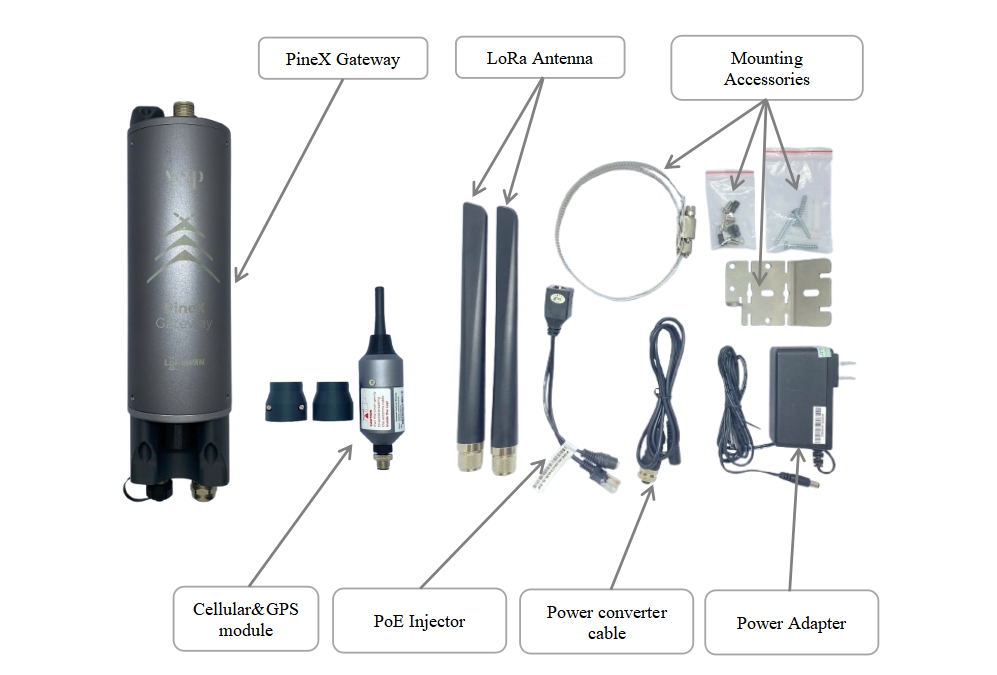
The package includes:
01 x LoraWAN PINEX Gateway
02 x Lora Antenna
01 x Cellular & GPS module (optional)
01 x Power Adapter
01 x Converter cable
01 x PoE Injector
01 x Mounting Accessories
2.2.2. Economy version
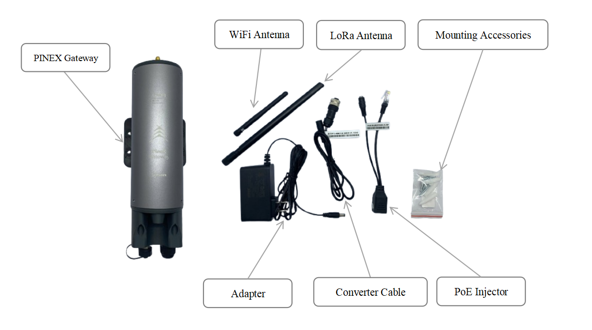
The package includes:
01 x LoraWAN PINEX Gateway
01 x Lora Antenna
01 x WiFi Antenna (optional)
01 x Power Adapter
01 x Converter cable
01 x PoE Injector
01 x Mounting Accessories
2.3. Product Overview
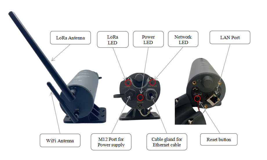
- LED Functions
| LED Functions | Constant | Flashing | Off |
| Power | Power On | None | OFF |
| Network | Initializing, High network traffic | Internet Available | Disconnected |
| LoRa | LoRa Working | Initializing | LoRa Not Working |
Some configuration such as Packet Forwarder settings, VPN settings, WAN settings will be restored to factory defaults when reset process completely taken.
Use a pointed stick to poke the button inside the hole and hold for 5 seconds. The gateway will automatically perform reset process. The whole process will take a few minutes.
Reset the device only when absolutely necessary
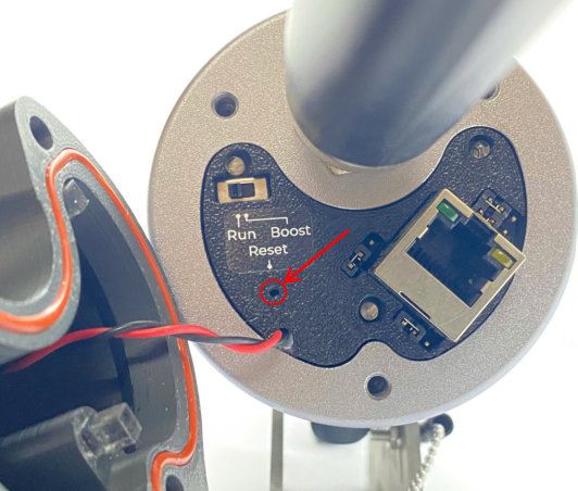
- Function switch
The switch have to be in Run position in normal operation. Boost mode uses for firmware update.
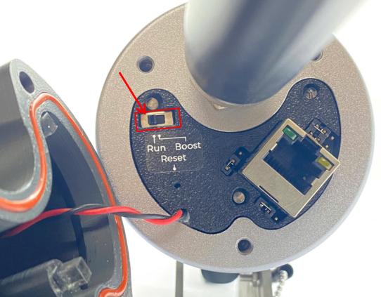
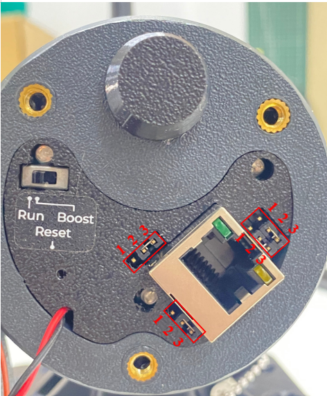
- Jumpers
There are four jumpers. Default position of four is connecting port 1 and 2.
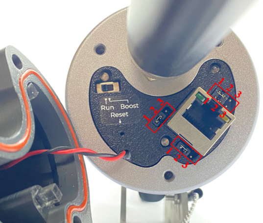
Only change the jumper position when the gateway doesn't support PoE+ source 802.3atbut you want to power the gateway through ethernet cable as the below diagram.
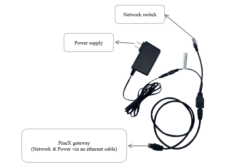
To power the gateway through Ethernet cable as the above diagram, four jumpers have to change to connecting port 2 and port 3 as below
WARNING:
If gateway is powered through Ethernet cable as the above diagram BUT four jumpers ARE NOT be changed to connecting port 2 and port 3 as below, the gateway will be damage/defective
It is only applied for the gateway version that doesn't support PoE+ source 802.3at
2.4. Installation
Startup the LoraWAN Gateway through the following steps
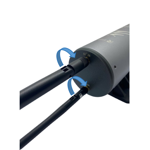
Step 1: Install the antenna of the LoRaWAN Gateway
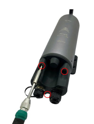
Step 2 :Use the screw driver to remove the three screws, then open the gateway cover.
Step 3: Connect the Ethernet cable to the Gateway
Connect the Ethernet cable into LAN port.
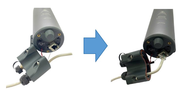
Step 4: Close the gateway's cover, then use the screw driver to lock the 3 screws.
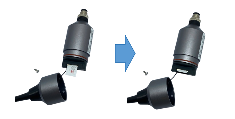
Step 5: Install the SIM card to Cellular & GPS module (optional)
- Use the screw driver to remove the screw in the module, then carefully open the cap

- Insert the SIM card into the slot, pay attention to the direction of the Sim card
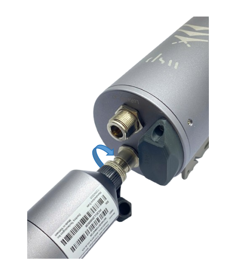
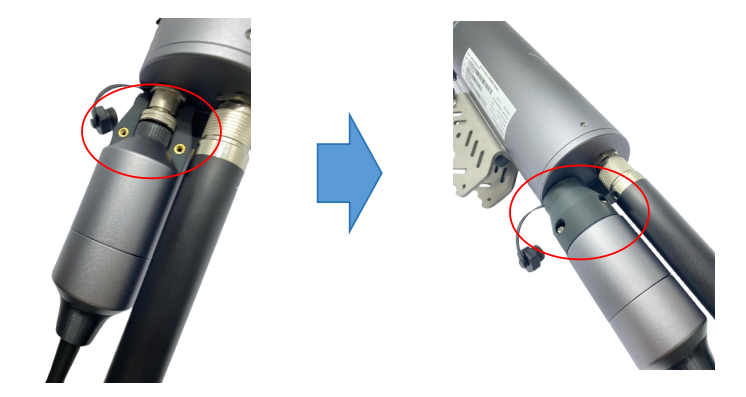
Step 6: Install the Cellular & GPS module to the gateway (optional)
- Plug the Cellular & GPS module to the M12-FM port at the top of the gateway, then tighten the connector
- Install the connection protection accessories
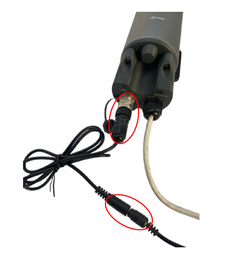
Step 7 : Power up the Gateway through M12 port
2.5. Mounting
-
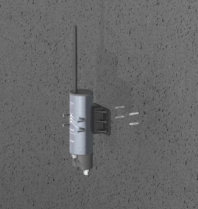
Economy version
Step 1: Select the installation location. The surface must be flat.
Step 2: Based on the dimensions of the gateway's base, drill four holes into the wall. Then, insert wall anchors into the drilled holes.
Step 3: Use screws to secure the gateway onto the drilled surface.
-
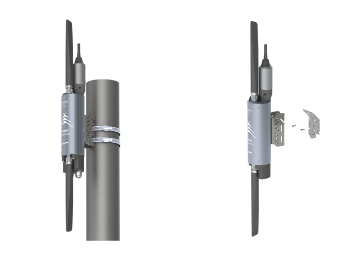
Advanced version
There are two methods for mounting the gateway
1. Mount the gateway to the steel pole with a hose clamp
2. Attach the bracket to the wall, then mount the gateway on the bracket.
2.6. Configure the LoRaWAN Gateway
2.6.1 GUI Access
By default, the gateway is configured to use DHCP. Therefore, it must be connected to a network with an active DHCP server in order to access the Web GUI.
If the gateway is to be used in a static IP network without DHCP, it must firstly be connected to another active DHCP server to access the configuration interface to configure static IP for the gateway. Once the initial configuration is complete, the gateway can then be moved to the static IP network. Details of static IP configuration for the gateway are in sub-section of WAN SETTINGS in section of 2.2.6.2 Network WAN configuration
In some company with strict IT regulations, the gateway MAC address must be added to company network white list for proper connection.
To access the GUI, follow these steps:
Step 1: Use a computer to connect to the network that the gateway is connected. The computer can connect to that network via WiFi or Ethernet.
Step 2: Use the IP scanning software to find the IP address of the gateway based on its Mac address that can be found on the back label.
Access this link to get a free IP scanning software on the internet
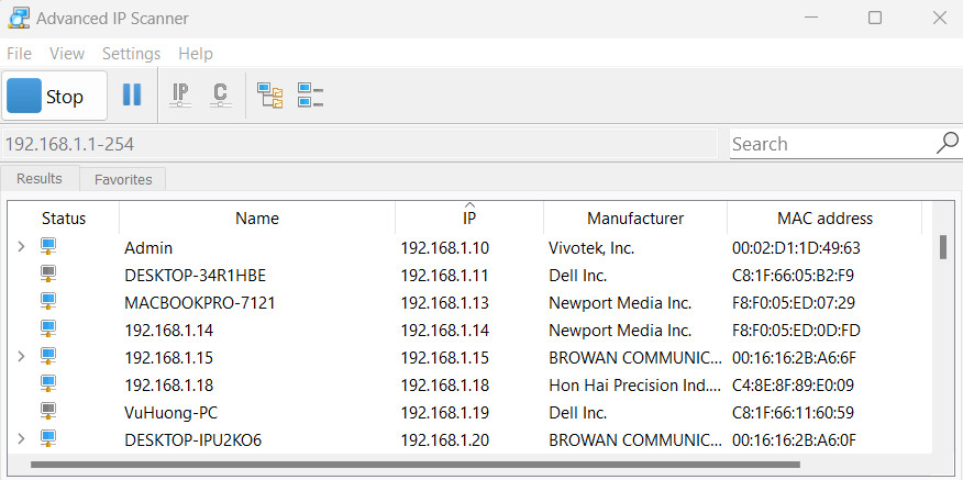
Step 3: Enter the IP address of the gateway in the web browser to access the configuration interface.
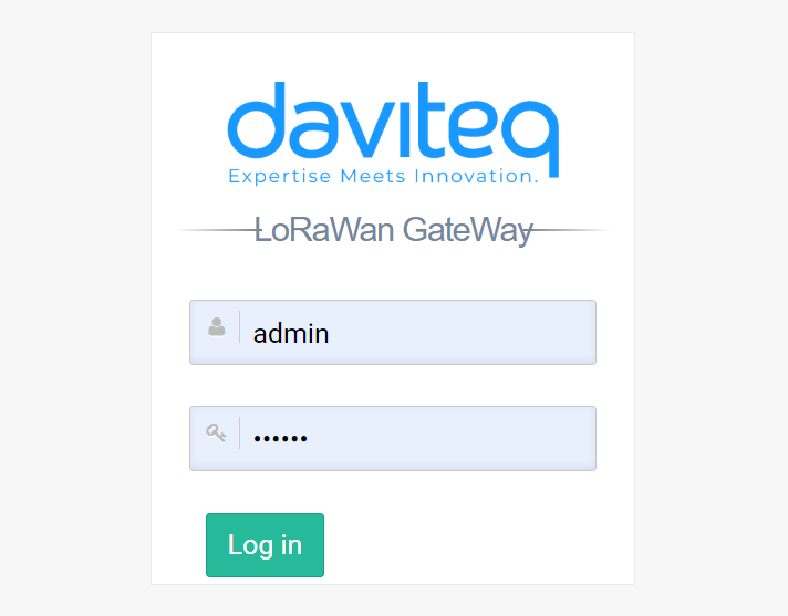
Must add port 4050 after the IP address. For example, If the IP address of the Gateway is 192.168.1.21 , you have to enter 192.168.1.21:4050 in web browser, then the GUI will be displayed.
The default username is admin and default password is public. Please check updated username and password on the gateway label.
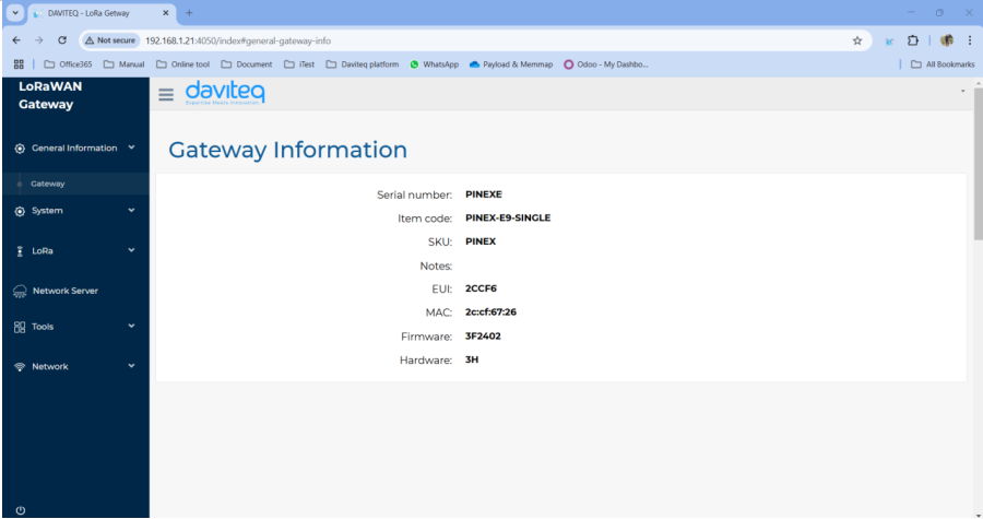
After login successfully, the general information of the gateway will be display at general information tab.
2.6.2 Network WAN configuration
This category shows current WAN settings. This category is further divided into three sectors: WAN Status, Data Statistics and WAN Settings.
-
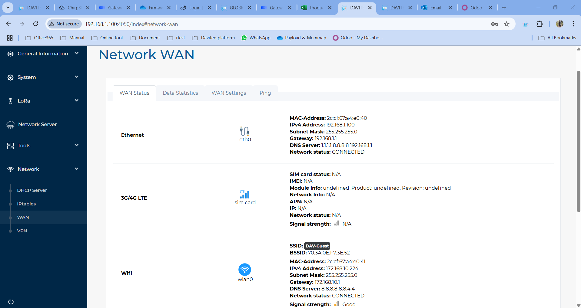
WAN Status
The current network status will be shown on this page.
-
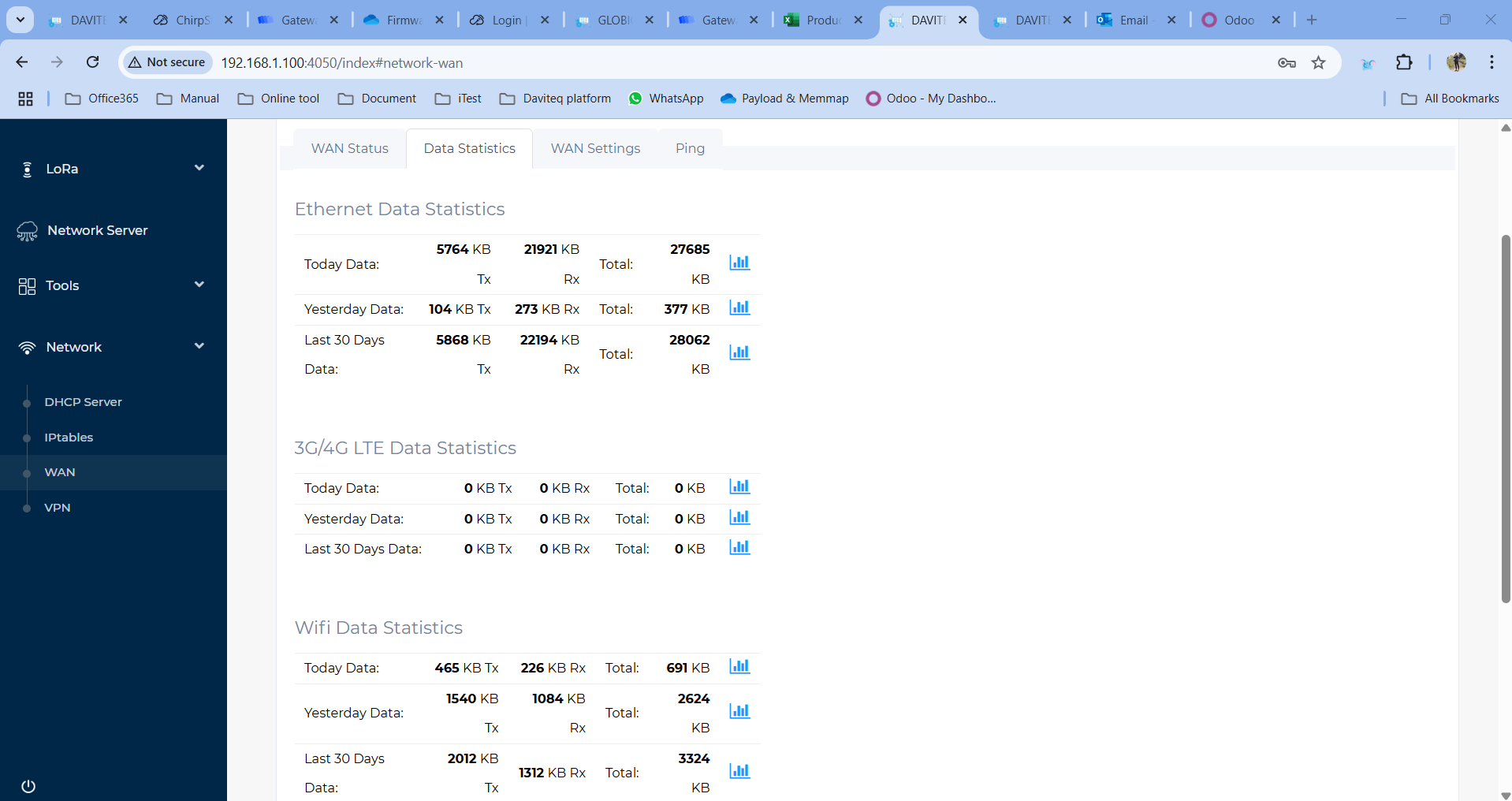
WAN Statistics
Statistics on the gateway's used data capacity are shown in this section
-
WAN Settings
Daviteq Gateway supports internet connectivity via both Ethernet , Wi-Fi (optional) or Cellular (optional).
The default Ethernet mode is DHCP.
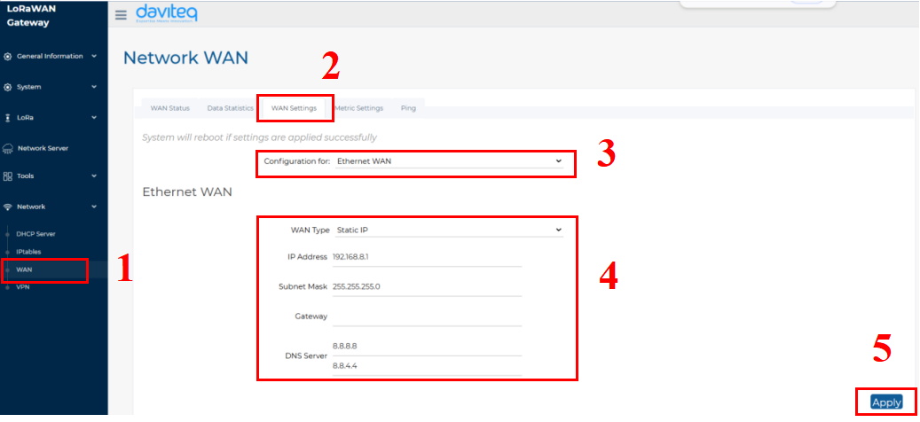
- Follow the steps below to set up the Ethernet network to static mode.
Step 1: In the Network section, select WAN.
Step 2: Click on the WAN Settings tab at the top.
Step 3: In the Configuration field, select Ethernet WAN
Step 4: Enter the Ethernet WAN information, including WAN Type, IP address, Subnet Mask, Gateway and DNS server
Step 5: Click the Apply button to save and apply the new configuration.
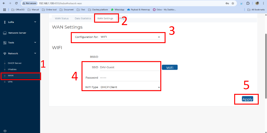
- Follow the steps below to set up the Wi-Fi network for the gateway:
Step 1: In the Network section, select WAN.
Step 2: Click on the WAN Settings tab at the top.
Step 3: In the Configuration field, select Wi-Fi.
Step 4: Enter the Wi-Fi information, including SSID (Wi-Fi name), Password, and Wi-Fi Type (default: DHCP Client).
Step 5: Click the Apply button to save and apply the new configuration.
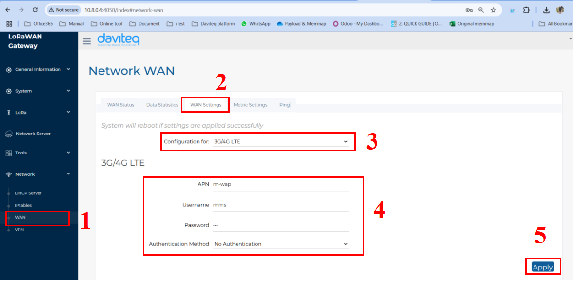
- Follow the steps below to set up the Cellular network for the gateway:
Step 1: In the Network section, select WAN.
Step 2: Click on the WAN Settings tab at the top.
Step 3: In the Configuration field, select 3G/4G LTE
Step 4: Enter the 3G/4G LTE information, including APN, Username, Password, and Authentication Method (base on the SIM card provider).
Step 5: Click the Apply button to save and apply the new configuration.
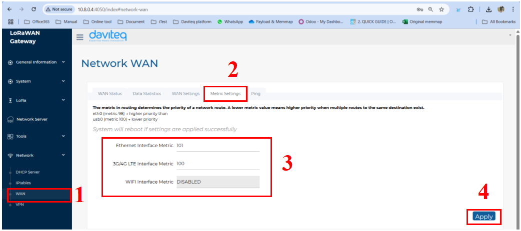
- Follow the steps below to set up network priority
The metric in routing determines the priority of a network route. A lower metric value means higher priority when multiple routes to the same destination exist. For example, 100 is higher priority than 101.
Step 1: In the Network section, select WAN.
Step 2: Click on the Metric settings tab at the top.
Step 3: Enter the the metric factor for available network.
Step 4: Click the Apply button to save and apply the new configuration.
2.6.3. Lora Settings
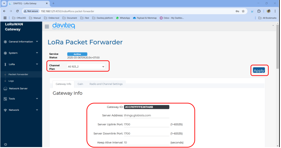
Package Forwarder
Select Packet Forwarder in the left menu, then choose Gateway Info. This page is for setting up the LoRa configuration including Channel Plan, Gateway ID, Server Address, Server Uplink Port, Server Downlink Port, Keep-Alive Interval, Statistics Display Interval, and Push Timeout
Need to properly configure the Server Address, Server Uplink Port, and Server Downlink Port fields. These information depend on the Network server.
Choose the channel plan for the gateway, then choose the Apply button at the bottom right to save the current configuration.
| Parameter name | Description | Default value |
| Channel Plan | The region refers to the specific geographical area where the gateway operates, following the LoRaWAN Regional Parameters defined by the LoRa Alliance | EU868 |
| Gateway ID | The Gateway ID (also known as DevEUI) is a unique identifier assigned to a LoRaWAN gateway. | Unique value |
| Server Address | The server address in a LoRaWAN gateway refers to the network server’s IP address or domain name that the gateway connects to for data transmission and management | localhost |
| Server Uplink Port | The server uplink port in a LoRaWAN gateway refers to the port number used to send uplink packets | 1680 |
| Server Downlink Port | The server downlink port in a LoRaWAN gateway is the port number used for receiving downlink packets | 1680 |
| Keep alive interval | The keep-alive interval is the time interval at which a LoRaWAN gateway sends periodic status messages (heartbeats) to the network server to indicate that it is active and connected. | 30 |
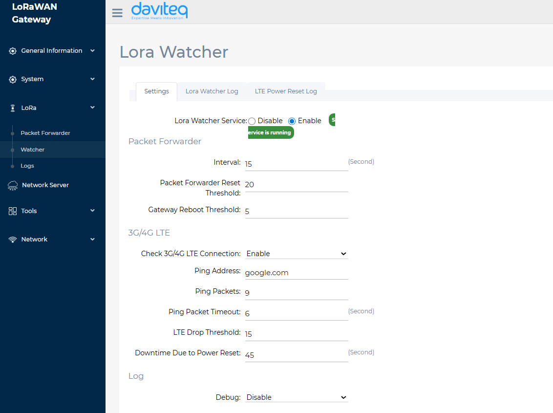
Watcher
- Packet Forwarder:
- Interval: Interval for checking the system log to verify successful uplink to the network server.
- Packet Forwarder Reset Threshold: Number of consecutive uplink failures before resetting the packet forwarder
- Gateway Reboot Threshold: Number of packet forwarder resets before resetting the gateway.
- 3G/4G LTE
- Check 3G/4G LTE Connection: Enable/disable checking 3G/4G LTE connection
- Ping Address: IP address or domain name for sending ping packets
- Ping Packets: Number of ping packets sent from the gateway to a specified IP address or domain name
- Ping Packet Timeout: Timeout duration for a ping packet with no response
- LTE Drop Threshold: Number of failed LTE module reconfiguration attempts before resetting the gateway
- Downtime Due to Power Reset: Delay time between powering off and powering on the LTE module.
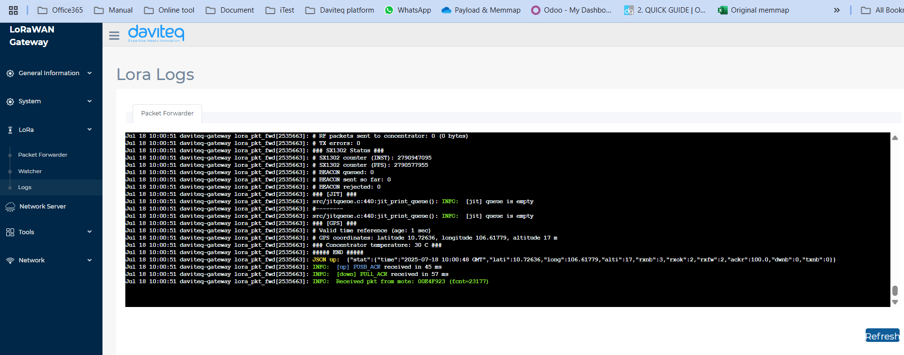
Logs
This is the function of monitoring the loRaWAN network.
2.7 Add the LoraWAN Gateway to Network Server
2.7.1 Add the LoraWAN Gateway to Embedded Chirp Stack Network Server
Please follow instruction at link:
Instruction to configu... | Online Product Manuals & Datasheets
2.7.2 Add the LoraWAN Gateway to External LoRaWAN Network Server
To give an example, please follow the instructions in this link to add LoraWAN gateway to The things Stack network server
2.8 Activate and configure the embedded Node RED development tool
Prerequisite:
The Embedded Chirp Stack Network Server in the PINEX gateway must be active and configured properly to forward data to embedded Node RED development tool. Details to activate and configure embedded Chirp Stack are at the link: https://daviteq.com/en/manuals/books/manual-for-lorawan-sensor/page/instruction-to-configure-embedded-chirpstack-network-server-in-pinex-firmware-6
Please refer the below link for instruction to add the embedded Node RED development tool:
Instructions to config... | Online Product Manuals & Datasheets
No Comments